Table of Contents
Advertisement
Quick Links
Advertisement
Table of Contents

Summary of Contents for RT Systems TM3
- Page 1 TM3 monitoring unit installation and users manual...
-
Page 2: Table Of Contents
TM3 camera view GSM configuration SNMP ethernet/internet configuration (first time) maintenance configuration trouble shooting contact configuration page clean the TM3 monitoring unit alarm profile configuration page dry contact alarm configuration page disposal analogue alarms configuration page specifications transmission selection... -
Page 3: Introduction
The TM3 Unit is capable of logging alarms and analogue sampled data which can be viewed from the web interface. Images from a network enabled camera can be viewed on the web interface. Two onboard relays for controlling external devices and a 12Vdc and 18Vdc power supplies are available on the unit. -
Page 4: Document Overview
The TM3 Unit Installation and Users Manual describes how to install a TM3 Monitoring Unit, how sensors are connected and configuration of the sensor inputs is performed. It also describes maintenance and fault finding. After performing the installation and configuration procedures as set out in this document, the TM3 Unit is ready for installation specific configuration and operational environmental monitoring. -
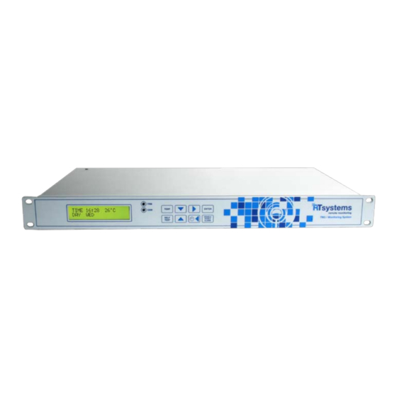
Page 5: Physical Description
physical description front panel item description GSM Transmit Indicator This is a red LED and will light up during GSM transmission and reception. Temperature setup select key TEMP The temperature sensor thresholds and calibration settings are configured when selecting the TEMP key. Press twice in succession to calibrate the sensors. - Page 6 item description Liquid Crystal Display The LCD displays all the system data. GSM Status Indicator Flashing once every second – Initialising, not registered on the GSM network. Flashing once every three seconds – Registered on GSM network. Self test select key SELF TEST By selecting the Self Test key the unit performs a sequence of tests to determine its own health status.
- Page 7 back panel item description GSM ANTENNA SMA connector for GSM antenna connection. CONNECTOR VOLTAGE OUTPUT Provides one 18V dc, 50mA voltage output for sensor supply voltage. 4-20MA INPUTS Three 4-20mA inputs available for connecting third party sensors. TEMPERATURE Four inputs available to connect NTC temperature sensors. SENSOR INPUTS FLOOD SENSOR Two inputs available for multiple flood sensors in series terminated with a 10kΩ...
-
Page 8: Inventory
The supplied cross-over Ethernet cable is used for interface directly to a laptop. installation pack The supplied installation pack consists of 10 cable ties, 4 screws for mounting TM3 unit on 19” rack and 6 cable tie mounts. -
Page 9: Additional Parts
Additional parts are not supplied with the TM3 Unit. These parts are installation specific and are supplied by the installer. NTC temperature sensors Analogue sensor. humidity/temperature sensor (dry contact) Alerts are activated by means of a contact closing/opening when threshold is reached. -
Page 10: Installation
TM3 Unit The TM3 Monitoring Unit is enclosed in a standard 1U 19” enclosure. Install the unit in the front of the rack, which requires one U of rack space. When installing the TM3 Monitoring Unit, take into consideration the following:... -
Page 11: Power Cord, Network Cable And Gsm Antenna Connections
Caution: Make sure you properly ground the appliance by plugging the power cord directly into a wall outlet or by verifying the ground path if using a power strip. Note: The power cord provided is to be used only with the TM3 Monitoring Unit. Note: Only use the GSM antenna provided with the unit. -
Page 12: Sensor Connection
Use the supplied flood sensors on the TM3 Monitoring Unit. Connect the flood sensor at the back of the unit marked “Flood Sensors” to any one of the available two inputs. The flood sensors can be extended using standard CAT-5 cable to a maximum distance of 100 metres. -
Page 13: 4-20Ma Sensors
Sensors” to any one of three available inputs. Extend the 4-20mA sensors using standard CAT-5 cable to a maximum distance as specified by the sensor manufacturer. Tie the cable to the cable support at the back of the unit using the tie wraps provided. The TM3 Monitoring Unit implements a 100Ω... -
Page 14: Initial Configuration
Set the unit’s time and date Connect TM3 to Laptop Configure the GSM settings Configure the Ethernet/network Power up the unit and wait ± 1 minute before starting with initial configuration. An “I” in the right hand corner of the LCD indicates the unit is busy initialising. -
Page 15: Connecting Laptop To Tm3
After the Enter key has been pressed the following display will appear for a couple of seconds. connecting laptop to TM3 Connect crossover cable from TM3 to Laptop Set the local area connection on Laptop – Internet protocol (TCP/IP) Properties –... -
Page 16: Gsm Configuration
The GSM configuration should be done before the Sim Card is installed in the unit. From the Home Page of the TM3 Monitoring Unit select Configuration, now select GSM from the options and the following GSM setup page will be displayed:... - Page 17 The following data can be configured: Cellular Number Enter the cellular number of the Sim card installed in the unit. International number format is required. The correct number is required for the unit’s Self Test function to operate correctly. GSM Service Centre Number (SMSC) Enter the service provider Service Centre Number in this field.
-
Page 18: Ethernet/Internet Configuration (First Time)
ethernet/internet configuration (first time) The unit is shipped with the following default network settings: IP Address 192.168.0.50 Gateway Address 192.168.0.2 Sub-Net Mask 255.255.255.0 DNS IP Address 192.168.0.4 The Ethernet data can be changed and configured on the web interface. Select Configuration on the Home Page icon bar, now select Ethernet/Internet and the Ethernet/Internet Configuration page appears. - Page 19 The data will not be stored in this case. The IP Set utility on the CD can be used to set the TM3’s IP Address. Enter the unit’s Mac Address and the required TM3 IP Address.
-
Page 20: Configuration
configuration This section describes generic configuration procedures which are required to configure a unit for a specific operational installation. Configuring a unit entails the following basic steps by selecting the appropriate TABS on the web interface TAB bar: Set up your contacts in the Contacts Configuration Page. Here you specify all the numbers and Step 1: names to which SMSs have to be sent. -
Page 21: Contact Configuration Page
From the Home Page of the TM3 Monitoring Unit select Contact Configuration Page. The following page will be displayed: The following data can be configured: Cellular Phone Number Enter the cellular number of the contacts to which SMSs are required to be sent. -
Page 22: Alarm Profile Configuration Page
From the Home Page of the TM3 Monitoring Unit select the Alarm Profile Configuration Page. The alarm profiles are configurable on three separate pages ie, Alarm Profile Matrix 1, Alarm Profile Matrix 2 and Alarm Profile Matrix 3. Each has to be configured in order to complete the profiles for all the alarms. -
Page 23: Dry Contact Alarm Configuration Page
From the Home Page of the TM3 Monitoring Unit select the Dry Contact Configuration Page. The following page will be displayed:... - Page 24 The following data can be configured: Name Tag This is the alarm name which uniquely identifies the alarm. HI Description Tag This is the alarm fault condition if Active HI is selected. If Active LOW is selected the normal condition description of the alarm is entered. HI SMS Tick Box Tick this box if an SMS is required when this alarm condition is activated.
-
Page 25: Analogue Alarms Configuration Page
From the Home Page of the TM3 Monitoring Unit select Analogue Alarms Configuration Page and Transmission Selection. The following page will be displayed: The following data can be configured: SMS tick box Select which alarms will be sent by SMS. -
Page 26: Analogue Names
From the Home Page of the TM3 Monitoring Unit select Analogue Alarms Configuration Page and Analogue Names. The following page will be displayed: The following data can be configured: Name Tag This is the alarm name which uniquely identifies the alarm. -
Page 27: Configuration Page
configuration page The following configuration options are available on the Configuration Page: 4-20mA Sensor 1 4-20mA Sensor 2 4-20mA Sensor 3 Ethernet/Internet Self Test Temperature Sensors Disabled Alarms Uncleared Alarms General Camera SNMP... -
Page 28: 4-20Ma Sensor Configuration Page
4-20mA sensor configuration page From the Home Page of the TM3 Monitoring Unit select Configuration Page. Select one of the three 4-20mA Sensor options for configuration. The following page will be displayed. (The configuration procedure for all three sensors is identical.) - Page 29 The following data can be configured: 4mA signal (zero level value) Enter the zero level of the connected sensor, corresponding to its 4mA level, in this field. 20mA signal (full scale level value) Enter the full scale level of the connected sensor, corresponding to its 20mA level, in this field.
-
Page 30: Self Test Configuration Page
From the Home Page of the TM3 Monitoring Unit select Configuration Page and from the option list select Self Test. The following page will be displayed: The following data can be configured: Day of scheduled weekly Self Test Select the day of the week when the scheduled self test will be performed. -
Page 31: Temperature Sensor Configuration Page
From the Home Page of the TM3 Monitoring Unit select Configuration Page and from the option list select Temperature Sensors. The following page will be displayed: The following data can be configured: Non-critical Temperature sensor hysteresis (T1) - Page 32 Note 1: Hysteresis represents the difference between the alarm activation set point (threshold) and the alarm cleared value. For example, temperature sensor 1, non-critical alarm will be triggered at 26° C when the temperature increases, the alarm will be de-activated below 24°...
-
Page 33: Disabled Alarms Configuration Page
From the Home Page of the TM3 Monitoring Unit select Configuration Page and from the option list select Disabled Alarms. The following page will be displayed: The following data can be configured: Time for broadcasting daily Disabled alarms report Enter the time of day when the daily Disabled alarms report will be compiled and sent. -
Page 34: Uncleared Alarms Configuration Page
From the Home Page of the TM3 Monitoring Unit select Configuration Page and from the option list select Uncleared Alarms. The following page will be displayed. The following data can be configured: Time for broadcasting daily... -
Page 35: General Configuration Page
From the Home Page of the TM3 Monitoring Unit select Configuration Page and from the option list select General. The following page will be displayed: The following data can be configured: SITE ID of TM3 Enter a unique identification for the unit. -
Page 36: Camera Configuration Page
From the Home Page of the TM3 Monitoring Unit select Configuration Page and from the option list select Camera. The following page will be displayed: The following data can be configured: IP address of Camera Enter the IP Address of the camera to be accessed. -
Page 37: Snmp Configuration Page
SNMP configuration page From the Home Page of the TM3 Monitoring Unit select Configuration Page and from the option list select SNMP. The following page will be displayed: The following data can be configured: SNMP Manager IP address 1 IP Address to where SNMP traps are sent. -
Page 38: Security Configuration Page
Select Save to store data on the unit after all fields have been configured. Select Cancel and follow the prompted instructions to revert back to the previous settings. The data will not be stored in this case. symbol description Only one log-in connection is allowed on the TM3 Monitoring Unit. After accessing the web interface log out, see next paragraph. -
Page 39: Log Out Page
From the Home Page of the TM3 Monitoring Unit select Log Out. The following page will be displayed: The operator will be prompted to confirm log out when Log Out is selected. -
Page 40: Front Panel Functions
On the front panel of the TM3 Monitoring Unit there are a couple of functions available to either configure the unit or select a particular function. The functions available are the following: TEMP Configure the temperature sensor thresholds and calibration data. -
Page 41: Self Test
self test By selecting the Self Test key, the unit performs a sequence of tests to determine its own health status. While the test is in progress, the following screen will be displayed: Once the self test has been completed, a message will be displayed indicating whether the test has been successful or not. In the event of the test being successful, a “Self Test Pass”... -
Page 42: Disable/Enable All Alarms
disable/enable all alarms By selecting the Disable/Enable All Alarms key, all alarms will be disabled. Indication of this condition is displayed on the LCD as well as on the right top corner of the Home Page. To enable all alarms the Disable/Enable All Alarms key must be pushed again. Alarms will enable after one hour if the Disable/Enable All Alarms key is not selected within the hour. -
Page 43: Gsm Sms Data Access
GSM sms data access The TM3 Monitoring Unit can be configured and interrogated using SMS messages. The SMS commands are listed below. Included on the utility CD is a software utility MonitorProg.exe which can be used for configuration of the unit. Refer to the help function of the software for operator instructions. - Page 44 sms message text description command valid message structure string value Disable all alarms for XX minutes nBg022 nBg022 XX Re-enable all alarms kkp5ef kkp5ef Disable alarm number YY jhgFed jhgFed YY Permanently disable alarm number YY Vaq7b1 Vaq7b1 YY Re-enable alarm number YY Lkp6ef Lkp6ef YY What is the status of alarm number YY? (Active or Not)
- Page 45 sms message text description command valid message structure string value What is the critical temperature threshold for sensor 1? nBg019 nBg019 temperature 2 What is the value of temperature 2? 6kjG25 6kjG25 What is the non-critical temperature threshold for sensor 2? 6kjG28 6kjG28 What is the critical temperature threshold for sensor 2?
-
Page 46: View Data
The TM3 Monitoring Unit displays and collects numerous types of data which can be viewed on the web interface. Data can also be accessed by SNMP and GSM SMS. On the web interface the following data can be viewed: On the Home Page some configuration data is displayed. -
Page 47: Home Page
The Home Page of the TM3 Monitoring Units displays the following information: Site IP address GSM number of the unit Site ID All alarms enable/disable status Individual alarms enabled/disabled status Temperature values of all four temperature sensors 4-20mA values with units... -
Page 48: Alarm Log
alarm log The time, date and alarm description is displayed on the alarm log. Up to 240 log entries are stored. -
Page 49: Graph View
graph view The analogue sensors sampled data are viewable on the web interface. The sensor name, start date and time as well as the sampling period are displayed on the graph. Select the required sensor graph from the drop down list and select Update. By selecting Download, Graph data can be viewed or saved on a PC in Microsoft Office Excel Worksheet Format. -
Page 50: Camera View
camera view Typical camera image of a computer room displayed on the web interface. -
Page 51: Snmp
SNMPv3 has the advantage of authentication above SNMPv1. The following SNMP functionality is available on the TM3 Monitoring Unit. Refer to the TM3 MIB.txt file supplied on the utility disc. The TM3 unit has been tested on the following freeware MIB browsers: iReasoning... -
Page 52: Maintenance
NOTE: only qualified service and installation personnel are allowed to perform maintenance tasks on the TM3 Monitoring Unit. WARNING: high voltage (110V/2240Vac) warning inside the TM3 enclosure. The following items can be replaced as part of required maintenance. -
Page 53: Trouble Shooting
item description Power Inlet Fuse, 2A, 250V, 5x20 Glass Fuse Battery Fuse, 2A, 250V Power Supply 12V, 2.3AH Sealed Lead Acid Battery, PN PS2.3-12 3V Coin Cell Battery, CR2032 SD Card GSM Sim Card trouble shooting problem cause/correction Unit does not Check that SD Card is installed and that default or specific configuration data is on the SD Card. -
Page 54: Clean The Tm3 Monitoring Unit
To clean the TM3 Monitoring Unit, gently wipe surfaces with a clean, dry cloth. disposal symbol description WARNING: The TM3 unit contains replaceable lithium coin cell and lead acid batteries. Please take the batteries into consideration when disposing of the unit. -
Page 55: Specifications
specifications electrical Input voltage, nominal 110–240 VAC; 50/60 Hz Maximum total current draw 0,5 A physical Dimensions (H x W x D) 44,45 x 480 x 282mm (Standard 1U 19” Rack) Weight 4,6 kg environmental Elevation (above MSL) Operating 0 to 3 000 m (0 to 10 000 ft) Storage 0 to 15 000 m (0 to 50 000 ft) Temperature... - Page 56 compliance (pending) Electrical Fast Transients (EFT) IEC 61000-4-4 Electrostatic Discharge (ESD) IEC 61000-4-2 Surges IEC 61000-4-5 Radiated Susceptibility IEC 801-3 Voltage Dips and Interruptions IEC 61000-4-11 Conducted Susceptibility IEC 61000-4-6 Emissions and Harmonics IEC 61000-3-3 and IEC 61000-3-2 General Products Safety Directive 2001/95/EC RoHS Compliance 2002/95/EC...
- Page 57 Notes...
- Page 58 Notes...
- Page 60 RT Systems Johannesburg RT Systems Cape Town physical address postal address physical address 157 Barry Hertzog Ave 34 Wandel Street Postnet Suite 93 Emmarentia Ext 1 Private Bag X7 Gardens 2195 Cape Town Parkview South Africa 8001 2122 cell +27 11 646 5250...
Need help?
Do you have a question about the TM3 and is the answer not in the manual?
Questions and answers