Satel CA-64 EPS - Zone Expander With Power Supply Manual
- Manual (4 pages) ,
- Quick start manual (4 pages)
Advertisement
FEATURES
The CA-64 EPS zone expander can be used in conjunction with CA-64, INTEGRA and VERSA control panels. This manual applies to the expander with electronics version 2.3 and firmware version 4.00 (or newer).
- 8 programmable zones:
- support for NO and NC type detectors, as well as roller shutter motion detectors and vibration detectors;
- support for single EOL and double EOL loops.
- Programmable end-of-line resistors value.
- Additional tamper input, NC type.
- 1.2 A switching-mode power supply.
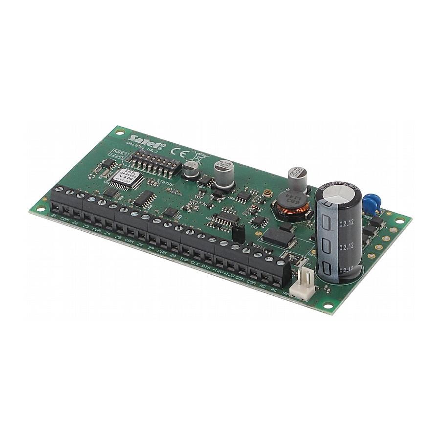
FIGURE 1. View of the expander electronics board.

- a set of DIP-switches (see: DIP-SWITCHES).
- STATUS LED:
- blinking – data exchange with the panel;
- illuminated – no communication with the control panel.
- pins to set up the battery charging current:
- pins shorted – 350 mA
- pins open – 700 mA
- leads to connect the battery (12 V lead-acid sealed battery). If the battery voltage drops below 11 V for longer than 12 minutes (3 battery tests), the expander will indicate battery failure. When the voltage goes down to approx. 9.5 V, the battery will be disconnected.
Description of the terminals:
Z1...Z8 – zones.
COM – common ground.
TMP – t amper loop input (NC) – if no tamper contact is connected to this terminal, it should be shorted to common ground.
CLK – clock.
DTA – data.
+12V – p ower supply output. A device requiring 12 V DC supply can be connected to this output. The sum of the currents consumed by the devices supplied from the expander and the battery charging currents must not exceed the power supply output current.
AC – power supply input (required transformer: 18 V AC, 40 VA).
DIP-SWITCHES
Use the switches 1-5 to set an address. The address must be different from that of the other modules connected to the communication bus of alarm control panel. In case of interaction with the VERSA control panel, an address from the 12 (0Ch) to 14 (0Eh) range must be set. In order to determine the expander address, add up the values set on individual switches as shown in Table.
| DIP-switch number | 1 | 2 | 3 | 4 | 5 |
| Numerical value* | 1 | 2 | 4 | 8 | 16 |
*for switch in ON position
The switches 6 and 7 must be set to OFF position.
Use the switch 8 to define how the expander will be identified by the control panel:
OFF – CA-64 EPS. The expander does not support roller shutter motion detectors and vibration detectors. Programming the end-of-line resistors value is not available.
ON – CA-64 EPSi. The expander supports roller shutter motion detectors and vibration detectors. Programming the end-of-line resistors value is available (make sure that a suitable value is programmed).
 The switch 8 must be in position OFF for the CA-64 control panel and for the INTEGRA panels with firmware up to and including version 1.04. These control panels do not support the CA-64 EPSi expander.
FIGURE 2. Examples of address setting (address 14 (0Eh) is one of the addresses required for interaction with the VERSA series control panels).

FIGURE 3. Connecting power supply.

INSTALLATION AND START-UP
Disconnect power before making any electrical connections. Never connect two devices with a power supply unit to one transformer.
Before connecting the transformer to a 230 V AC circuit, make sure the circuit is de-energized.
Never connect a discharged battery to the expander (when the voltage across battery terminals without a load connected is lower than 11 V).
The expander should be installed indoors, in spaces with normal humidity of air. The connections should be made with the typical unscreened straight-through cable (using the „twisted pair" type of cable is not recommended).
- Fasten the expander board in the enclosure.
- Using the DIP-switches, set the suitable expander address and define how it is to be identified.
- Wire the CLK, DTA and COM terminals to the corresponding terminals of the control panel communication bus (see: installer manual for alarm control panel). The wires must be run in one cable.
- Wire the enclosure tamper contact to the TMP and COM terminals (or short the TMP terminal to the COM terminal).
- Complete the zone wiring (for wiring description refer to the alarm control panel installer manual).
- Connect the transformer primary winding to a 230 V AC circuit. Make sure the selected circuit is protected by a suitable safeguard and remains energized at all times (de-energize the circuit before connecting the transformer).
- Connect the transformer secondary winding to the expander AC terminals.
- Using the jumper, set up the battery charging current (350 mA or 700 mA).
- Connect the battery to the dedicated leads (positive terminal to RED lead, negative terminal to BLACK lead). The expander will not start after connecting the battery alone. The battery provide backup power in the event of an AC power failure.
- Energize the 230 V AC circuit.
- Start the identification function in the control panel. When the identification is completed, the zones will be assigned respective numbers in the alarm system (zone numeration rules are described in the alarm control panel manual).
SPECIFICATIONS

SATEL sp. z o.o.
ul. Schuberta 79; 80-172 Gdansk, POLAND
tel. +48 58 320 94 00; info@satel.pl;
www.satel.eu

Documents / Resources
References
Download manual
Here you can download full pdf version of manual, it may contain additional safety instructions, warranty information, FCC rules, etc.
Download Satel CA-64 EPS - Zone Expander With Power Supply Manual
Advertisement


Need help?
Do you have a question about the CA-64 EPS and is the answer not in the manual?
Questions and answers