Advertisement
Quick Links
The CA-64 DR expander for DALLAS chip readers is a device designed to interact with the
CA-64 and INTEGRA alarm control panels. It supports the DALLAS chip readers which
transfer data in the Touch Memory (DALLAS) standard. The expander can work
simultaneously with two heads of this type. Its function is to control the access to and operate
the electromagnetic door lock (or to control the operation of another device requiring the
access control). This manual is drawn up for the expander with firmware version 1.06 or later.
Note: Using of all available in the module functions is possible only in case of interact with
control panels of INTEGRA.
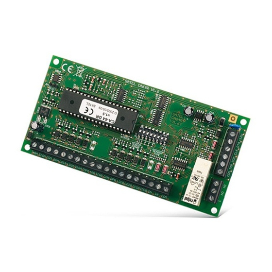
1. Module description
Figure 1. Diagrammatic view of the module electronics board.
Legend:
1 – LED indicator of the process of communication between control panel and expander:
− blinking – data exchange with the panel;
− ON – no data exchange with the panel (the module and the control panel connecting
wire is damaged, identification of module is not carried out or the STARTER program
is started in the control panel).
2 – package of DIP switches designed for setting individual address of the module (see:
DIP
SWITCHES
3 – LED indicator of the relay ON state.
4 – relay. The C, NC and NO of the relay are galvanically isolated from electric circuits of
the module. In normal state the C terminal is shorted to the NC terminal, while the NO
"DALLAS" CHIP READERS
®
).
EXPANDER FOR
CA-64 DR
ca64dr_en 07/08
Advertisement

Related Manuals for Satel CA-64 DR


Summary of Contents for Satel CA-64 DR
- Page 1 ® ca64dr_en 07/08 The CA-64 DR expander for DALLAS chip readers is a device designed to interact with the CA-64 and INTEGRA alarm control panels. It supports the DALLAS chip readers which transfer data in the Touch Memory (DALLAS) standard. The expander can work simultaneously with two heads of this type.
-
Page 2: Dip Switches
SATEL CA-64 DR terminal is isolated. On actuation of the relay, the C terminal becomes shorted to the NO terminal, and the NC terminal becomes cut off (which is signaled by the LED going on). Description of terminals: +12V – power supply input CLK, DTA –... -
Page 3: Mounting And Installation
CA-64 DR SATEL address: Fig. 2. Example of DIP-switch settings. address: Fig. 3. Example of DIP-switch settings. 2. Mounting and installation The expansion modules can be mounted in the CA-64 OBU-EXA metal housing, or in the OPU-1 A plastic ones. - Page 4 SATEL CA-64 DR 2. Call the "Expander identification" function in the LCD keypad ( Service mode Structure Hardware Identification). identification completed, indicating communication with the alarm control panel will start blinking. Note: In the process of identification, the control panel writes to the module memory a special (16-bit) number intended to detect the module presence in the system.
- Page 5 CA-64 DR SATEL 5. Programming the module settings The expander can be programmed by means of LCD keypad ( Service mode Structure Hardware Expanders Settings expander selection) or computer with a suitable program (DLOAD64 or DLOADX). The settings and options available for programming are described below.
- Page 6 SATEL CA-64 DR Lock feature ON if partition armed [On if part. armed] – selecting this option sets the bistable operating mode of the relay (i.e. the status of NO and NC relay contact changes to the opposite one when the partition is armed and returns to the normal state when the partition is disarmed).
- Page 7 CA-64 DR SATEL Arming [Reader A arm./Reader B arm.] – this option defines whether the partition can be armed by using the DALLAS chip. Hold the chip at the reader to arm the partition. INTEGRA Hardware signaling of readout – activation of this option will start the chip code readout signaling which is independent of the control panel.
- Page 8 SATEL CA-64 DR Meanings of the sound signals generated on reading the DALLAS chip code are as follows: • one short beep (accompanied by a single flash of the LED) – acknowledgement of the chip code readout – a hardware function, performed by the expander;...
-
Page 9: Technical Data
CA-64 DR SATEL 7. Technical data Supply voltage ....................10.5V...14V DC Maximum current consumption (without heads) ...............70mA Maximum relay switchable voltage ................AC 250V Maximum relay switchable current..................2A Environmental class......................... II Operating temperature range................-10 °C...+55 °C Dimensions of module electronics board ..............68x140 mm... - Page 10 The latest EC declarations of conformity and certificates are available for downloading on the website www.satel.pl SATEL sp. z o.o. ul. Schuberta 79 80-172 Gdańsk POLAND tel. + 48 58 320 94 00 info@satel.pl www.satel.pl...
Need help?
Do you have a question about the CA-64 DR and is the answer not in the manual?
Questions and answers