Advertisement
INT-IORS • INT-ORS
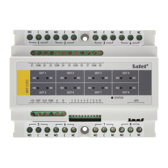
DIN-RAIL EXPANDER
The INT-IORS expander enables the system to be expanded by 8 programmable wired
zones and 8 programmable wired outputs. The INT-ORS expander enables the system to be
expanded by 8 programmable wired outputs. The modules are designed for mounting on 35
mm DIN rail, which facilitates installation process and integration with other automation
systems. The expanders are supported by INTEGRA / INTEGRA Plus / CA-64 alarm control
panels and ACCO-NT access control panel. Additionally, the INT-ORS expander is supported
by the VERSA / PERFECTA alarm control panels. This manual applies to the expanders with
electronics version 2.1 and firmware version 2.04 (or newer).
1. Features
8 programmable hardwired zones
support for NO and NC type detectors, as well as roller shutter and vibration detectors,
support for Single EOL, Double EOL and Triple EOL configuration (Triple EOL when
working with INTEGRA Plus control panels),
programming end-of-line resistor values.
8 programmable relay outputs for control of the electrical devices supplied with 230 V AC.
Capable of being integrated with dedicated power supply unit (operation in "expander with
power supply" mode).
Connectable to RS-485 bus (firmware update through the bus).
35 mm DIN rail mountable.
2. Specifications
Supply voltage ................................................................................................... 12 V DC ±15%
Standby current consumption
Maximum current consumption
Relay output rating (resistive load) .................................................................. 16 A / 230 V AC
+12V output rating ............................................................................................ 2,5 A / 12 V DC
Environmental class according to EN50130-5 ......................................................................... II
Operating temperature range.............................................................................-10 °C...+55 °C
Maximum humidity .......................................................................................................... 93±3%
Dimensions ....................................................................................................122 x 93 x 58 mm
Weight
The declaration of conformity may be consulted at www.satel.eu/ce
only
INT-IORS:
INT-IORS .....................................................35 mA
INT-ORS ......................................................35 mA
INT-IORS ...................................................350 mA
INT-ORS ....................................................310 mA
INT-IORS ...................................................... 300 g
INT-ORS ....................................................... 285 g
int-iors_en 08/19
Advertisement
Table of Contents

Related Manuals for Satel INT-IORS


Summary of Contents for Satel INT-IORS
-
Page 1: Specifications
DIN-RAIL EXPANDER int-iors_en 08/19 The INT-IORS expander enables the system to be expanded by 8 programmable wired zones and 8 programmable wired outputs. The INT-ORS expander enables the system to be expanded by 8 programmable wired outputs. The modules are designed for mounting on 35 mm DIN rail, which facilitates installation process and integration with other automation systems. - Page 2 INT-IORS / INT-ORS SATEL 3. Description Explanations to Fig. 1: LED indicators of the status of individual relays: red LED ON – the relay is inactive, green LED ON – the relay is active. LED indicating the status of communication with the control panel: ON –...
- Page 3 (see: Table 2 for INT-IORS expander and Table 3 for INT-ORS expander). In the case of the INT-IORS expander, if the switch is set in ON position, the expander will be always identified as an expander with power supply (regardless of whether the dedicated power supply is connected to the PCB connector, or not).
- Page 4 The conductors must be run in one cable. 4. In the case of INT-IORS expander, connect the detectors to the zones (for description of detector connection, please refer to the manual of control panel installer).
- Page 5 SATEL INT-IORS / INT-ORS 6. Power up the expander. 7. Depending on the control panel type: alarm control panel: run the device identification function (for more information, refer to the alarm control panel manual),...
- Page 6 (see: ACCO-USB converter manual). You can find a program for updating the expander firmware and a detailed description of the firmware update procedure on the www.satel.eu website. SATEL sp. z o.o. • ul. Budowlanych 66 • 80-298 Gdańsk • POLAND tel. +48 58 320 94 00 www.satel.eu...
Need help?
Do you have a question about the INT-IORS and is the answer not in the manual?
Questions and answers