Advertisement
FEATURES
- 8 programmable hardwired zones:
- support for NO and NC type detectors, as well as roller shutter and vibration detectors;
- support for Single EOL, Double EOL and Triple EOL configuration (Triple EOL when working with INTEGRA Plus control panels);
- programming end-of-line resistor values.
- NC type tamper input.
- Capable of being integrated with dedicated power supply unit (operation in „expander with power supply" mode).
- Connectable to RS-485 bus (firmware update through the bus).
The INT-E expander enables the system to be expanded by 8 programmable wired zones. The expander works with INTEGRA, INTEGRA Plus, VERSA and CA-64 control panels.
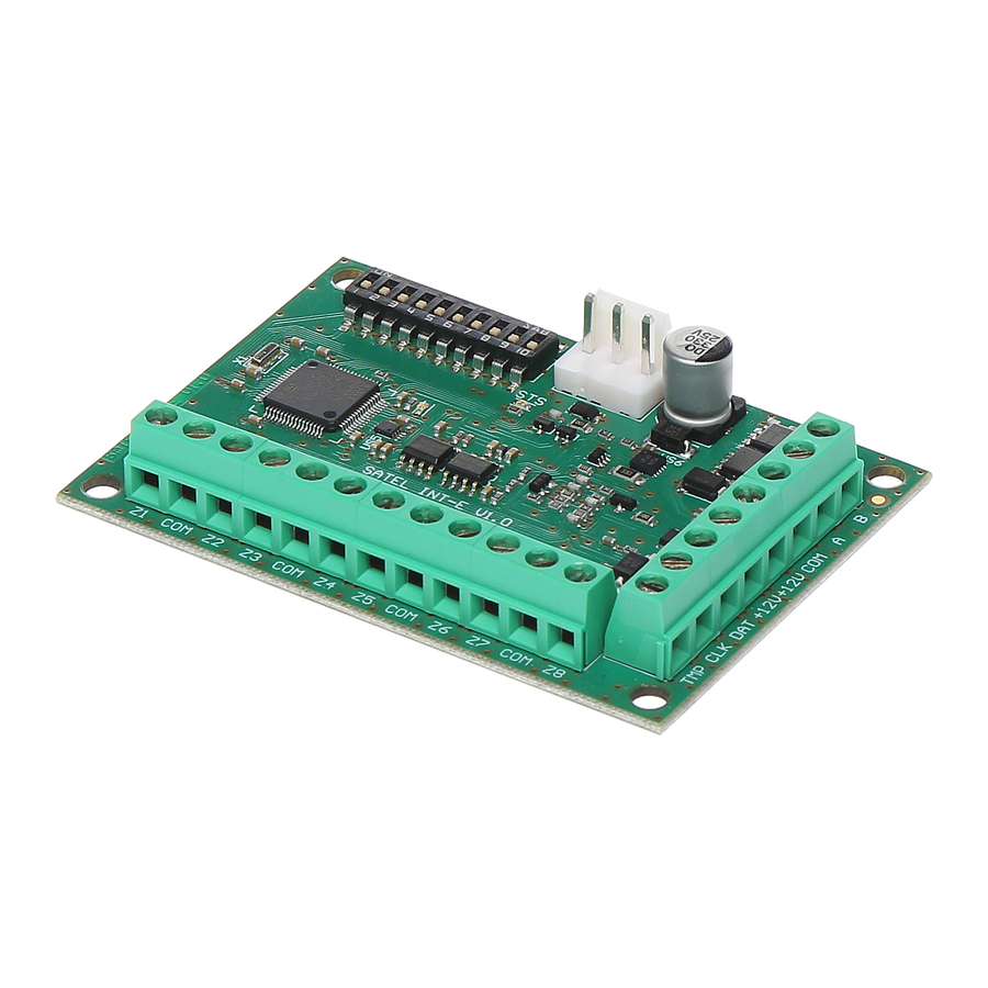
ELECTRONICS BOARD
Figure 1

Explanations to Fig. 1:
- DIP-switches (see: DIP-SWITCHES).
- connector for a dedicated power supply unit (e.g. APS-412). If a power supply is connected to the connector, the expander will be identified as an expander with power supply.
- STS LED indicating the status of power supply connected to the connector:
- ON – power supply is working normally,
- blinking – power supply is reporting a trouble.
- LED indicating the status of communication with the control panel:
- ON – no communication with the control panel,
- blinking – communication with the control panel OK.
Description of terminals:
| Z1...Z8 - | zones. |
| COM - | common ground. |
| TMP - | tamper input (NC) – if not used, it should be shorted to the common ground. |
| CLK - | clock (communication bus). |
| DAT - | data (communication bus). |
| +12V - | +12 V DC power input / output. |
| A, B - | RS-485 bus. |

Do not connect power to the terminals, if the dedicated power supply unit is connected to the connector on electronics board.
DIP-SWITCHES
The DIP-switches 1-5are used for address setting. A numerical value is assigned to each switch. In OFF position, the value is 0. Numerical values assigned to individual switches in ON position are shown in Table 1. The sum of numerical values assigned to switches 1-5 means the address set on the module. The address must be different from that on the other modules connected to the communication bus of the control panel. If the module is used in conjunction with the VERSA control panel, an address from the 12 (0Ch) to 14 (0Eh) range must be set.
TABLE 1.
| DIP-switch number | 1 | 2 | 3 | 4 | 5 |
| Numerical value | 1 | 2 | 4 | 8 | 16 |
The DIP-switch 10 allows you to define how the expander will be identified by the control panel (see: Table 2). If the dedicated power supply unit is connected to the connector on electronics board, the device will be identified as expander with power supply. Functional differences resulting from identification of the expander are presented in Table 3.
TABLE 2.
| Identification of device | |||
| expander w/o power supply | expander with power supply | ||
| DIP-switch position | ON | CA-64 E | CA-64 EPS |
| OFF | INT-E / CA-64 Ei | INT-EPS / CA-64 EPSi | |
TABLE 3.
| INT-E INT-EPS | CA-64 Ei CA-64 EPSi | CA-64 E CA-64 EPS | |
| support for roller shutter / vibration detectors |  | | – |
| support for Triple EOL configuration (INTEGRA Plus) | | – | – |
| programming end-of-line resistor values | | | – |
Notes:
- The expander will be identified as INT-E / INT-EPS by INTEGRA / INTEGRA Plus control panels with firmware version 1.12 or newer.
- The switch 10 must be set in ON position, if the expander is connected to the following control panels:
- CA-64;
- INTEGRA with firmware version from 1.00 to 1.04, inclusive. If the switch is set in OFF position, the control panel will not be able to identify the expander.
Figure 2

Fig. 2. Shows some examples of DIP-switches settings (address 14 (0Eh) is one of the addresses required for operation of the expander with VERSA control panels).
INSTALLATION AND START-UP
Disconnect power before making any electrical connections.
The expander is designed for indoor installation.
- Fasten the expander electronics board in the enclosure.
- Using the DIP-switches, set the suitable expander address and define how it is to be identified.
- Connect the CLK, DAT and COM terminals to the corresponding terminals of the control panel communication bus (see: installer manual for alarm control panel). It is recommended that an unshielded non-twisted cable be used to make the connection. If you use the twisted-pair type of cable, remember that CLK (clock) and DAT (data) signals must not be sent through one pair of twisted conductors. The conductors must be run in one cable.
- If the expander is to supervise the enclosure tamper contact, connect the wires of tamper contact to the TMP and COM terminals. If the expander is not to supervise the enclosure tamper contact, connect the TMP terminal to the expander COM terminal.
- Connect detectors to the expander zones (for description of how the detectors should be connected, please refer to the installer manual of alarm control panel).
- Depending on the selected method of expander powering, connect the dedicated power supply unit to the connector on expander electronics board or connect the power leads to the +12V and COM terminals (the expander may be powered directly from the control panel, from an expander with power supply or from a power supply unit).
The expander must not be powered from both sources at the same time.
- Power on the alarm system.
- Start the identification function in the control panel. After expander identification is completed, the zones will be assigned their respective numbers in the alarm system. The zone numeration rules are described in the control panel manual. The control panel monitors presence of the identified modules. If the module is disconnected from communication bus, position of DIP-switches is changed, or the device is replaced with another one with DIP-switches set in the same way, a tamper alarm will be triggered.
UPDATING THE EXPANDER FIRMWARE
Using the RS-485 bus, connect the expander to the ACCO-USB converter, and then connect the converter to the computer (see: ACCO-USB converter manual). You can find a program for updating the expander firmware and a detailed description of the firmware update procedure on the www.satel.eu website.
SPECIFICATIONS
| Supply voltage | 12 V DC ±15% |
| Standby current consumption | 35 mA |
| Maximum current consumption | 80 mA |
| +12V output rating | 2.5 A / 12 V DC |
| Security grade according to EN50131 – without power supply | Grade 3 |
| Security grade according to EN50131 – with APS-412 power supply | Grade 2 |
| Environmental class according to EN50130-5 | II |
| Operating temperature range | -10°C...+55°C |
| Maximum humidity | 93±3% |
| Dimensions | 80 x 57 mm |
| Weight | 47 g |
The declaration of conformity may be consulted at www.satel.eu/ce

Documents / Resources
References
Download manual
Here you can download full pdf version of manual, it may contain additional safety instructions, warranty information, FCC rules, etc.
Advertisement


Need help?
Do you have a question about the INT-E and is the answer not in the manual?
Questions and answers