Table of Contents
Advertisement
Quick Links
INT-R
UNIVERSAL EXPANDER FOR CARD / IBUTTON READERS
The INT-R expander interfaces with the INTEGRA, INTEGRA Plus and CA-64 alarm control
panels, replacing the previously offered CA-64 SR and CA-64 DR expanders. This manual
applies to the expander with electronics version 2.0 and firmware version 3.00 (or later).
1. Features
Support for two proximity card / DALLAS iButton readers.
Support for WIEGAND 26 interface readers.
Arming / disarming and alarm clearing by using the readers.
Access control features:
single door control,
relay output for control of electric strike, electromagnetic lock or another door actuator,
dedicated input for connecting a door opening sensor,
input for door unlocking with a button,
capability to automatically unlock the door in case of fire alarm.
Control of 24. MONO
Additional NC type tamper input.
Dedicated power supply connector socket.
The dedicated power supply unit can be connected to the expanders
manufactured after 9 September 2014.
2. Specifications
Supply voltage ................................................................................................... 12 V DC ±15%
Standby current consumption ........................................................................................110 mA
Maximum current consumption......................................................................................150 mA
Relay output rating (resistive load) ...................................................................... 5 A / 30 V DC
+12V output rating ............................................................................................ 2.5 A / 12 V DC
Environmental class................................................................................................................. II
Operating temperature range.............................................................................-10 °C...+55 °C
Maximum humidity .......................................................................................................... 93±3%
Dimensions ........................................................................................................... 140 x 68 mm
Weight................................................................................................................................. 80 g
The declaration of conformity may be consulted at www.satel.eu/ce
and 25. BI
SWITCH
SWITCH
type outputs.
int-r_en 09/14
Advertisement
Table of Contents

Subscribe to Our Youtube Channel
Related Manuals for Satel INT-R


Summary of Contents for Satel INT-R
- Page 1 UNIVERSAL EXPANDER FOR CARD / IBUTTON READERS int-r_en 09/14 The INT-R expander interfaces with the INTEGRA, INTEGRA Plus and CA-64 alarm control panels, replacing the previously offered CA-64 SR and CA-64 DR expanders. This manual applies to the expander with electronics version 2.0 and firmware version 3.00 (or later).
-
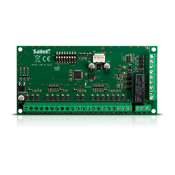
Page 2: Electronics Board
INT-R SATEL 3. Electronics board Fig. 1. View of the electronics board. Explanations for Fig. 1: DIP-switches for setting address (see: „Address setting” p. 4). LED indicating the status of communication with the control panel: ON – no communication with the control panel, blinking –... - Page 3 SATEL INT-R communication bus terminals. +12 V DC inputs / outputs. common ground. RS-485 bus terminals. 4. Expander operating modes The device can operate as: I - CA-64 SR expander, supporting the CZ-EMM readers (CZ-EMM, CZ-EMM2, CZ-EMM3 and CZ-EMM4) manufactured from May 2005 factory default setting;...
-
Page 4: Address Setting
INT-R SATEL 5. Address setting To set address, use the switches 1-5 of the DIP-switch package. A numerical value is assigned to each switch. In OFF position, the value is 0. Numerical values assigned to individual switches in ON position are shown in Table 1. The sum of numerical values assigned to switches 1-5 means the address set on the module. - Page 5 The length of the cable connecting the reader and the expander should not exceed 30 m. Connecting the proximity card readers Connect the proximity card reader manufactured by SATEL to the expander terminals as displayed in Table 2. Expander terminal...
- Page 6 INT-R SATEL Expander terminal Terminal description Color of reader wire Reader A Reader B data (0) white SIG1A SIG1B gray common ground yellow green LED control green LD1A LD1B red LED control brown LD2A LD2B Table 3. The way of connecting wires of DALLAS iButton reader to terminals.
- Page 7 SATEL INT-R the event log of the control panel (the proximity card readers will audibly signal the long opened door). If value 0 is programmed, the door status will not be monitored. Dependent on door 1 [Dependent door1] / Dependent on door 2 [Dependent door2] – you may define the door that must be closed to be able to unlock the door controlled by the partition keypad (to activate the relay).
- Page 8 The reader presence control can be effected if the reader is provided with a presence control circuit (the white wire in proximity card readers manufactured by SATEL). Confirmation: Sound (Reader A) [Reader A sound] / Confirmation: Sound (Reader B) [Reader B sound] –...
- Page 9 SATEL INT-R Auto-Arm delay countdown [Auto-arm delay] – if this option is enabled, the proximity card readers will audibly signal the auto-arming delay countdown in the partition to which the expander belongs. CHIME [Chime zones] – if this option is enabled, the proximity card readers will audibly signal...
-
Page 10: Optical Signaling
If the reader B is used to activate the relay, the "User exit" event will be saved. 8.1 Optical signaling The readers offered by SATEL come with one bicolor LED (emitting red and green light) or two LEDs (red and green). Information on partition and expander status The LEDs indicate status of the partition to which expander belongs, as well as lack of communication between the expander and the control panel. - Page 11 SATEL INT-R A sequence of 7 beeps of diminishing duration, repeated every few seconds – auto- arming delay countdown. 1 short beep every 150 ms – long open door. 2 short beeps every second – entry delay countdown. Continuous beep – alarm.
- Page 12 SATEL sp. z o.o. • ul. Budowlanych 66 • 80-298 Gdańsk • POLAND tel. + 48 58 320 94 00 info@satel.pl www.satel.eu...
Need help?
Do you have a question about the INT-R and is the answer not in the manual?
Questions and answers