Table of Contents
Advertisement
Quick Links
The CA-64 ADR addressable zones expander is a device intended to work with the CA-64
and INTEGRA alarm control panels. It allows extension of the alarm system by up to 48
zones (depending on the control panel type) which have identical features as the main board
zones. The expander module is fitted with a built-in switching-mode power supply of 2.2A
capacity. It also has short-circuit protection of the supply output, and battery charging and
testing circuits with disconnection of discharged battery.
Note: Installation of the CA-64 ADR expander in the CA-64 alarm system will exclude
the option to install other zones expanders as well as the CA-64 PP zone /
output expander.
This manual has been drawn up for the expander with firmware in version 1.5 or later.
1. Description of electronics board
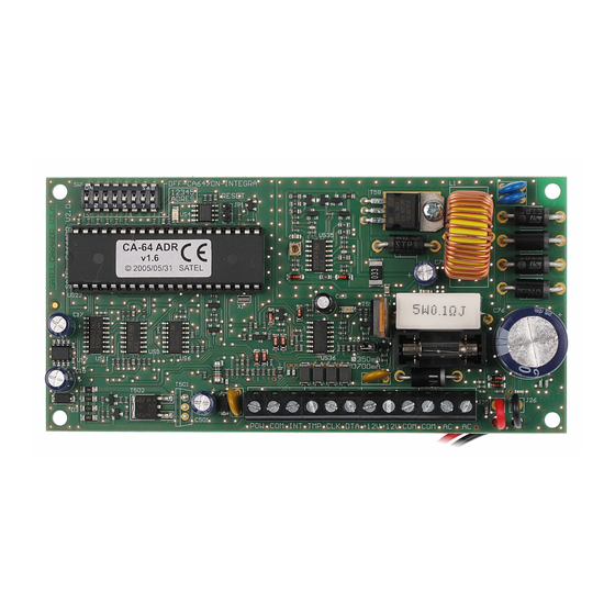
Explanations to Figure 1:
1 – package of DIP-switches designed for setting individual address of the module
(switches 1-5) and for selecting the type of control panel the module interacts with
(switch 8: OFF – CA-64; ON – INTEGRA).
2 – LED indicator of the process of communication with the control panel. In the normal
operating mode of the module, the LED is blinking with variable frequency.
ADDRESSABLE ZONES EXPANDER
®
Fig. 1. Schematic view of the module electronics board.
CA-64 ADR
ca64adr_e 12/05
red
black
Advertisement
Table of Contents

Related Manuals for Satel CA-64 ADR


Summary of Contents for Satel CA-64 ADR
- Page 1 ® ca64adr_e 12/05 The CA-64 ADR addressable zones expander is a device intended to work with the CA-64 and INTEGRA alarm control panels. It allows extension of the alarm system by up to 48 zones (depending on the control panel type) which have identical features as the main board zones.
- Page 2 (leads: INT, COM, POW). The addressable detector is obtained from a typical detector (NO, NC) upon installing inside it the SATEL CA- 64 ADR MOD addressable module (see: CA-64 ADR MOD module instructions). Using digital...
- Page 3 (see Table 2). For each group of 8 addresses of the CA-64 ADR MOD modules, 1 address on the expander bus and 8 zones in the system are reserved. Remember, however, that having even one detector with installed CA- 64 ADR MOD module, in which an address from any group of 8 addresses is set, will take up an address on the expander bus and reserve 8 zones in the system.
- Page 4 Table 2. 4. Numbering the addressable zones The CA-64 ADR MOD module has a package of DIP switches designed for setting individual address of the module. 64 different addresses can be set (from 0 to 63). In order to determine the module address, add up the numbers set on particular DIP switches, according to Table 3.
- Page 5 2 LCD keypads (addresses 0 and 1) are connected to the keypad bus. All the keypad zones are used in the system. CA-64 ADR expander with address 0 is connected to the expander bus. 20 detectors with installed addressable modules are connected to the control panel by means of the expander (the module addresses must be set within the ranges 0 to 15 and 20 to 23).
- Page 6 CA-64 ADR white black blue CA-64 ADR MOD adressable module detector Fig. 6. Example of connecting the addressable detector without tamper control. 6. Installation The addressable zones expander may be installed in any housing designed for control panel (with transformer and place for battery).
- Page 7 If current consumption by the addressable detectors and battery exceeds capacity of the power supply unit, some of the detectors are to be powered from an additional power supply (e.g. the SATEL APS-15 or APS-30 power supply units).
-
Page 8: Technical Data
Hardware Identification). Having identified the CA-64 ADR expander, control panel will automatically identify the CA-64 ADR MOD addressable modules. When the identification is completed, the LED indicator of communication with the control panel will start blinking. After identification, all the new zones are programmed to factory defaults, the detector type being set to zero (no detector).
Need help?
Do you have a question about the CA-64 ADR and is the answer not in the manual?
Questions and answers