Advertisement
The CA-64 EPS zone expander is designed for operation in the intruder alarm systems. It
can work in conjunction with the SATEL made CA-64, INTEGRA and VERSA alarm control
panels. It enables the alarm system to be expanded by additional 8 zones. The expander
zones can be programmed as NO, NC, EOL, 2EOL/NO or 2EOL/NC. The value of resistors
in EOL and 2EOL configurations is programmable. The expander can support vibration and
roller shutter motion detectors. The module has a built-in switching-mode power supply of 1.2
A capacity. It also has battery charging circuit and testing circuit with disconnection of
discharged battery. This manual applies to the expander with electronics version 2.0 and
firmware version 2.0 (or newer).
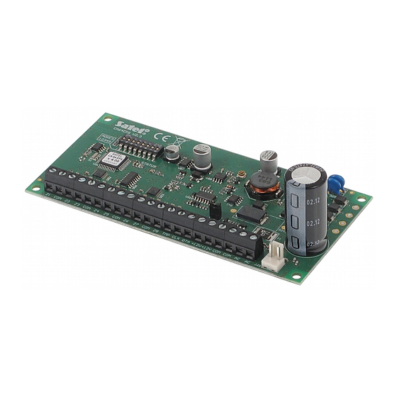
1. Description of electronics board
ADRES
12345
Z1
COM
Z2
Z3 COM Z4
Fig. 1. Schematic view of the expander electronics board.
Explanations to Figure:
1 – a set of DIP-switches for setting individual address of the module and defining how the
expander will be identified and, consequently, what functions will be available (see
DIP-
SWITCHES
2 – LED STATUS to indicate the process of communication between control panel and
expander:
− LED is blinking – data exchange with the panel;
− LED is lit – no communication with the control panel.
3 – pins to set up the battery charging current:
− pins shorted – 350 mA
− pins open – 700 mA
ZONE EXPANDER WITH POWER SUPPLY
®
1
2
STATUS
Z5 COM Z6
Z7 COM Z8 TMP CLK DTA +12V+12V COM COM AC
).
CA-64 EPS
3
350mA
700mA
ca64eps_en 06/09
4
AC
Advertisement
Table of Contents

Related Manuals for Satel CA-64 EPS


Summary of Contents for Satel CA-64 EPS
- Page 1 ® ca64eps_en 06/09 The CA-64 EPS zone expander is designed for operation in the intruder alarm systems. It can work in conjunction with the SATEL made CA-64, INTEGRA and VERSA alarm control panels. It enables the alarm system to be expanded by additional 8 zones. The expander zones can be programmed as NO, NC, EOL, 2EOL/NO or 2EOL/NC.
- Page 2 Position of the switch 8 affects the way of expander identification and availability of some functions: • OFF – the expander will be identified as CA-64 EPS. Support for the roller shutter motion and vibration detectors, as well as programming the resistor value in EOL and 2EOL configurations are not available.
- Page 3 SATEL CA-64 EPS CA-64 EPS CA-64 EPSi 14 (0Eh) 14 (0Eh) 22 (16h) 22 (16h) Fig. 2. Examples of address setting (address 14 (0Eh) is one of the addresses required for interaction with the VERSA series control panels). 2. Installation and start-up Prior to starting the module hookup, switch off power supply of the security system.
- Page 4 Environmental class according to EN50130-5 .................II Operating temperature range................-10 °C…+55 °C Weight..........................131 g The latest EC declaration of conformity and product approval certificates are available for downloading on website www.satel.pl SATEL sp. z o.o. ul. Schuberta 79 80-172 Gdańsk POLAND tel.
Need help?
Do you have a question about the CA-64 EPS and is the answer not in the manual?
Questions and answers