Advertisement
Quick Links
Download this manual
See also:
Manual
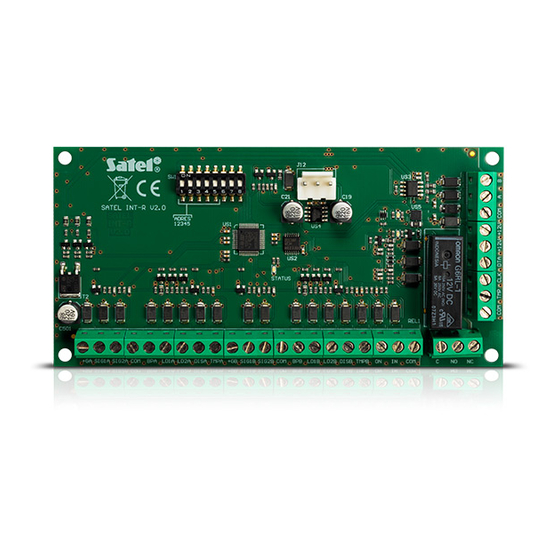
The INT-R expander interfaces with the INTEGRA and CA-64 alarm control panels, replacing
the previously offered CA-64 SR and CA-64 DR expanders. This manual applies to the
expander with electronics version 2.0 and firmware version 3.00 (or later).
1. Features
• Support for two proximity card / DALLAS chip readers.
• Support for WIEGAND 26 interface readers.
• Capability to arm / disarm and clear alarm by using the readers.
• Capability to implement access control function – control of a single door.
• Relay to control the electromagnetic door lock.
• Input for door status control.
• Input for door unlocking with a button.
• Capability to automatically unlock the door in case of fire alarm.
• Additional NC type tamper input.
2. Installation and start-up
Disconnect power before making any electrical connections.
The expander is designed for indoor installation, in spaces with normal air humidity.
1. Secure the expander board in its enclosure.
2. Determine the expander operating mode (see: S
).
MODE
3. With the DIP-switches, set the appropriate expander address. To set an address, use the
switches 1-5. The address must be different from that in the other modules connected to
the expander bus. The address is the sum of numerical values set on the switches 1-5
(see Table 1).
Switch number
Numerical value
Table 1. Numerical values corresponding to the switches set to ON position (in the OFF
4. Connect the CLK, DTA and COM terminals with wires to the appropriate terminals of the
control panel expander bus. To make a connection, it is recommended to use an
unscreened straight-through cable. When using the twisted-pair type of cable, the CLK
(clock) and DTA (data) signals must not be sent through one twisted pair. The wires must
be run in one cable. The cable length should not exceed 1000 m. If it exceeds 300
meters, it may be necessary to use several wires connected in parallel for each signal.
5. Connect readers to the respective terminals (see: C
6. Connect the door status control detector to the IN and COM terminals.
UNIVERSAL EXPANDER
FOR CARD / CHIP READERS
®
position, the value 0 is assigned to each switch)
INT-R
ELECTING THE EXPANDER OPERATING
1
2
3
1
2
4
ONNECTING THE READERS
int-r_en 09/11
4
5
8
16
).
Advertisement

Related Manuals for Satel INT-R


Summary of Contents for Satel INT-R
- Page 1 INT-R int-r_en 09/11 The INT-R expander interfaces with the INTEGRA and CA-64 alarm control panels, replacing the previously offered CA-64 SR and CA-64 DR expanders. This manual applies to the expander with electronics version 2.0 and firmware version 3.00 (or later).
-
Page 2: Electronics Board
INT-R SATEL 7. Connect the electromagnetic door lock to the relay terminals. 8. If the door is to be unlocked by means of a monostable switch, connect the switch button to the ON and COM terminals. 9. Connect the enclosure tamper switch wires to the TMP and COM terminals (or short- circuit the TMP terminal to the COM terminal). - Page 3 SATEL INT-R 6 - terminals to connect the reader A (see: C ONNECTING THE READERS 7 - terminals to connect the reader B (see: C ONNECTING THE READERS 8 - NO type input for relay control (enables the door to be unlocked without using a reader).
- Page 4 The length of the cable connecting the reader and the expander should not exceed 30 m. Connecting the proximity card readers Connect the proximity card reader manufactured by SATEL to the expander terminals as displayed in Table 2. Expander terminal...
- Page 5 SATEL INT-R 3. Programming the expander The expander can be programmed using: − LCD keypad: ERVICE MODE TRUCTURE ARDWARE XPANDERS ETTINGS [module name]; − computer running D X or D 64 program: "Structure" window "Hardware" tab LOAD LOAD "Expansion modules" branch module name.
- Page 6 Lack of the reader will generate a trouble (see also the R EADER TAMPER ALARM option). The reader presence control can be effected if the reader is provided with a presence control circuit (the white wire in proximity card readers manufactured by SATEL).
- Page 7 SATEL INT-R Confirmation: Sound (Reader A) [Reader A sound] / Confirmation: Sound (Reader B) [Reader B sound] – after reading the card code and its verification by the panel, the reader can inform the user by means of sounds whether the requested function will be executed...
- Page 8 INT-R SATEL No auto-reset after 3 tamp. [No autorst.3t.] – it is possible to disable the feature limiting the number of tamper alarms from the expander to three (this feature prevents the same events from being repeatedly recorded and applies to consecutive, non-cleared alarms).
-
Page 9: Optical Signaling
SATEL INT-R 4.1 Optical signaling The readers offered by SATEL come with one bicolor LED (emitting red and green light) or two LEDs (red and green). Information on partition and expander status The LEDs indicate status of the partition to which expander belongs, as well as lack of communication between the expander and the control panel. -
Page 10: Specifications
INT-R SATEL 1 long beep every 3 seconds, followed by a series of short beeps for 10 seconds and 1 long beep – exit delay countdown (if the delay time is shorter than 10 seconds, only the final sequence of short beeps will be generated). - Page 11 The declaration of conformity may be consulted at www.satel.eu/ce SATEL sp. z o.o. ul. Schuberta 79 80-172 Gdańsk POLAND tel. + 48 58 320 94 00 info@satel.pl www.satel.pl...
Need help?
Do you have a question about the INT-R and is the answer not in the manual?
Questions and answers