
Subscribe to Our Youtube Channel
Related Manuals for National Instruments PXI-8101


Summary of Contents for National Instruments PXI-8101
- Page 1 NI PXI-8101/8102 User Manual NI PXI-8101/8102 User Manual June 2010 372800C-01...
- Page 2 Thailand 662 278 6777, Turkey 90 212 279 3031, United Kingdom 44 (0) 1635 523545 For further support information, refer to the Technical Support and Professional Services appendix. To comment on National Instruments documentation, refer to the National Instruments Web site at and enter ni.com/info the Info Code feedback ©...
- Page 3 Warranty The NI PXI-8101 and NI PXI-8102 are warranted against defects in materials and workmanship for a period of one year from the date of shipment, as evidenced by receipts or other documentation. National Instruments will, at its option, repair or replace equipment that proves to be defective during the warranty period.
- Page 4 Operation of this hardware in a residential area is likely to cause harmful interference. Users are required to correct the interference at their own expense or cease operation of the hardware. Changes or modifications not expressly approved by National Instruments could void the user’s right to operate the hardware under the local regulatory rules.
-
Page 5: Table Of Contents
NI PXI-8101/8102 Functional Description........1-2 National Instruments Software ..................1-4 Chapter 2 Installation and Configuration Installing the NI PXI-8101/8102 ...................2-1 How to Remove the Controller from the PXI Chassis ........2-4 BIOS Setup ........................2-5 Accessing BIOS Setup Utility .................2-5 Main Setup Menu ....................2-6 Advanced Setup Menu ..................2-6... - Page 6 Front Panel Features ...................... 3-11 Data Storage ........................3-11 Chapter 4 Common Configuration Questions General Questions ......................4-1 Boot Options........................4-1 Cables and Connections ....................4-2 Software Driver Installation ..................4-3 Upgrade Information ..................... 4-4 PXI Configuration ......................4-6 NI PXI-8101/8102 User Manual ni.com...
- Page 7 Contents Chapter 5 Troubleshooting Appendix A Specifications Appendix B Technical Support and Professional Services Glossary Index © National Instruments Corporation NI PXI-8101/8102 User Manual...
-
Page 8: About This Manual
This manual contains detailed instructions for installing and configuring your National Instruments PXI-8101/8102 embedded controller kit. How to Use the Documentation Set Begin by reading the NI PXI-8101/8102 Installation Guide, a brief quick-start guide that describes how to install and get started with your controller. -
Page 9: Related Documentation
PXI Software Specification, Revision 2.1, PXI Systems Alliance • Serialized IRQ Support for PCI Systems Specification, Revision 6.0, Compaq Computer et al. • Universal Serial Bus (USB) Specification, Revision 2.0 • Digital Visual Interface (DVI) Specification, Revision 1.0 NI PXI-8101/8102 User Manual ni.com... -
Page 10: Introduction
Additionally, PXI meets the more specific needs of instrumentation users by adding an integrated trigger bus and reference clock for multiple-board synchronization, a star trigger bus for very precise timing, and local buses for side-band communication between adjacent peripherals. © National Instruments Corporation NI PXI-8101/8102 User Manual... -
Page 11: Ni Pxi-8101/8102
Celeron 575 processor (2.00 GHz single core processor) with all the standard I/O and a 80 GB (or larger) hard drive. The NI PXI-8101 RT (Flash HD) version of the NI PXI-8101 ® has a 4 GB (or larger) Flash hard drive. The NI PXI-8102 has an Intel Celeron Dual-Core T3100 processor (1.9 GHz) with all the standard I/O... - Page 12 Super I/O Watchdog COM 1 Timer Figure 1-1. NI PXI-8101/8102 Block Diagram The NI PXI-8101/8102 consists of the following logic blocks on the CPU module and the I/O module. The CPU module has the following logic blocks: ® ® •...
-
Page 13: National Instruments Software
PXI/CompactPCI backplane. • The Super I/O block represents the other peripherals supplied by the NI PXI-8101/8102. The NI PXI-8101/8102 has one serial port, and an ECP/EPP parallel port. • The Gigabit Ethernet connects to either 10 Mbit, 100 Mbit, or 1,000 Mbit Ethernet interfaces. - Page 14 RTSI or PXI synchronization, self-calibration, messaging, and acquiring data to extended memory. For more information visit ni.com/daq National Instruments’ Modular Instruments use specialized drivers suited to each product’s specialization. Express VIs provide customized, interactive programming of instruments in a single interface and soft front panels provide an interface for testing the functionality of each instrument with no programming required.
- Page 15 Chapter 1 Introduction NI-VISA is the National Instruments implementation of the VISA specification. VISA is a uniform API for communicating and controlling USB, Serial, PXI, VXI, and various other types of instruments. This API aids in the creation of portable applications and instrument drivers. For...
-
Page 16: Installation And Configuration
NI PXI-8101/8102 controller. Installing the NI PXI-8101/8102 This section contains general installation instructions for the NI PXI-8101/8102. Consult your PXI chassis user manual for specific instructions and warnings. Plug in your chassis before installing the NI PXI-8101/8102. The power cord grounds the chassis and protects it from electrical damage while you install the module. - Page 17 1 Protective Screw Cap (4X) Figure 2-1. Removing Protective Screw Caps Make sure the injector/ejector handle is in its downward position. Align the NI PXI-8101/8102 with the card guides on the top and bottom of the system controller slot. Caution Do not raise the injector/ejector handle as you insert the NI PXI-8101/8102.
- Page 18 Raise the injector/ejector handle until the module firmly seats into the backplane receptacle connectors. The front panel of the NI PXI-8101/8102 should be even with the front panel of the chassis. Tighten the four bracket-retaining screws on the top and bottom of the front panel to secure the NI PXI-8101/8102 to the chassis.
-
Page 19: How To Remove The Controller From The Pxi Chassis
Chapter 2 Installation and Configuration Figure 2-2 shows an NI PXI-8101 installed in the system controller slot of a National Instruments PXI-1036 chassis. You can place PXI devices in any other slots. An NI PXI-8102 would appear the same installed in the chassis. -
Page 20: Bios Setup
Chapter 2 Installation and Configuration BIOS Setup You can change the NI PXI-8101/8102 configuration settings in the BIOS setup program. The BIOS is the low-level interface between the hardware and operating system software that configures and tests your hardware when you boot the system. The BIOS setup program includes menus for configuring settings and enabling NI PXI-8101/8102 controller features. -
Page 21: Main Setup Menu
The Main setup menu reports the following configuration information: • BIOS Version and Build Date—These values indicate the version of the PXI-8101/8102 controller BIOS and the date on which the BIOS was built. • Processor Type, Speed, and Number of Cores—These values indicate the type of processor used in the PXI-8101/8102 controller, the speed of the processor, and the number of processor cores. -
Page 22: Sata Configuration Submenu
• Core Multi-Processing Controller—This setting specifies whether or not the second core of the processor is enabled or disabled. The default value is Enabled. © National Instruments Corporation NI PXI-8101/8102 User Manual... -
Page 23: Video Configuration Submenu
DOS. The default value is Enabled. Note Certain real-time applications may require you to disable this setting to reduce loop time jitter. When the controller is configured to boot LabVIEW RT, legacy USB support is automatically disabled. NI PXI-8101/8102 User Manual ni.com... -
Page 24: Serial/Parallel Port Configuration Submenu
Parallel Port—This setting enables or disables the onboard parallel port. The default value is Enabled. • Device Settings—This item displays the current base address and interrupt request level (IRQ) information for the onboard parallel port. © National Instruments Corporation NI PXI-8101/8102 User Manual... -
Page 25: Trigger Router Configuration Submenu
By default, the target will automatically attempt to connect to the network using Note DHCP. If the target is unable to initiate a DHCP connection, the target connects to the network with a link-local IP address or 169.254.x.x NI PXI-8101/8102 User Manual 2-10 ni.com... -
Page 26: Boot Setup Menu
Only one device of a given type will be shown in this list. If more than one device Note of the same type exists, use the Device BBS Priorities submenus to re-order the priority of devices of the same type. © National Instruments Corporation 2-11 NI PXI-8101/8102 User Manual... -
Page 27: Boot Settings Configuration Submenu
The highest priority device is displayed on the main Boot Option Priorities list. Optionally, each device can also be Disabled if the device should never be used as a boot device. NI PXI-8101/8102 User Manual 2-12 ni.com... -
Page 28: Cd/Dvd Rom Drive Bbs Priorities Submenu
User's password is set, then this is a power on password and must be entered to boot or enter the BIOS setup program. In the BIOS setup program, the User will have Administrator rights. By default, no password is specified. © National Instruments Corporation 2-13 NI PXI-8101/8102 User Manual... -
Page 29: Save & Exit Menu
If BIOS setup options have been changed and saved, a reboot will be required and the boot override selection will not be valid. NI PXI-8101/8102 User Manual 2-14 ni.com... -
Page 30: System Cmos
Chapter 2 Installation and Configuration System CMOS The NI PXI-8101/8102 contains a backed-up memory used to store BIOS configuration information. Complete the following steps to clear the CMOS contents: Power off the chassis. Remove the controller from the chassis. Press and hold down push-button switch SW2 for 2 to 3 seconds. -
Page 31: Labview Rt Installation
The label also can be removed and placed on the front of the controller for easier access. Click on the appropriate PXI controller entry to access the Network Settings tab in the right pane view. NI PXI-8101/8102 User Manual 2-16 ni.com... - Page 32 You may also reboot the controller by right-clicking on the target name under Remote Systems and selecting Reboot. After rebooting the PXI controller it will appear in the Remote Systems category with the assigned name. © National Instruments Corporation 2-17 NI PXI-8101/8102 User Manual...
- Page 33 Chapter 2 Installation and Configuration Figure 2-4 shows the RT Series PXI target, PXI-8101, configured to automatically obtain an IP address from a DHCP server, as indicated in the IP Settings section of the figure. The NI PXI-8102 would appear similar in MAX.
-
Page 34: Labview Rt Configuration Switches
Note You must reboot the controller for any changes to take place. The NI PXI-8101/8102 controller includes the following LabVIEW RT configuration switches: • Switch 1—Boot LabVIEW RT: Set this switch to ON to boot LabVIEW RT. -
Page 35: Drivers And Software
The directory structure under the directory is logically organized images into several levels. In the directory, you will find a directory, images manuals directory, and a directory. drivers NI PXI-8101/8102 User Manual 2-20 ni.com... -
Page 36: Pxi Features
PXI Features PXI Trigger Connectivity The SMB connector on the NI PXI-8101/8102 front panel can connect to or from any PXI backplane trigger line. A trigger allocation process is needed to prevent two resources from connecting to the same trigger line, resulting in the trigger being double-driven and possibly damaging the hardware. -
Page 37: Basic Pxi System Configuration
Identify As submenu. Further expanding the PXI System branch shows all devices in the system that can be recognized by NI-VISA. When your controller and all your chassis are identified, file is generated. pxisys.ini NI PXI-8101/8102 User Manual 2-22 ni.com... -
Page 38: Upgrading Ram
PXI specification at www.pxisa.org Upgrading RAM You can change the amount of installed RAM on the NI PXI-8101/8102 by upgrading the SO-DIMM. National Instruments offers the following types of SO-DIMMs for use with the NI PXI-8101/8102 controller. -
Page 39: Hard Drive Recovery
The NI PXI-8101/8102 controller also ships with an OS Recovery DVD that allows you to reinstall your operating system onto your hard drive through an external USB DVD-ROM. -
Page 40: I/O Information
I/O Information Front Panel Connectors Table 3-1 lists various I/O interfaces and their corresponding NI PXI-8101/8102 external connectors, bus interfaces, and functions. Table 3-1. NI PXI-8101/8102 I/O Overview I/O Interface External Connector Description Video DVI-I (24-pin DSUB) Intel Extreme Graphics controller... -
Page 41: Front Panel
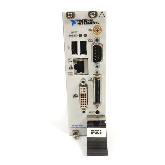
I/O Information Front Panel Figure 3-1 shows the front panel layout and dimensions of the NI PXI-8101. The NI PXIe-8102 has the same front panel layout and dimensions. Dimensions are in inches [millimeters]. 4.393 in. (111.58 mm) 3.748 in. (95.2 mm) 3.551 in. -
Page 42: Dvi-I
Chapter 3 I/O Information DVI-I Figure 3-2 shows the location and pinouts for the DVI-I connector on the NI PXI-8101/8102. Table 3-2 lists and describes the DVI-I connector signals. 1 9 17 NI PXI-8101 Embedded Controller Figure 3-2. DVI-I Connector Location and Pinout Table 3-2. - Page 43 Ground (for +5 V) Hot Plug Detect TMDS Data0– TMDSData0+ TMDS Data0/5 Shield Reserved Reserved TMDS Clock Shield TMDS Clock+ TMDS Clock– Analog Red Analog Green Analog Blue Analog Horizontal Sync Analog GND Return: (analog R, G, B) NI PXI-8101/8102 User Manual ni.com...
-
Page 44: Com1
Chapter 3 I/O Information COM1 Figure 3-3 shows the location and pinouts for the COM1 connector on the NI PXI-8101/8102. Table 3-3 lists and describes the COM1 connector signal. COM1 NI PXI-8101 Embedded Controller Figure 3-3. COM1 Connector Location and Pinout Table 3-3. -
Page 45: Ethernet
Chapter 3 I/O Information Ethernet Figure 3-4 shows the location and pinouts for the Ethernet connector on the NI PXI-8101/8102. Table 3-4 lists and describes the Ethernet connector signals. Ethernet NI PXI-8101 Embedded Controller Figure 3-4. Ethernet Connector Location and Pinout Table 3-4. -
Page 46: Parallel Port
1000 Mbit/sec data rate is selected. Parallel Port Figure 3-5 shows the location and pinouts for the IEEE 1284 (parallel) connector on the NI PXI-8101/8102. Table 3-6 lists and describes the IEEE 1284 connector signals. Parallel port adapter cables are available from National Instruments, part number 777169-01. - Page 47 Data Bit 2 Data Bit 3 Data Bit 4 Data Bit 5 Data Bit 6 Data Bit 7 INIT# Initialize Printer STROBE# Strobe SLCTIN# Select Input AUTOFD# Auto Line Feed +5 V 19–35 Ground Not Connected NI PXI-8101/8102 User Manual ni.com...
-
Page 48: Universal Serial Bus
Chapter 3 I/O Information Universal Serial Bus Figure 3-6 shows the location and pinouts for the Universal Serial Bus (USB) connectors on the NI PXI-8101/8102. Table 3-7 lists and describes the USB connector signals. NI PXI-8101 Embedded Controller Figure 3-6. USB Connector Location and Pinout Table 3-7. -
Page 49: Trigger
The TRIG connector is the software-controlled trigger connection for routing PXI triggers to or from the backplane trigger bus. Figure 3-8 shows the TRIG connector location on the NI PXI-8101/8102. Table 3-8 lists and describes the trigger connector signals. NI PXI-8101 Embedded Controller Figure 3-8. -
Page 50: Front Panel Features
TRIG Trigger 2 (Shield) Ground Front Panel Features The NI PXI-8101/8102 controller has the following front-panel features: • A controller reset pushbutton (press the button to generate a reset to the controller) • Two front panel LEDs that show PC status –... -
Page 51: Common Configuration Questions
This chapter answers common configuration questions you may have when using the NI PXI-8101/8102 embedded controller. General Questions What do the LEDs on the NI PXI-8101/8102 front panel mean? Refer to the LED status descriptions in the Front Panel Features... -
Page 52: Cables And Connections
There are some limitations when booting from a USB device. Windows XP can be installed from a USB CD-ROM, but earlier versions of Windows cannot. The NI PXI-8101/8102 BIOS configures the USB devices so that they will work in a DOS environment. -
Page 53: Software Driver Installation
How do I connect a standard 25-pin LPT cable to the NI PXI-8101/8102? The NI PXI-8101/8102 uses a type C LPT connector. Most parallel port devices use a type A connector. To use a device with a standard type A LPT connector, you need to use a type C-to-type-A LPT adapter. -
Page 54: Upgrade Information
Chapter 4 Common Configuration Questions How do I install software from a CD? The compact size of the NI PXI-8101/8102 does not allow for an integrated CD-ROM drive. You have the following options: • USB CD-ROM—You can install from a USB CD-ROM using a bootable installation CD. - Page 55 Figure 4-2. Installing a DDR2 SO-DIMM in an NI PXI-8101/8102 Controller How do I upgrade the system hard drive? To upgrade the hard drive, remove the NI PXI-8101/8102 from the PXI chassis. National Instruments offers the following types of hard drives for use with the NI PXI-8101/8102 controller.
-
Page 56: Pxi Configuration
Chapter 4 Common Configuration Questions My NI PXI-8101/8102 does not have an internal floppy drive. Is there a way to use an external drive? Yes. The NI PXI-8101/8102 controller supports and can boot from USB floppy drives. A USB floppy drive will not work with Windows NT4, but will work with Windows 2000 or Windows XP. - Page 57 This chapter answers common troubleshooting questions you may have when using the NI PXI-8101/8102 embedded computer. What if the NI PXI-8101/8102 does not boot? Several problems can cause a controller not to boot. Here are some things to look for and possible solutions.
- Page 58 Enter the BIOS setup program as described in the Accessing BIOS Setup Utility section of Chapter 2, Installation and Configuration. Press <F9> to load BIOS defaults. Answer Y (Yes) to the verification prompt. Select Save and Exit Setup. NI PXI-8101/8102 User Manual ni.com...
- Page 59 Press and hold down push-button switch SW2 for 2 to 3 seconds. The switch location is shown in Figure 5-1. Reinstall the controller in the chassis. Push-Button Switch SW2 Figure 5-1. Clearing the CMOS Contents © National Instruments Corporation NI PXI-8101/8102 User Manual...
- Page 60 Specifications This appendix lists the electrical, mechanical, and environmental specifications of the NI PXI-8101/8102 embedded computer. Features NI PXI-8101/8102 ® ® CPU—NI PXI-8101 Intel Celeron Processor 575 (2.00 GHz single core processor), 667 MHz FSB ® ® CPU—NI PXI-8102 Intel Dual-Core Celeron T3100 (1.9 GHz dual core...
- Page 61 4.0 cm × 13.0 cm × 21.6 cm (1.59 in. × 5.14 in. × 8.51 in.) Slot requirements ........One system slot plus one controller expansion slot Compatibility ..........Fully compatible with PXI specification Weight ............0.645 kg (1.42 lb) typical NI PXI-8101/8102 User Manual ni.com...
- Page 62 Relative humidity ........5% to 95%, noncondensing (Tested in accordance with IEC-60068-2-56.) For chassis that are not available in the online catalog at ni.com, contact National Instruments for supported operating temperatures. 5 to 40 °C for the PXI-1000B DC. Processor should not throttle CPU frequency under reasonable, worst case processor work loads in high operating temperatures.
- Page 63 • IEC 61010-1, EN 61010-1 • UL 61010-1, CSA 61010-1 Note For UL and other safety certifications, refer to the product label or the Online Product Certification section. NI PXI-8101/8102 User Manual ni.com...
- Page 64 For additional environmental information, refer to the NI and the Environment Web page at . This page contains the ni.com/environment environmental regulations and directives with which NI complies, as well as other environmental information not included in this document. © National Instruments Corporation NI PXI-8101/8102 User Manual...
- Page 65 Instruments service representative. For more information about compliance with the EU Battery Directives 2006/66/EC about Batteries and Accumulators and Waste Batteries and Accumulators, visit ni.com/environment/batterydirective National Instruments (RoHS) National Instruments RoHS ni.com/environment/rohs_china (For information about China RoHS compliance, go to ni.com/environment/rohs_china NI PXI-8101/8102 User Manual ni.com...
- Page 66 Technical Support and Professional Services Visit the following sections of the award-winning National Instruments Web site at for technical support and professional services: ni.com • Support—Technical support at includes the ni.com/support following resources: – Self-Help Technical Resources—For answers and solutions,...
- Page 67 You also can visit the Worldwide Offices section of to access the branch ni.com/niglobal office Web sites, which provide up-to-date contact information, support phone numbers, email addresses, and current events. NI PXI-8101/8102 User Manual ni.com...
- Page 68 Glossary Symbol Prefix Value nano –9 μ micro – 6 –3 milli kilo mega giga tera Symbols ° Degrees. Ω Ohms. Percent. Amperes. Alternating Current. ASIC Application-specific integrated circuit. © National Instruments Corporation NI PXI-8101/8102 User Manual...
- Page 69 Direct Current. DDR2 Double Data Rate, second generation. DIMM Dual In-line Memory Module. Direct Memory Access—A method by which data is transferred between devices and internal memory without intervention of the central processing unit. NI PXI-8101/8102 User Manual ni.com...
- Page 70 Federal Communications Commission. 1. Grams. 2. A measure of acceleration equal to 9.8 m/s A measure of random vibration—The root mean square of acceleration levels in a random vibration test profile. Hertz—Cycles per second. © National Instruments Corporation NI PXI-8101/8102 User Manual...
- Page 71 Light-emitting diode. Meters. master A functional part of a PXI device that initiates data transfers on the PXI backplane. A transfer can be either a read or a write. NI PXI-8101/8102 User Manual ni.com...
- Page 72 Mean time between failure. MTTR Mean time to repair. NI-DAQ The National Instruments software for data acquisition instruments. NI-VISA The National Instruments implementation of the VISA standard—An interface-independent software that provides a unified programming interface for VXI, GPIB, and serial instruments.
- Page 73 Static RAM—A memory chip that requires power to hold its content. It does not require refresh circuitry as a dynamic RAM chip, but it does take up more space and uses more power. Universal Serial Bus. NI PXI-8101/8102 User Manual ni.com...
- Page 74 Glossary Volts. Video Graphics Array—The minimum video display standard for all PCs. Watts. © National Instruments Corporation NI PXI-8101/8102 User Manual...
- Page 75 Serial/Parallel Port Configuration menu configuration, common questions Parallel Port menu, 2-9 boot options, 4-1 Serial Port 0 menu, 2-9 cables and connections, 4-2 Trigger Router Configuration chassis configuration, 2-21 menu, 2-10 figure, 2-22 © National Instruments Corporation NI PXI-8101/8102 User Manual...
- Page 76 2-20 features, 3-11 documentation functional description of NI PXI-8101/8102, conventions used in manual, ix functional overview of NI PXI-8101/8102, 1-2 how to use this documentation set, ix NI resources, B-1 related documentation, x DRIVE LED, 3-11 Gigabit Ethernet, 1-4...
- Page 77 See also configuration modular instruments, 1-5 injector/ejector handle position mouse, plugging PS/2 mouse and keyboard (caution), 2-2 into controller, 4-2 NI PXI-8101 installed in a PXI chassis multichassis configuration in MAX (figure), 2-4 (figure), 2-22 procedure, 2-1 removing NI PXI-8101/8102 from PXI...
- Page 78 2-23, 4-4 specifications, A-1 upgrading, 2-23, 4-4 troubleshooting, 5-1 recycling hardware, A-6 upgrading RAM, 2-23, 4-4 recycling the battery, A-6 NI PXI-8101/8102BIOS setup, 2-5 related documentation, x NI-DAQmx, 1-5 NI-VISA, 1-6 safety specifications, A-4 SATA operating environment specifications, A-3 block, 1-4...
- Page 79 4-3 technical support, B-1 using with PS/2 mouse and keyboard, 2-3 training and certification (NI resources), B-1 trigger, 3-10, 4-6 connector location and pinout (figure), 3-10 signals (table), 3-11 © National Instruments Corporation NI PXI-8101/8102 User Manual...
Need help?
Do you have a question about the PXI-8101 and is the answer not in the manual?
Questions and answers