
Related Manuals for National Instruments PXI-1000


Summary of Contents for National Instruments PXI-1000
- Page 1 (217) 352-9330 | Click HERE Find the National Instruments PXI-1000/1000B at our website:...
- Page 2 ™ -1000 User Manual PXI-1000 User Manual January 1998 Edition Part Number 321710B-01...
- Page 3 Singapore 2265886, Spain 91 640 0085, Sweden 08 730 49 70, Switzerland 056 200 51 51, Taiwan 02 377 1200, United Kingdom 01635 523545 National Instruments Corporate Headquarters 6504 Bridge Point Parkway Austin, Texas 78730-5039 USA Tel: 512 794 0100 © Copyright 1997, 1998 National Instruments Corporation. All rights reserved.
- Page 4 Important Information Warranty The PXI-1000 is warranted against defects in materials and workmanship for a period of one year from the date of shipment, as evidenced by receipts or other documentation. National Instruments will, at its option, repair or replace equipment that proves to be defective during the warranty period.
- Page 5 This device complies with the FCC rules only if used with shielded interface cables of suitable quality and construction. National Instruments used such cables to test this device and provides them for sale to the user. The use of inferior or nonshielded interface cables could void the user’s authority to operate the equipment under the...
- Page 6 • Mainframe Grounding—The PXI-1000 mainframe requires a connection from the premise wire safety ground to the PXI-1000 chassis ground. The earth safety ground must be connected during use of this equipment to minimize shock hazards. Refer to the...
-
Page 7: Table Of Contents
Chapter 1 Getting Started Unpacking ........................1-1 What You Need to Get Started ..................1-1 Optional Equipment .......................1-2 Key Features ........................1-2 PXI-1000 Backplane Overview ..................1-3 Interoperability with CompactPCI ..............1-3 System Controller Slot ..................1-5 Star Trigger Slot ....................1-5 Peripheral Slots....................1-5 Local Bus......................1-6 Trigger Bus......................1-6 System Reference Clock..................1-7... - Page 8 Appendix C Customer Communication Glossary Index Figures Figure 1-1. Front View of the PXI-1000 Mainframe ..........1-4 Figure 1-2. Rear View of the PXI-1000 Mainframe..........1-5 Figure 1-3. PXI Local Bus and Star Trigger Routing..........1-6 Figure 2-1. PXI-1000 Mainframe Airflow Side View..........2-2 Figure 2-2.
- Page 9 Table B-4. P2 (J2) Connector Pinout for the Star Trigger Slot .......B-5 Table B-5. P1 (J1) Connector Pinout for the Peripheral Slot ........B-6 Table B-6. P2 (J2) Connector Pinout for the Peripheral Slot ........B-7 © National Instruments Corporation PXI-1000 User Manual...
-
Page 10: About This Manual
Appendix B, Pinouts, describes the P1 and P2 connector pinouts for the PXI-1000 backplane. • Appendix C, Customer Communication, contains forms you can use to request help from National Instruments or to comment on our products and manuals. • Glossary lists abbreviations, acronyms, metric prefixes, mnemonics, symbols, and terms. -
Page 11: Related Documentation
Equipment Practice Customer Communication National Instruments wants to receive your comments on our products and manuals. We are interested in the applications you develop with our products, and we want to help if you have problems with them. To make it easy for you to contact us, this manual contains comment and configuration forms for you to complete. -
Page 12: Getting Started
Getting Started This chapter describes the key features of the PXI-1000, lists the contents of your kit, and lists optional equipment you can order from National Instruments. Unpacking Carefully inspect the shipping container and the mainframe for damage. Check for visible damage to the metal work. Check to make sure all handles, hardware, and switches are undamaged. -
Page 13: Optional Equipment
National Instruments. Optional Equipment An optional rack-mount kit is available from National Instruments. You can use this kit to install the PXI-1000 mainframe into a standard 19 in. (482 mm) instrument cabinet. Contact National Instruments to order the PXI-1000 rack-mount kit. -
Page 14: Pxi-1000 Backplane Overview
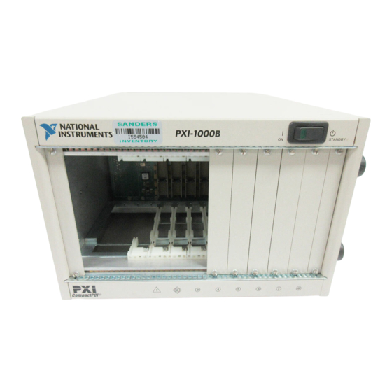
CompactPCI 64-bit specification will function in the PXI-1000. Figures 1-1 and 1-2 show some of the key features and components of the PXI-1000 mainframe. Figure 1-1 shows the front view of the PXI-1000 and Figure 1-2 shows the rear view. -
Page 15: Figure 1-1. Front View Of The Pxi-1000 Mainframe
6 Star Trigger Slot 2 Backplane Connectors 4 Removable Feet 7 System Controller Slot (Located in Slots 1-8) 5 Peripheral Slots 8 Controller Expansion Slots Figure 1-1. Front View of the PXI-1000 Mainframe PXI-1000 User Manual © National Instruments Corporation... -
Page 16: System Controller Slot
4 Circuit Breaker 6 Remote Power Status and Inhibit Connector Figure 1-2. Rear View of the PXI-1000 Mainframe System Controller Slot The System Controller slot is located in Slot 1 of the chassis as defined by the PXI specification. It has three controller expansion slots, which are used for system controller modules that are wider than one slot. -
Page 17: Local Bus
For example, you can use triggers to synchronize the operation of several different PXI peripheral modules. In other applications, one module can control carefully timed sequences of PXI-1000 User Manual © National Instruments Corporation... -
Page 18: System Reference Clock
System Reference Clock The PXI-1000 supplies the PXI 10 MHz system clock signal (PXI_CLK10) independently to each peripheral slot. An independent buffer (having a source impedance matched to the backplane and a skew of less than 1 ns between slots) drives the clock signal to each peripheral slot. -
Page 19: Installation And Configuration
Figure 2-1. Place your PXI-1000 on a bench top or in an instrument rack so that the fans (air inlets) and the air outlet apertures along both sides of the mainframe have adequate ventilation. -
Page 20: Rack Mounting
National Instruments. Refer to the instructions supplied with the rack-mount kit to install your PXI-1000 in an instrument rack. You may wish to remove the feet from your PXI-1000 when rack mounting. To do Note so, remove the two screws holding the feet in place. -
Page 21: Connecting Safety Ground
Connecting to AC Mains Power and Testing Power up Caution Make sure the main power switch located on the rear panel of the PXI-1000 is in the Off position (0). Refer to Figure 1-2, Rear View of the PXI-1000 Mainframe, for a diagram of the main power switch. -
Page 22: Power Supply Voltages At Power Monitoring Connector (Db-9)
Doing so could damage the power supply. You can use a digital voltmeter to ensure all voltage levels in your PXI-1000 are within the allowable limits. Referring to Table 2-1, connect one lead of the voltmeter to a supply pin on the remote power monitoring connector (9-pin D-sub) located on the rear panel. -
Page 23: Remote Power Monitoring And Inhibiting Interface
Chapter 2 Installation and Configuration Remote Power Monitoring and Inhibiting Interface The PXI-1000 mainframe supports remote power monitoring and inhibiting via a 9-pin D-sub connector located on the rear panel. Table 2-2 shows the pinout of the DB-9 connector. Table 2-2. DB-9 Connector Pinout... -
Page 24: Installing Pxi Modules
Secure the module’s front panel to the mainframe using the module’s front-panel mounting screws. PXI-1000 Chassis PXI-8156 System Controller PXI Board Injector/Ejector Rail Injector/Ejector Handle Figure 2-2. Installing PXI or CompactPCI Modules PXI-1000 User Manual © National Instruments Corporation... -
Page 25: Installing Filler Panels
ASCII text. The system integrator can read the .ini file, and configuration utilities and device drivers can also use this .ini file. The PXI-1000 chassis initialization file, , is included on chassis.ini the diskette for your PXI-1000. -
Page 26: Maintenance
Maintenance This chapter describes basic maintenance procedures you can perform on the PXI-1000 mainframe. Service Interval Clean the mainframe fan filters at a maximum interval of six months. Depending upon the amount of use and ambient dust levels in the operating environment, the filters may require more frequent cleaning. -
Page 27: Interior Cleaning
Clean the fan filters by washing them in a mild soap solution and then vacuuming or blowing air through them. Rinse the filters with water and allow them to dry before reinstalling them on the mainframe. PXI-1000 User Manual © National Instruments Corporation... -
Page 28: Resetting The Ac Mains Circuit Breaker
Chapter 3 Maintenance Resetting the AC Mains Circuit Breaker If your PXI-1000 encounters an over-current condition, the circuit breaker located on the rear panel will trip to prevent damage to the mainframe. Complete the following steps to reset the circuit breaker: Turn the front panel (remote) power switch to the Standby position. -
Page 29: Troubleshooting The Pxi-1000
Chapter 3 Maintenance Troubleshooting the PXI-1000 Refer to Table 3-1 to troubleshoot the PXI-1000 mainframe. The table lists possible causes for power failure and recommends ways to correct the problem. Table 3-1. Troubleshooting Possible Cause What to Do PXI-1000 mainframe is not Make sure that the PXI-1000 is connected connected to power source. -
Page 30: Appendix A Specifications
Specifications This appendix contains complete specifications for the PXI-1000 mainframe. Electrical Table A-1. AC Input Specifications Characteristic Description Input Voltage Range 90–264 VAC Input Frequency Range 47 to 63 Hz Over-Current Protection 10 A circuit breaker Operating Current Line Regulation ±... - Page 31 3.3 V clamps at 20% to 30% above output voltage 5 V, +12 V, and –12 V clamps at 10% to 20% above output voltage Power Supply Unit MTBF 90,000+ hr Power Supply/Fan Unit Replacement in under 5 minutes MTTR PXI-1000 User Manual © National Instruments Corporation...
- Page 32 Power Supply/Fan Unit Replacement in under 5 minutes Safety Table A-4. Safety Specifications Characteristic Description Safety Characteristics UL 3111-1, IEC 1010-1, CSA 22.2 No. 1010.1 Installation Category II Pollution Degree 2 Safety Class 1 © National Instruments Corporation PXI-1000 User Manual...
- Page 33 2 km (1.24 mi) * Random vibration profiles were developed in accordance with MIL-T-28800E CLASS 3 and MIL-STD-810E Method 514 Test levels exceed those recommended in MIL-STD-810E for Category 1 (Basic Transportation), Figures 514.4-1 through 514.4-3. PXI-1000 User Manual © National Instruments Corporation...
- Page 34 Accepts both PXI and CompactPCI (PICMG 2.0 R2.1) 3U modules. Backplane Bare-Board UL 94 V-0 recognized Material (File No. E 116551) Backplane Connectors Conform to IEC 917 and IEC 1076-4-101, and are UL 94 V-0 rated © National Instruments Corporation PXI-1000 User Manual...
- Page 35 8.6 kg (19 lb.) Maximum Module Weight 1.8 kg (4 lb.) Materials Sheet Aluminum (5052-H32) and Cold Rolled Steel Finish Unpainted Aluminum Conductive Clear Iridite Cold Rolled Steel Clear Chromate Zinc Plating Paint Polyurethane Enamel PXI-1000 User Manual © National Instruments Corporation...
-
Page 36: Figure A-1. Pxi-1000 Dimensions
Appendix A Specifications Figure A-1 shows the PXI-1000 dimensions. The holes shown are for the installation of the optional rack-mount kit. You can install this kit on the front or rear of the chassis, depending on which end of the chassis you wish to face toward the front of the instrument cabinet. -
Page 37: Appendix B Pinouts
Pinouts This appendix describes the P1 and P2 connector pinouts for the PXI-1000 backplane. Table B-1 shows the P1 (J1) connector pinout for the System Controller slot. Table B-2 shows the P2 (J2) connector pinout for the System Controller slot. - Page 38 3.3V AD[20] AD[19] C/BE[3]# IDSEL AD[23] AD[22] AD[26] V(I/O) AD[25] AD[24] AD[30] AD[29] AD[28] AD[27] REQ# 3.3V AD[31] BRSVP1A5 BRSVP1B5 RST# GNT# BRSVP1A4 V(I/O) INTP INTS INTA# INTB# INTC# INTD# –12V TRST# +12V PXI-1000 User Manual © National Instruments Corporation...
- Page 39 AD[56] AD[55] AD[54] AD[53] AD[59] V(I/O) AD[58] AD[57] AD[63] AD[62] AD[61] AD[60] C/BE[5]# V(I/O) C/BE[4]# PAR64 V(I/O) PXI_BRSVB4 C/BE[7]# C/BE[6]# CLK4 GNT3# REQ4# GNT4# CLK2 CLK3 SYSEN# GNT2# REQ3# CLK1 REQ1# GNT1# REQ2# © National Instruments Corporation PXI-1000 User Manual...
- Page 40 3.3V AD[20] AD[19] C/BE[3]# IDSEL AD[23] AD[22] AD[26] V(I/O) AD[25] AD[24] AD[30] AD[29] AD[28] AD[27] REQ# 3.3V AD[31] BRSVP1A5 BRSVP1B5 RST# GNT# BRSVP1A4 V(I/O) INTP INTS INTA# INTB# INTC# INTD# –12V TRST# +12V PXI-1000 User Manual © National Instruments Corporation...
- Page 41 AD[56] AD[55] AD[54] AD[53] AD[59] V(I/O) AD[58] AD[57] AD[63] AD[62] AD[61] AD[60] C/BE[5]# V(I/O) C/BE[4]# PAR64 V(I/O) PXI_BRSVB4 C/BE[7]# C/BE[6]# PXI_LBR7 PXI_LBR8 PXI_LBR9 PXI_LBR10 PXI_LBR11 PXI_LBR12 SYSEN# PXI_STAR7 PXI_STAR8 PXI_STAR9 PXI_STAR10 PXI_STAR11 PXI_STAR12 © National Instruments Corporation PXI-1000 User Manual...
- Page 42 3.3V AD[20] AD[19] C/BE[3]# IDSEL AD[23] AD[22] AD[26] V(I/O) AD[25] AD[24] AD[30] AD[29] AD[28] AD[27] REQ# 3.3V AD[31] BRSVP1A5 BRSVP1B5 RST# GNT# BRSVP1A4 V(I/O) INTP INTS INTA# INTB# INTC# INTD# –12V TRST# +12V PXI-1000 User Manual © National Instruments Corporation...
- Page 43 AD[56] AD[55] AD[54] AD[53] AD[59] V(I/O) AD[58] AD[57] AD[63] AD[62] AD[61] AD[60] C/BE[5]# V(I/O) C/BE[4]# PAR64 V(I/O) PXI_BRSVB4 C/BE[7]# C/BE[6]# PXI_LBR7 PXI_LBR8 PXI_LBR9 PXI_LBR10 PXI_LBR11 PXI_LBR12 SYSEN# PXI_LBL7 PXI_LBL8 PXI_LBL9 PXI_LBL10 PXI_LBL11 PXI_LBL12 © National Instruments Corporation PXI-1000 User Manual...
-
Page 44: Appendix C Customer Communication
Electronic Services Bulletin Board Support National Instruments has BBS and FTP sites dedicated for 24-hour support with a collection of files and documents to answer most common customer questions. From these sites, you can also download the latest instrument drivers, updates, and example programs. For recorded instructions on how to use the bulletin board and FTP services and for BBS automated information, call 512 795 6990. - Page 45 Telephone and Fax Support National Instruments has branch offices all over the world. Use the list below to find the technical support number for your country. If there is no National Instruments office in your country, contact the source from which you purchased your software to obtain support.
- Page 46 National Instruments for technical support helps our applications engineers answer your questions more efficiently. If you are using any National Instruments hardware or software products related to this problem, include the configuration forms from their user manuals. Include additional pages if necessary.
- Page 47 Complete a new copy of this form each time you revise your software or hardware configuration, and use this form as a reference for your current configuration. Completing this form accurately before contacting National Instruments for technical support helps our applications engineers answer your questions more efficiently.
- Page 48 Other Products List and describe all devices installed in your mainframe. Slot Manufacturer, Description, and Function...
- Page 49 Documentation Comment Form National Instruments encourages you to comment on the documentation supplied with our products. This information helps us provide quality products to meet your needs. Title: ™ -1000 User Manual Edition Date: January 1998 Part Number: 321710B-01 Please comment on the completeness, clarity, and organization of the manual.
-
Page 50: Glossary
Equal or less than. Percent. Amperes. Alternating current. ANSI American National Standards Institute. American Wire Gauge. backplane An assembly, typically a printed circuit board, with connectors and signal paths that bus the connector pins. © National Instruments Corporation PXI-1000 User Manual... - Page 51 1) grams 2) A measure of acceleration equal to 9.8 m/s GPIB General Purpose Interface Bus (IEEE 488). A measure of random vibration. The root mean square of acceleration levels in a random vibration test profile. PXI-1000 User Manual © National Instruments Corporation...
- Page 52 Institute of Electrical and Electronics Engineers. Mainframe peak current. Inches. Pounds. Meters. MTBF Mean time between failure. MTTR Mean time to repair. NEMA National Electrical Manufacturers Association. PCI eXtensions for Instrumentation. Relative humidity. © National Instruments Corporation PXI-1000 User Manual...
- Page 53 Installing such a device into any other slot can damage the device, the VXIbus backplane, or both. Underwriter’s Laboratories. Volts. Peak to peak voltage. Volts alternating current. Watts. PXI-1000 User Manual © National Instruments Corporation...
-
Page 54: Index
(figure), 1-5 connector pinouts. See pinouts. fax and telephone support, C-2 cooling Fax-on-Demand support, C-2 air cooling of PXI-1000, 2-1 to 2-2 filler panel installation, 2-7 air intake (figure), 2-2 FTP support, C-1 filler panel installation, 2-7... - Page 55 1-6 P2 (J2) connector peripheral slot (table), B-7 Star Trigger slot (table), B-5 System Controller slot (table), B-3 maintenance of PXI-1000, 3-1 to 3-4 power cables (table), 1-1 to 1-2 cleaning power monitoring connector. See DB-9 exterior cleaning, 3-2 connector.
- Page 56 1-1 to 1-2 P2 (J2) connector pinouts (table), B-3 specifications (See specifications) system reference clock, 1-7 unpacking, 1-1 PXI-1000 backplane, 1-3 to 1-7 interoperability with CompactPCI, 1-3 local bus, 1-6 technical support, C-1 to C-2 peripheral slots, 1-5 telephone and fax support, C-2...
Need help?
Do you have a question about the PXI-1000 and is the answer not in the manual?
Questions and answers