
Related Manuals for National Instruments PXI-8187


Summary of Contents for National Instruments PXI-8187
- Page 1 NI PXI-8186/8187 User Manual NI PXI-8186/8187 User Manual February 2005 370747C-01...
- Page 2 For further support information, refer to the Technical Support and Professional Services appendix. To comment on National Instruments documentation, refer to the National Instruments Web site at ni.com/info and enter the info code feedback. © 2003–2005 National Instruments Corporation. All rights reserved.
- Page 3 The reader should consult National Instruments if errors are suspected. In no event shall National Instruments be liable for any damages arising out of or related to this document or the information contained in it.
- Page 4 These classes are known as Class A (for use in industrial-commercial locations only) or Class B (for use in residential or commercial locations). All National Instruments (NI) products are FCC Class A products. Depending on where it is operated, this Class A product could be subject to restrictions in the FCC rules. (In Canada, the Department of Communications (DOC), of Industry Canada, regulates wireless interference in much the same way.) Digital...
-
Page 5: Table Of Contents
Introduction Benefits of PXI ......................1-1 NI PXI-8186/8187 ......................1-2 Description ......................1-2 Functional Overview ..................1-2 National Instruments Software ..................1-4 Chapter 2 Installation and Configuration Installing the NI PXI-8186/8187 ...................2-1 How to Remove the Controller from the PXI Chassis ........2-4 BIOS Setup ........................2-4 Entering BIOS Setup ..................2-4... - Page 6 Contents Chapter 3 I/O Information Front Panel Connectors ....................3-1 Front Panel........................3-2 VGA ........................ 3-3 COM1 and COM2................... 3-4 Ethernet ......................3-5 Parallel Port..................... 3-6 Universal Serial Bus..................3-8 PS/2 ......................... 3-9 Trigger......................3-10 GPIB (IEEE 488.2) ..................3-11 Front Panel Features ......................
-
Page 7: About This Manual
About This Manual This manual contains detailed instructions for installing and configuring your National Instruments NI PXI-8186/8187 embedded computer kit. How to Use the Documentation Set Begin by reading the NI PXI-8186/8187 Installation Guide, a brief quick-start guide that describes how to install and get started with your controller. -
Page 8: Related Documentation
About This Manual Text in this font denotes text or characters that you should enter from the monospace keyboard, sections of code, programming examples, and syntax examples. This font is also used for the proper names of disk drives, paths, directories, programs, subprograms, subroutines, device names, functions, operations, variables, filenames, and extensions. -
Page 9: Introduction
Additionally, PXI meets the more specific needs of instrumentation users by adding an integrated trigger bus and reference clock for multiple-board synchronization, a star trigger bus for very precise timing, and local buses for side-band communication between adjacent peripherals. © National Instruments Corporation NI PXI-8186/8187 User Manual... -
Page 10: Ni Pxi-8186/8187
The NI PXI-8186 has a 2.2 GHz processor, all the standard I/O, and a 30 GB (or larger) hard drive. The NI PXI-8187 has a 2.5 GHz processor, all the standard I/O, and a 30 GB (or larger) hard drive. - Page 11 PCI Bus Controller Connectors Triggers 10/100BaseT Ethernet Flash LPC Bus SMB to PXI Trigger LPT 1 Super I/O Watchdog COM 1 COM 2 PS/2 Keyboard/ Mouse Figure 1-1. NI PXI-8186/8187 Block Diagram © National Instruments Corporation NI PXI-8186/8187 User Manual...
-
Page 12: National Instruments Software
• The GPIB block contains the GPIB interface. National Instruments Software National Instruments has developed several software kits you can use with the NI PXI-8186/8187. NI-DAQ has an extensive library of functions that you can call from your application programming environment. These functions include routines... - Page 13 For information on writing your own PXI instrument driver with NI-VISA, refer to the NI-VISA Getting Started manual and the file in readme.txt directory. NI-VISA You also can use the National Instruments LabVIEW, Measurement Studio, ™ ™ and LabWindows /CVI application programs and instrument drivers to ease your programming task.
-
Page 14: Installation And Configuration
Touch the metal part of the case to discharge any static electricity that might be on your clothes or body. Remove the protective plastic covers from the four bracket-retaining screws as shown in Figure 2-1. © National Instruments Corporation NI PXI-8186/8187 User Manual... - Page 15 Chapter 2 Installation and Configuration 1 Protective Screw Cap (4X) Figure 2-1. Removing Protective Screw Caps Make sure the injector/ejector handle is in its downward position. Align the NI PXI-8186/8187 with the card guides on the top and bottom of the system controller slot. Do not raise the injector/ejector handle as you insert the NI PXI-8186/8187.
- Page 16 What if the NI PXI-8186/8187 does not boot? section of Chapter 5, Troubleshooting. Figure 2-2 shows an NI PXI-8186 installed in the system controller slot of a National Instruments PXI-1042 chassis. You can place PXI devices in any other slot. 1 PXI-1042 Chassis 2 NI PXI-8186 Controller 3 Injector/Ejector Rail Figure 2-2.
-
Page 17: How To Remove The Controller From The Pxi Chassis
Chapter 2 Installation and Configuration How to Remove the Controller from the PXI Chassis The NI PXI-8186/8187 controller is designed for easy handling. To remove the unit from the PXI chassis, complete the following steps: Power off the chassis. Remove the bracket-retaining screws in the front panel. Press the injector/ejector handle down. -
Page 18: Main Setup Menu
However, if an IDE/ATA device is not autodetected properly, you can specify it manually by pressing <Enter> on an item. • System Information—This setting displays a screen containing important system information about the NI PXI-8186/8187 controller. © National Instruments Corporation NI PXI-8186/8187 User Manual... -
Page 19: Advanced Setup Menu
Chapter 2 Installation and Configuration DMI Event Logging Submenu Major errors that occur during the BIOS booting process are stored in battery-backed memory on the controller, and remain there until you view and clear them using this submenu. This logging capability allows a system administrator to detect the historical occurrence of faults on a controller. - Page 20 Enabled and modify the base address, IRQ level, and ISA Direct Memory Access (DMA) channel of the port. The default is Auto, which places LPT1 at 0x378, IRQ 7, using ISA DMA Channel 3 if necessary. © National Instruments Corporation NI PXI-8186/8187 User Manual...
- Page 21 Chapter 2 Installation and Configuration • Parallel Port Mode—The PC industry has created several different modes of operation for this port over the years. Usually, the default setting works for all applications. However, if a parallel port device specifically requires a nondefault setting, you can change it here. The default is Bidirectional, for full IEEE 1284 capabilities.
-
Page 22: Pxi Setup Menu
The Exit setup menu includes all available options for exiting, saving, and loading the BIOS default configuration. As an alternative to this screen, press <F9> to load BIOS default settings and <F10> to save changes and exit setup. © National Instruments Corporation NI PXI-8186/8187 User Manual... -
Page 23: System Cmos
Chapter 2 Installation and Configuration The Exit setup menu includes the following settings: • Exit Saving Changes—Any changes made to BIOS settings are stored in the battery-backed System CMOS. The setup program then exits and reboots the controller. • Exit Discarding Changes—Any changes made to BIOS settings during this session of the BIOS setup program are discarded. -
Page 24: Labview Rt Configuration Switches
Switch 1—Boot LabVIEW RT: Set this switch to ON to boot LabVIEW RT. • Switch 2—Boot Safe Mode: Set this switch to ON to boot LabVIEW RT into safe mode to reconfigure TCP/IP settings and © National Instruments Corporation 2-11 NI PXI-8186/8187 User Manual... - Page 25 Chapter 2 Installation and Configuration to download or update software from a host computer. This switch overrides the behavior of Switch 1. Booting the controller into safe mode does not start the embedded LabVIEW RT engine. After changing the settings or software, reboot the controller with this switch OFF to resume normal operation.
-
Page 26: Drivers And Software
National Instruments software manuals, all in Adobe Acrobat format. To access any manual, change your directory to and list the contents of that directory. -
Page 27: Pxi Features
• 1 GB, 128 MB × 64, CL 2.5, 1.15 in. max • National Instruments has tested and verified that the DDR SO-DIMMs we sell work Note with the NI PXI-8186/8187. We recommend you purchase your DDR SO-DIMM modules from National Instruments. Other off-the-shelf DDR SO-DIMM modules are not guaranteed to work properly. -
Page 28: Hard Drive Recovery
If you need to recover your factory-installed operating system from a CD, you can use the included OS re-installation CD with an external CD-ROM drive such as a USB CD-ROM drive. Boot the PXI controller using the © National Instruments Corporation 2-15 NI PXI-8186/8187 User Manual... -
Page 29: Installing An Os
Chapter 2 Installation and Configuration OS re-installation CD to recover the OS. You also may need to reinstall other software after using the CD to recover the OS. Note Recovering the OS using Firstware or the re-installation CD erases the contents of your hard disk. -
Page 30: Front Panel Connectors
PS/2-style keyboard and mouse (mouse requires PS/2 Y splitter) PXI trigger Trigger (SMB) Routing PXI triggers to or from the backplane trigger bus GPIB device GPIB (25-pin Micro D) General-Purpose Interface Bus, IEEE 488.2 © National Instruments Corporation NI PXI-8186/8187 User Manual... -
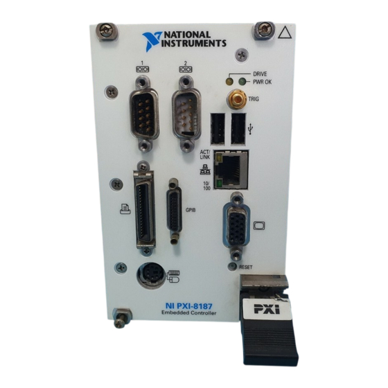
Page 31: Front Panel
Chapter 3 I/O Information Front Panel Figure 3-1 shows the front panel layout and dimensions of the NI PXI-8186/8187. Dimensions are in inches [millimeters]. 3.93 [99.8] 3.69 [93.7] 3.46 [87.9] 2.79 [70.9] 2.10 [53.3] 1.83 [46.5] 0.89 [22.6] NI PXI-8186 Embedded Controller 0.00 [0] Figure 3-1. -
Page 32: Vga
11 6 15 10 5 NI PXI-8186 Embedded Controller Figure 3-2. VGA Connector Location and Pinout Table 3-2. VGA Connector Signals Signal Name Signal Description Green Blue Not Connected Ground Ground Ground Ground © National Instruments Corporation NI PXI-8186/8187 User Manual... -
Page 33: Com1 And Com2
Chapter 3 I/O Information Table 3-2. VGA Connector Signals (Continued) Signal Name Signal Description Ground Not Connected Serial Data HSync Horizontal Sync VSync Vertical Sync Serial Clock COM1 and COM2 Figure 3-3 shows the location and pinouts for the COM1 and COM2 connectors on the NI PXI-8186/8187. -
Page 34: Ethernet
Figure 3-4 shows the location and pinouts for the Ethernet connector on the NI PXI-8186/8187. Table 3-4 lists and describes the Ethernet connector signals. AMP manufactures a mating connector, part number 554739-1. Ethernet NI PXI-8186 Embedded Controller Figure 3-4. Ethernet Connector Location and Pinout © National Instruments Corporation NI PXI-8186/8187 User Manual... -
Page 35: Parallel Port
Figure 3-5 shows the location and pinouts for the IEEE 1284 (parallel) connector on the NI PXI-8186/8187. Table 3-5 lists and describes the IEEE 1284 connector signals. Parallel port adapter cables are available from National Instruments, part number 777169-01. Parallel Port... - Page 36 Data Bit 3 Data Bit 4 Data Bit 5 Data Bit 6 Data Bit 7 INIT* Initialize Printer STROBE* Strobe SLCTIN* Select Input AUTOFD* Auto Line Feed +5 V 19–35 Ground Not Connected © National Instruments Corporation NI PXI-8186/8187 User Manual...
-
Page 37: Universal Serial Bus
Chapter 3 I/O Information Universal Serial Bus Figure 3-6 shows the location and pinouts for the Universal Serial Bus (USB) connector on the NI PXI-8186/8187. Table 3-6 lists and describes the USB connector signals. AMP manufactures a USB mating connector, part number 787633. NI PXI-8186 Embedded Controller Figure 3-6. - Page 38 Table 3-7. PS/2 Connector Signals Y-Splitter Y-Splitter Signal Name Signal Description Keyboard Mouse DATA Data Keyboard Data Keyboard Data Mouse Data Mouse Ground +5 V Clock Keyboard Clock Keyboard Clock Mouse Clock Mouse © National Instruments Corporation NI PXI-8186/8187 User Manual...
-
Page 39: Trigger
Chapter 3 I/O Information Trigger The TRG connector is the software-controlled trigger connection for routing PXI triggers to or from the backplane trigger bus. Figure 3-8 shows the TRG connector location on the NI PXI-8186/8187. Table 3-8 lists and describes the trigger connector signals. NI PXI-8186 Embedded Controller Figure 3-8. -
Page 40: Gpib (Ieee 488.2)
DIO2* Data Bit 2 DIO3* Data Bit 3 DIO4* Data Bit 4 EOI* End or Identify DAV* Data Valid NRFD* Not Ready for Data NDAC* Not Data Accepted IFC* Interface Clear © National Instruments Corporation 3-11 NI PXI-8186/8187 User Manual... -
Page 41: Front Panel Features
Chapter 3 I/O Information Table 3-9. GPIB Connector Signals (Continued) Signal Name Signal Description SRQ* Service Request ATN* Attention SHIELD Chassis ground DIO5* Data Bit 5 DIO6* Data Bit 6 DIO7* Data Bit 7 DIO8* Data Bit 8 REN* Remote Enable 18–25 Logic Ground Front Panel Features... -
Page 42: Common Configuration Questions
The internal IDE hard drive • An external SCSI hard drive or CD-ROM if an SCSI adapter, such as the PXI-8214, is used • A network PXE server on the same subnet © National Instruments Corporation NI PXI-8186/8187 User Manual... -
Page 43: Cables And Connections
Chapter 4 Common Configuration Questions • An external USB mass storage device such as a USB hard drive or CD-ROM • An external USB floppy drive There are some limitations when booting from a USB device. Windows XP Note can be installed from a USB CD-ROM, but earlier versions of Windows cannot. The NI PXI-8186/8187 BIOS configures the USB devices so that they will work in a DOS environment. -
Page 44: Software Driver Installation
GPIB driver in the Device Manager. If you need more assistance, refer ni.com/support/install Note Click the Scan for Hardware Changes in the Device Manager button to force redetection of the GPIB hardware after installing the driver. © National Instruments Corporation NI PXI-8186/8187 User Manual... -
Page 45: Chassis Configuration
Chapter 4 Common Configuration Questions How do I install software from a CD? The compact size of the NI PXI-8186/8187 does not allow for an integrated CD-ROM drive. If you are using Windows XP, you have the following options: • USB CD-ROM—Windows XP supports installing from a USB CD-ROM using a bootable installation CD. -
Page 46: Basic Pxi System Configuration
Identify As submenu. Further expanding the PXI System branch shows all devices in the system that can be recognized by NI-VISA. When your controller and all your chassis are identified, the required file is complete. pxisys.ini © National Instruments Corporation NI PXI-8186/8187 User Manual... -
Page 47: Upgrade Information
• 1 GB, 128 MB × 64, CL 2.5, 1.15 in. max • National Instruments has tested and verified that the SO-DIMMs we sell work with Note the NI PXI-8186/8187. We recommend you purchase your SO-DIMM modules from National Instruments. Other off-the-shelf SO-DIMM modules are not guaranteed to work properly. - Page 48 . To download the new BIOS, follow the instructions on pxisupp.htm the Web site. Where do I get the latest software drivers? You can download the latest drivers from ni.com/support/ pxisupp.htm © National Instruments Corporation NI PXI-8186/8187 User Manual...
-
Page 49: Pxi Configuration
Windows 2000 or Windows XP. Refer to the Boot Options section for more information. A USB floppy drive is available from National Instruments, part number 778492-02. PXI Configuration How do I use the SMB trigger on the front panel? -
Page 50: Troubleshooting
Does your monitor work with a different PC? If it hangs, note the last screen output that you saw for reference when consulting National Instruments technical support. • What has changed about the system? Did you recently move the... - Page 51 Chapter 5 Troubleshooting My controller boots fine until I get to Windows, at which point I cannot read the screen. This may include garbled output, white screen, black screen, or an out of synch message from the monitor. This problem usually results from having the video card output set past the limits of the monitor.
- Page 52 Do not leave the jumper on pins 2-3. Doing so decreases battery life. Also, the Caution controller will not boot. 1 Normal Operation (Default) 2 Clear CMOS Contents 3 Pin 1 Figure 5-1. Clearing the CMOS Contents © National Instruments Corporation NI PXI-8186/8187 User Manual...
-
Page 53: Appendix A Specifications
(3.2 in. × 5.1 in. × 8.5 in.) Slot requirements ........One system slot plus three controller expansion slots Compatibility ......... Fully compatible with PXI specification MTBF............. 170,248 h Weight............ 1.0 kg (2.2 lb) typical © National Instruments Corporation NI PXI-8186/8187 User Manual... - Page 54 Appendix A Specifications Operating Environment Ambient temperature range NI PXI-8186/8187 Extended Chassis NI PXI-8186/8187 Temperature Option PXI-1000B 5–40 °C 0–55 °C PXI-1002 5–40 °C 0–50 °C PXI-1006 5–45 °C 0–55 °C PXI-1010 Not recommended 0–35 °C PXI-1011 5–40 °C 0–55 °C PXI-1042 5–40 °C 0–55 °C...
- Page 55 For UL and other safety certifications, refer to the product label or visit Note , search by model number or product line, and click the ni.com/certification appropriate link in the Certification column. © National Instruments Corporation NI PXI-8186/8187 User Manual...
- Page 56 Appendix A Specifications Electromagnetic Compatibility Emissions..........EN 55011 Class A at 10 m FCC Part 15A above 1 GHz Immunity ..........EN 61326:1997 + A2:2001, Table 1 CE, C-Tick, and FCC Part 15 (Class A) Compliant Note For EMC compliance, operate this device with shielded cabling. CE Compliance This product meets the essential requirements of applicable European Directives, as amended for CE marking, as follows:...
- Page 57 Technical Support and Professional Services Visit the following sections of the National Instruments Web site at for technical support and professional services: ni.com • Support—Online technical support resources at ni.com/support include the following: – Self-Help Resources—For answers and solutions, visit the...
- Page 58 Appendix B Technical Support and Professional Services • Calibration Certificate—If your product supports calibration, you can obtain the calibration certificate for your product at ni.com/calibration If you searched and could not find the answers you need, contact ni.com your local office or NI corporate headquarters. Phone numbers for our worldwide offices are listed at the front of this manual.
- Page 59 Symbols ° Degrees Ω Ohms Percent Amperes Alternating Current ASIC Application-specific integrated circuit Bytes backplane An assembly, typically a printed circuit board, with connectors and signal paths that bus the connector pins © National Instruments Corporation NI PXI-8186/8187 User Manual...
- Page 60 Glossary BIOS Basic Input/Output System; BIOS functions are the fundamental level of any PC or compatible computer. BIOS functions embody the basic operations needed for successful use of the computer’s hardware resources. Celsius cache Small portion of high-speed memory used for temporary storage of frequently used data CMOS Complementary Metal Oxide Semiconductor;...
- Page 61 Hertz; cycles per second Input/output; the techniques, media, and devices used to achieve communication between machines and users Integrated Drive Electronics; hard disk and built-in controller IEEE Institute of Electrical and Electronics Engineers Inches © National Instruments Corporation NI PXI-8186/8187 User Manual...
- Page 62 Glossary instrument driver A set of routines designed to control a specific instrument or family of instruments, and any necessary related files for LabWindows/CVI or LabVIEW interrupt A means for a device to request service from another device interrupt level The relative priority at which a device can interrupt IRQ* Interrupt signal...
- Page 63 NI-DAQ The National Instruments software for data acquisition instruments NI-VISA The National Instruments implementation of the VISA standard; an interface-independent software that provides a unified programming interface for VXI, GPIB, and serial instruments Non-maskable interrupt; high-priority interrupt that cannot be disabled by another interrupt.
- Page 64 Glossary Root mean squared. See also Real Time Clock; an electronic circuit that maintains the time of day and also can provide timing signals for timesharing operations Seconds slave A functional part of a PXI device that detects data transfer cycles initiated by a PXI bus master and responds to the transfers when the address specifies one of the device’s registers SO-DIMM...
- Page 65 (figure), 2-11, 5-3 data storage, 3-12 setting back to default, 5-2 DDR SO-DIMMs COM1 and COM2 connectors from National Instruments (note), 2-14, 4-6 connector locations and pinout (figure), 3-4 installing, 2-14, 4-6 connector signals (table), 3-5 figure, 2-15, 4-7...
- Page 66 Index directories and files installed on hard drive, 2-13 GPIB (IEEE 488.2), 3-11 DMI Event Logging menu, 2-6 connector location and pinout documentation (figure), 3-11 conventions used in the manual, vii connector signals (table), 3-11 how to use this documentation set, vii driver installation, 4-3 NI resources, B-1 related documentation, viii...
- Page 67 RAM, 2-14, 4-6 NI PXI-8186/8187 using with chassis, 4-4 benefits of PXI, 1-1 NI support and services, B-1 BIOS setup, 2-4 NI-DAQ function library, 1-4 block diagram, 1-3 NI-VISA high-level programming API, 1-5 © National Instruments Corporation NI PXI-8186/8187 User Manual...
- Page 68 2-13 connector location and pinout installing from CD-ROM, 4-4 (figure), 3-6 LabVIEW, 1-5 connector signals (table), 3-7 National Instruments software, 1-4 overview (table), 3-1 NI-DAQ, 1-4 PCI bus, standard for desktop computer NI-VISA, 1-5 designs, 1-1...
- Page 69 Y-splitter cable (figure), 3-8 figure, 4-2 connector signals (table), 3-8 obtaining replacement, 4-3 overview (table), 3-1 using mouse and keyboard without, 4-3 using with PS/2 mouse and keyboard, 2-3, 3-9 © National Instruments Corporation NI PXI-8186/8187 User Manual...
Need help?
Do you have a question about the PXI-8187 and is the answer not in the manual?
Questions and answers