Table of Contents
Advertisement
Quick Links
Advertisement
Table of Contents

Related Manuals for National Instruments NI PXI-8196


Summary of Contents for National Instruments NI PXI-8196
- Page 1 PXI-8221...
- Page 2 NI PXI-8195/8196 User Manual NI PXI-8195/8196 User Manual March 2005 371445A-01...
- Page 3 For further support information, refer to the Technical Support and Professional Services appendix. To comment on National Instruments documentation, refer to the National Instruments Web site at ni.com/info and enter the info code feedback. © 2005 National Instruments Corporation. All rights reserved.
- Page 4 The reader should consult National Instruments if errors are suspected. In no event shall National Instruments be liable for any damages arising out of or related to this document or the information contained in it.
- Page 5 These classes are known as Class A (for use in industrial-commercial locations only) or Class B (for use in residential or commercial locations). All National Instruments (NI) products are FCC Class A products. Depending on where it is operated, this Class A product could be subject to restrictions in the FCC rules. (In Canada, the Department of Communications (DOC), of Industry Canada, regulates wireless interference in much the same way.) Digital...
-
Page 6: Table Of Contents
Introduction Benefits of PXI ......................1-1 NI PXI-8195/8196 ......................1-1 Description ......................1-1 Functional Overview ..................1-2 National Instruments Software ..................1-4 Chapter 2 Installation and Configuration Installing the NI PXI-8195/8196 ...................2-1 How to Remove the Controller from the PXI Chassis ........2-4 BIOS Setup ........................2-4 Entering BIOS Setup ..................2-4... - Page 7 Contents Chapter 3 I/O Information Front Panel Connectors ....................3-1 Front Panel........................3-2 VGA ........................ 3-3 COM1......................3-5 Ethernet ......................3-6 Parallel Port..................... 3-7 Universal Serial Bus..................3-9 Trigger......................3-10 GPIB (IEEE 488.2) ..................3-11 ExpressCard/34 Slot..................3-12 Front Panel Features ...................... 3-14 Data Storage ........................
-
Page 8: About This Manual
About This Manual This manual contains detailed instructions for installing and configuring your National Instruments NI PXI-8195/8196 embedded computer kit. How to Use the Documentation Set Begin by reading the NI PXI-8195/8196 Installation Guide, a brief quick-start guide that describes how to install and get started with your controller. -
Page 9: Related Documentation
About This Manual Bold text in this font denotes the messages and responses that the computer monospace bold automatically prints to the screen. This font also emphasizes lines of code that are different from the other examples. Related Documentation The following documents contain information you may find helpful as you read this manual: •... -
Page 10: Introduction
Combining an NI PXI-8195/8196 embedded controller with a PXI-compatible chassis, such as the PXI-1042, results in a fully PC-compatible computer in a compact, rugged package. © National Instruments Corporation NI PXI-8195/8196 User Manual... -
Page 11: Functional Overview
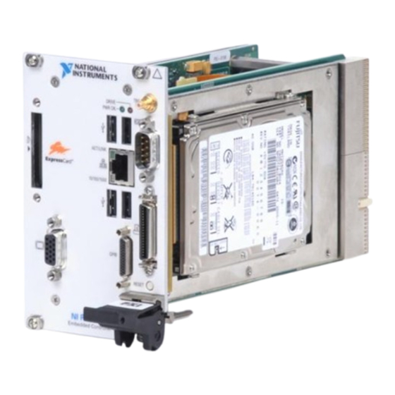
The NI PXI-8195 has a 1.5 GHz processor, all the standard I/O, and a 30 GB (or larger) hard drive. The NI PXI-8196 has a 2.0 GHz processor, all the standard I/O, and a 30 GB (or larger) hard drive. It also has a PCI-based GPIB controller and an ExpressCard/34 expansion slot. - Page 12 Socket 479 CPU is the socket definition for the Intel Pentium M processor families. • The SO-DIMM block consists of two 64-bit DDR2 SDRAM sockets that can hold up to 1 GB each. © National Instruments Corporation NI PXI-8195/8196 User Manual...
-
Page 13: National Instruments Software
• The ExpressCard/34 slot accommodates an ExpressCard/34 module. National Instruments Software National Instruments has developed several software kits you can use with the NI PXI-8195/8196. NI-DAQ has an extensive library of functions that you can call from your application programming environment. These functions include routines... - Page 14 Chapter 1 Introduction You also can use the National Instruments LabVIEW, Measurement Studio, ™ ™ and LabWindows /CVI application programs and instrument drivers to ease your programming task. These standardized programs match the modular virtual instrument capability of PXI and can reduce your PXI software development time.
-
Page 15: Installation And Configuration
Touch the metal part of the case to discharge any static electricity that might be on your clothes or body. Remove the protective plastic covers from the four bracket-retaining screws as shown in Figure 2-1. © National Instruments Corporation NI PXI-8195/8196 User Manual... - Page 16 Chapter 2 Installation and Configuration 1 Protective Screw Cap (4X) Figure 2-1. Removing Protective Screw Caps Make sure the injector/ejector handle is in its downward position. Align the NI PXI-8195/8196 with the card guides on the top and bottom of the system controller slot. Caution Do not raise the injector/ejector handle as you insert the NI PXI-8195/8196.
- Page 17 What if the NI PXI-8195/8196 does not boot? section of Chapter 5, Troubleshooting. Figure 2-2 shows an NI PXI-8196 installed in the system controller slot of a National Instruments PXI-1042 chassis. You can place PXI devices in any other slot.
-
Page 18: How To Remove The Controller From The Pxi Chassis
Chapter 2 Installation and Configuration How to Remove the Controller from the PXI Chassis The NI PXI-8195/8196 controller is designed for easy handling. To remove the unit from the PXI chassis, complete the following steps: Power off the chassis. Remove the bracket-retaining screws in the front panel. Press the injector/ejector handle down. -
Page 19: Main Setup Menu
However, if an IDE/ATA device is not autodetected properly, you can specify it manually by pressing <Enter> on an item. • System Information—This setting displays a screen containing important system information about the NI PXI-8195/8196 controller. © National Instruments Corporation NI PXI-8195/8196 User Manual... -
Page 20: Advanced Setup Menu
Chapter 2 Installation and Configuration DMI Event Logging Submenu Major errors that occur during the BIOS booting process are stored in battery-backed memory on the controller, and remain there until you view and clear them using this submenu. This logging capability allows a system administrator to detect the historical occurrence of faults on a controller. - Page 21 Usually, the default setting works for all applications. However, if a parallel port device specifically requires a nondefault setting, you can change it here. The default is Bidirectional, for full IEEE 1284 capabilities. © National Instruments Corporation NI PXI-8195/8196 User Manual...
-
Page 22: Pxi Setup Menu
Chapter 2 Installation and Configuration Legacy USB Support—Use this setting to use a USB keyboard and • mouse as if they were standard PS/2-style peripherals. You must enable this setting to use these devices in operating systems with no USB support and to boot from a USB floppy or CD-ROM. -
Page 23: Labview Rt Options Setup Menu
IDE 0—The internal IDE hard drive, connected to IDE Channel 0 master. • USB HDD—A USB based flash drive or hard disk drive. • USB CDROM—A USB based CD-ROM drive. • USB FDC—A USB based floppy disk drive. © National Instruments Corporation NI PXI-8195/8196 User Manual... -
Page 24: Exiting Bios Setup
Chapter 2 Installation and Configuration PCI SCSI—A SCSI drive (hard disk drive or CD-ROM) connected • through a SCSI controller in the PXI chassis. • PCI LAN—A PXE Network boot device, if PXE Network Boot is enabled on the Advanced menu. •... -
Page 25: System Cmos
Wait one second. Move the jumper back to pins 1–2. Reinstall the controller in the chassis. Caution Do not leave the jumper on pins 2–3. Doing so decreases battery life. Also, the controller will not boot. © National Instruments Corporation 2-11 NI PXI-8195/8196 User Manual... -
Page 26: Labview Rt Configuration Switches
Chapter 2 Installation and Configuration Normal Operation (Default) 2 Clear CMOS Contents 3 Pin 1 Figure 2-3. Clearing the CMOS Contents LabVIEW RT Configuration Switches Use the LabVIEW RT configuration switches to configure LabVIEW RT if it is installed on the controller. If you are not using LabVIEW RT, these switches should remain in the OFF position. - Page 27 The switches are shown in the OFF position. 1 Switch 1—Boot LabVIEW RT 3 Switch 3—Disable Startup VI 2 Switch 2—Boot Safe Mode 4 Switch 4—Reset IP Address Figure 2-4. LabVIEW RT Configuration Switches © National Instruments Corporation 2-13 NI PXI-8195/8196 User Manual...
-
Page 28: Drivers And Software
National Instruments software manuals, all in Adobe Acrobat format. To access any manual, change your directory to and list the contents of that directory. -
Page 29: Upgrading Ram
1 GB, 128 MB × 64, CL 4, 1.18 in. max Note National Instruments has tested and verified that the DDR2 SO-DIMMs we sell work with the NI PXI-8195/8196. We recommend you purchase your DDR2 SO-DIMM modules from National Instruments. Other off-the-shelf DDR2 SO-DIMM modules are not guaranteed to work properly. -
Page 30: Hard Drive Recovery
Chapter 2 Installation and Configuration 1 DDR2 SO-DIMM Module 2 DDR2 SO-DIMM Socket Figure 2-5. Installing a DDR2 SO-DIMM in an NI PXI-8195/8196 Controller Hard Drive Recovery NI PXI-8195/8196 controllers include Phoenix Technologies Ltd. Firstware tools, either Recover or Vault, or both. These tools allow you to recover the original factory condition of the hard disk from a small protected area of your hard drive. -
Page 31: Installing An Os
As an alternative to a USB CD-ROM drive, you can use an external SCSI CD-ROM with a PXI-SCSI adapter. Note For additional assistance with installing or changing an operating system, refer to KnowledgeBase 2ZKC02OK at ni.com/support © National Instruments Corporation 2-17 NI PXI-8195/8196 User Manual... -
Page 32: Front Panel Connectors
Routing PXI triggers to (SMB) or from the backplane trigger bus GPIB device GPIB General-Purpose 8196 only (25-pin Micro D) Interface Bus, IEEE 488.2 ExpressCard/34 ExpressCard/34 slot ExpressCard/34 8196 only module Expansion © National Instruments Corporation NI PXI-8195/8196 User Manual... -
Page 33: Front Panel
I/O Information Front Panel Figure 3-1 shows the front panel layout and dimensions of the NI PXI-8196, and Figure 3-2 shows the front panel layout and dimensions of the NI PXI-8195. Dimensions are in inches [millimeters]. 4.39 [111.5] 3.84 [97.5] 3.55 [90.2]... -
Page 34: Vga
Figure 3-3 shows the location and pinouts for the VGA connector on the NI PXI-8195/8196. Table 3-2 lists and describes the VGA connector signals. AMP manufactures a mating connector with part numbers 748364-1 (housing) and 748333-2 (pin contact). © National Instruments Corporation NI PXI-8195/8196 User Manual... - Page 35 Chapter 3 I/O Information Figure 3-3. VGA Connector Location and Pinout Table 3-2. VGA Connector Signals Signal Name Signal Description Green Blue Not Connected Ground Ground Ground Ground Ground Not Connected Serial Data HSync Horizontal Sync VSync Vertical Sync Serial Clock NI PXI-8195/8196 User Manual ni.com...
-
Page 36: Com1
Signal Name Signal Description DCD* Data Carrier Detect RXD* Receive Data TXD* Transmit Data DTR* Data Terminal Ready Ground DSR* Data Set Ready RTS* Ready to Send CTS* Clear to Send Ring Indicator © National Instruments Corporation NI PXI-8195/8196 User Manual... -
Page 37: Ethernet
Chapter 3 I/O Information Ethernet Figure 3-5 shows the location and pinouts for the Ethernet connector on the NI PXI-8195/8196. Table 3-4 lists and describes the Ethernet connector signals. AMP manufactures a mating connector, part number 554739-1. Ethernet Figure 3-5. Ethernet Connector Location and Pinout Table 3-4. -
Page 38: Parallel Port
Figure 3-6 shows the location and pinouts for the IEEE 1284 (parallel) connector on the NI PXI-8195/8196. Table 3-6 lists and describes the IEEE 1284 connector signals. Parallel port adapter cables are available from National Instruments, part number 777169-01. Parallel Port Figure 3-6. - Page 39 Chapter 3 I/O Information Table 3-6. Parallel Port Connector Signals Default Configuration (LPT) Signal Name Signal Description BUSY Device Busy SLCT Select ACK* Acknowledge FAULT*(ERROR*) Fault PAPEREND Paper End Data Bit 0 Data Bit 1 PD 2 Data Bit 2 Data Bit 3 Data Bit 4 Data Bit 5...
-
Page 40: Universal Serial Bus
AMP manufactures a USB mating connector, part number 787633. Figure 3-7. USB Connector Location and Pinout Table 3-7. USB Connector Signals Signal Name Signal Description Cable Power (+5 V) –Data USB Data– +Data USB Data+ Ground © National Instruments Corporation NI PXI-8195/8196 User Manual... -
Page 41: Trigger
Chapter 3 I/O Information Trigger The TRG connector is the software-controlled trigger connection for routing PXI triggers to or from the backplane trigger bus. Figure 3-8 shows the TRG connector location on the NI PXI-8195/8196. Table 3-8 lists and describes the trigger connector signals. Figure 3-8. -
Page 42: Gpib (Ieee 488.2)
I/O Information GPIB (IEEE 488.2) Figure 3-9 shows the location and pinouts for the GPIB connector on the NI PXI-8196. Table 3-9 lists and describes the GPIB connector signals. ITT Canon manufactures a GPIB mating connector, part number MDSM-25SC-Z11-V51. GPIB Figure 3-9. -
Page 43: Expresscard/34 Slot
18–25 Logic Ground ExpressCard/34 Slot The NI PXI-8196 controller is equipped with an ExpressCard/34 slot on the front panel, which provides I/O expansion and options for removable storage. Figure 3-10 shows the location and pinouts for the ExpressCard/34 slot on the NI PXI-8196. - Page 44 REFCLK– Reference Clock – REFCLK+ Reference Clock + Ground PERn0 PE Data Receive – PERp0 PE Data Receive + Ground PETn0 PE Data Transmit – PETp0 PE Data Transmit + Ground © National Instruments Corporation 3-13 NI PXI-8195/8196 User Manual...
-
Page 45: Front Panel Features
Chapter 3 I/O Information Front Panel Features The NI PXI-8195/8196 has the following front-panel features: • A system reset pushbutton (press the button to generate a reset to the controller) • Two front panel LEDs that show PC status – The POWER OK LED indicates the power status of the controller. -
Page 46: Common Configuration Questions
The internal IDE hard drive • An external SCSI hard drive or CD-ROM if an SCSI adapter, such as the PXI-8214, is used • A network PXE server on the same subnet © National Instruments Corporation NI PXI-8195/8196 User Manual... -
Page 47: Cables And Connections
The NI PXI-8195/8196 has no PS/2 connector, and you need to use a USB Y-splitter cable as shown in Figure 4-1, or a similar device, to connect both a PS/2 mouse and PS/2 keyboard. National Instruments Part Number 763608-01 is such a cable and is available through the online catalog at ni.com/products... -
Page 48: Software Driver Installation
GPIB driver in the Device Manager. If you need more assistance, refer ni.com/support/install Note Click the Scan for Hardware Changes in the Device Manager button to force re-detection of the GPIB hardware after installing the driver. © National Instruments Corporation NI PXI-8195/8196 User Manual... -
Page 49: Chassis Configuration
Chapter 4 Common Configuration Questions How do I install software from a CD? The compact size of the NI PXI-8195/8196 does not allow for an integrated CD-ROM drive. If you are using Windows XP, you have the following options: • USB CD-ROM—Windows XP supports installing from a USB CD-ROM using a bootable installation CD. -
Page 50: Basic Pxi System Configuration
Identify As submenu. Further expanding the PXI System branch shows all devices in the system that can be recognized by NI-VISA. When your controller and all your chassis are identified, the required file is complete. pxisys.ini © National Instruments Corporation NI PXI-8195/8196 User Manual... -
Page 51: Upgrade Information
1 GB, 128 MB × 64, CL 4, 1.18 in. max Note National Instruments has tested and verified that the DDR2 SO-DIMMs we sell work with the NI PXI-8195/8196. We recommend you purchase your DDR2 SO-DIMM modules from National Instruments. Other off-the-shelf DDR2 SO-DIMM modules are not guaranteed to work properly. - Page 52 A USB floppy drive will not work with Windows NT4, but will work with Windows 2000 or Windows XP. Refer to the Boot Options section for more information. A USB floppy drive is available from National Instruments, part number 778492-02. © National Instruments Corporation NI PXI-8195/8196 User Manual...
-
Page 53: Pxi Configuration
Chapter 4 Common Configuration Questions PXI Configuration How do I use the SMB trigger on the front panel? For details, refer to the PXI Features section of Chapter 2, Installation and Configuration. Why doesn’t the NI PXI-8195/8196 work with the PXI-8220? A serialized IRQ conflict with the PXI-8220 and the NI PXI-8195/8196 prevents PC cards using ISA interrupts from working with the NI PXI-8195/8196 controllers. -
Page 54: Troubleshooting
Does your monitor work with a different PC? If it hangs, note the last screen output that you saw for reference when consulting National Instruments technical support. • What has changed about the system? Did you recently move the... - Page 55 Chapter 5 Troubleshooting My controller boots fine until I get to Windows, at which point I cannot read the screen. This may include garbled output, white screen, black screen, or an out of synch message from the monitor. This problem usually results from having the video card output set past the limits of the monitor.
- Page 56 Do not leave the jumper on pins 2–3. Doing so decreases battery life. Also, the controller will not boot. 1 Normal Operation (Default) 2 Clear CMOS Contents 3 Pin 1 Figure 5-1. Clearing the CMOS Contents © National Instruments Corporation NI PXI-8195/8196 User Manual...
-
Page 57: Appendix A Specifications
(3.2 in. × 5.1 in. × 8.5 in.) Slot requirements ........One system slot plus three controller expansion slots Compatibility ......... Fully compatible with PXI specification Weight ............ 0.77 Kg (1.7 lb) typical © National Instruments Corporation NI PXI-8195/8196 User Manual... - Page 58 NI PXI-8195/8196 Ambient temperature range .....–20 to 65 °C (Tested in accordance with IEC-60068-2-1 and IEC-60068-2-2.) NI PXI-8196 Extended Temp. Option Ambient temperature range .....–40 to 85 °C (Tested in accordance with IEC-60068-2-1 and IEC-60068-2-2.) Relative humidity range......5% to 95% noncondensing (Tested in accordance with IEC-60068-2-56.)
- Page 59 FCC Part 15A above 1 GHz Immunity..........EN 61326:1997 + A2:2001, Table 1 EMC ............CE, C-Tick, and FCC Part 15 (Class A) compliant Note For full EMC compliance, operate this device with shielded cabling. © National Instruments Corporation NI PXI-8195/8196 User Manual...
- Page 60 Appendix A Specifications CE Compliance This product meets the essential requirements of applicable European Directives, as amended for CE marking, as follows: Low-Voltage Directive (safety)....73/23/EEC Electromagnetic Compatibility Directive (EMC) ........89/336/EEC Note Refer to the Declaration of Conformity (DoC) for this product for any additional regulatory compliance information.
- Page 61 Technical Support and Professional Services Visit the following sections of the National Instruments Web site at for technical support and professional services: ni.com • Support—Online technical support resources at ni.com/support include the following: – Self-Help Resources—For answers and solutions, visit the...
- Page 62 Appendix B Technical Support and Professional Services If you searched and could not find the answers you need, contact ni.com your local office or NI corporate headquarters. Phone numbers for our worldwide offices are listed at the front of this manual. You also can visit the Worldwide Offices section of to access the branch ni.com/niglobal...
- Page 63 Glossary Symbol Prefix Value nano –9 µ micro – 6 –3 milli kilo mega giga tera Symbols ° Degrees. Ω Ohms. Percent. Amperes. Alternating Current. ASIC Application-specific integrated circuit. © National Instruments Corporation NI PXI-8195/8196 User Manual...
- Page 64 Glossary Bytes. backplane An assembly, typically a printed circuit board, with connectors and signal paths that bus the connector pins. BIOS Basic Input/Output System—BIOS functions are the fundamental level of any PC or compatible computer. BIOS functions embody the basic operations needed for successful use of the computer’s hardware resources.
- Page 65 Hertz—Cycles per second. Input/output—The techniques, media, and devices used to achieve communication between machines and users. Integrated Drive Electronics—Hard disk and built-in controller. IEEE Institute of Electrical and Electronics Engineers. © National Instruments Corporation NI PXI-8195/8196 User Manual...
- Page 66 Glossary Inches. instrument driver A set of routines designed to control a specific instrument or family of instruments, and any necessary related files for LabWindows/CVI or LabVIEW. interrupt A means for a device to request service from another device. interrupt level The relative priority at which a device can interrupt.
- Page 67 Glossary NI-488 or NI-488.2 The National Instruments software for GPIB systems. NI-DAQ The National Instruments software for data acquisition instruments. NI-VISA The National Instruments implementation of the VISA standard—An interface-independent software that provides a unified programming interface for VXI, GPIB, and serial instruments.
- Page 68 Glossary resource Hardware settings used by devices in a computer system, including ISA interrupt level, DMA channel, and I/O address. Root mean squared. See also Real Time Clock—An electronic circuit that maintains the time of day and also can provide timing signals for timesharing operations. Seconds.
- Page 69 5-2 installing, 2-15, 4-6 COM1 connector figure, 2-16, 4-7 connector locations and pinout (figure), 3-5 DDR2 SO-DIMMs, from National Instruments connector signals (table), 3-5 (note), 2-15, 4-6 common configuration questions Declaration of Conformity (NI resources), B-1...
- Page 70 MAX (figure), 4-5 (figure), 3-12 injector/ejector handle position ExpressCard/34, 3-12 (caution), 2-2 NI PXI-8196 installed in a PXI chassis (figure), 2-3 procedure, 2-1 files and directories installed on hard removing NI PXI-8195/8196 from PXI drive, 2-14...
- Page 71 3-1 os directory, 2-14 COM1 connector and signals, 3-5 OS installation ExpressCard/34 connector and from CD-ROM, 2-17 signals, 3-12 GPIB (IEEE 488.2) connector and signals, 3-11 parallel port connector and signals, 3-7 © National Instruments Corporation NI PXI-8195/8196 User Manual...
- Page 72 2-14 connector location and pinout installing from CD-ROM, 4-4 (figure), 3-7 LabVIEW, 1-5 connector signals (table), 3-8 National Instruments software, 1-4 overview (table), 3-1 NI-DAQ, 1-4 PCI bus, standard for desktop computer NI-VISA, 1-4 designs, 1-1...
- Page 73 4-3 using with PS/2 mouse and keyboard, 2-3 connector signals (table), 3-4 location and pinout (figure), 3-4 overview (table), 3-1 video, 3-1 See also VGA driver installation, 4-3 © National Instruments Corporation NI PXI-8195/8196 User Manual...
Need help?
Do you have a question about the NI PXI-8196 and is the answer not in the manual?
Questions and answers