National Instruments PXI 1000B User Manual
Hide thumbs
Also See for PXI 1000B:
- Installation manual (12 pages) ,
- Additional information (6 pages) ,
- User manual (79 pages)

Related Manuals for National Instruments PXI 1000B


Summary of Contents for National Instruments PXI 1000B
- Page 1 ™ -1000B User Manual PXI-1000B User Manual February 1999 Edition Part Number 321710C-01...
- Page 2 Spain (Madrid) 91 640 0085, Spain (Barcelona) 93 582 0251, Sweden 08 587 895 00, Switzerland 056 200 51 51, Taiwan 02 2377 1200, United Kingdom 01635 523545 For further support information, see the Technical Support Resources appendix of this manual. © Copyright 1997, 1999 National Instruments Corporation. All rights reserved.
- Page 3 90 days from date of shipment, as evidenced by receipts or other documentation. National Instruments will, at its option, repair or replace software media that do not execute programming instructions if National Instruments receives notice of such defects during the warranty period.
- Page 4 This device complies with the FCC rules only if used with shielded interface cables of suitable quality and construction. National Instruments used such cables to test this device and provides them for sale to the user. The use of inferior or nonshielded interface cables could void the user’s authority to operate the equipment under the...
- Page 5 Part Replacement—Only service this equipment with parts that are exact replacements, both electrically and mechanically. Contact National Instruments for replacement part information. Installation of parts with those that are not direct replacements may cause harm to personnel operating the mainframe. Furthermore, damage or fire may occur if replacement parts are unsuitable.
-
Page 6: Table Of Contents
Input Voltage Priority (DC-Capable Power Supply Only) ..........2-6 Installing the Battery Pack (DC-Capable Power Supply Only)........2-6 Charging the Battery Pack (DC-Capable Power Supply Only) ........2-6 Installing PXI Modules ....................2-7 Installing Filler Panels ....................2-9 Using the Chassis Initialization File ................2-9 © National Instruments Corporation PXI-1000B User Manual... - Page 7 PXI-1000B Mainframe Airflow Side View .......... 2-2 Figure 2-2. Installing PXI or CompactPCI Modules ..........2-8 Figure 2-3. Injector/Ejector Handle Position during Module Insertion ....2-9 Figure A-1. PXI-1000B Dimensions ................ A-9 PXI-1000B User Manual viii © National Instruments Corporation...
- Page 8 Table B-4. P2 (J2) Connector Pinout for the Star Trigger Slot ......B-5 Table B-5. P1 (J1) Connector Pinout for the Peripheral Slot .........B-6 Table B-6. P2 (J2) Connector Pinout for the Peripheral Slot .........B-7 © National Instruments Corporation PXI-1000B User Manual...
-
Page 9: About This Manual
Appendix B, Pinouts, describes the P1 and P2 connector pinouts for the PXI-1000B backplane. • Appendix C, Customer Communication, contains forms you can use to request help from National Instruments or to comment on our products and manuals. • Glossary lists abbreviations, acronyms, metric prefixes, mnemonics, symbols, and terms. -
Page 10: Related Documentation
Equipment Practice Customer Communication National Instruments wants to receive your comments on our products and manuals. We are interested in the applications you develop with our products, and we want to help if you have problems with them. To make it easy for you to contact us, this manual contains comment and configuration forms for you to complete. -
Page 11: Getting Started
PXI-1000B User Manual Floppy disk with Chassis Initialization file, chassis.ini Table 1-1. AC Power Cables Power Cable Reference Standards Standard 120 V (USA) ANSI C73.11/NEMA 5-15-P/IEC83 Switzerland 220 V Australia 240 V AS C112 © National Instruments Corporation PXI-1000B User Manual... -
Page 12: Optional Equipment
If you are missing any of the above items or if you have the incorrect power cord, contact National Instruments. Optional Equipment Contact National Instruments to order the following options for your PXI-1000B mainframe. Battery Pack and Cable for DC-Capable PXI-1000B A DC input capable power supply is optionally installed in your PXI-1000B mainframe at the factory. -
Page 13: Key Features
PXI-specific features. For example, you may want to use a standard CompactPCI network interface card in a PXI chassis. The signals on the P1 connector of the backplane meet the requirements of the CompactPCI specification for both the peripheral and system modules. © National Instruments Corporation PXI-1000B User Manual... -
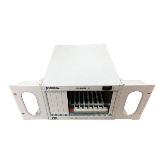
Page 14: Figure 1-1. Front View Of The Pxi-1000B Mainframe
6 Star Trigger Slot 2 Backplane Connectors 4 Removable Feet 7 System Controller Slot (Located in Slots 1-8) 5 Peripheral Slots 8 Controller Expansion Slots Figure 1-1. Front View of the PXI-1000B Mainframe PXI-1000B User Manual © National Instruments Corporation... -
Page 15: Figure 1-2. Rear View Of The Ac-Only Pxi-1000B Mainframe
1 Module Cooling Air Outlets 3 Remote Power Status and Inhibit Connector 5 Circuit Breake 2 Fan Speed Selector 4 Chassis Ground Screw 6 Universal AC Input Figure 1-2. Rear View of the AC-Only PXI-1000B Mainframe © National Instruments Corporation PXI-1000B User Manual... -
Page 16: System Controller Slot
ST functionality that can provide individual triggers to all other peripherals. However, if you do not require advanced trigger functionality, you can install any standard peripheral module into this slot. PXI-1000B User Manual © National Instruments Corporation... -
Page 17: Peripheral Slots
This method is a flexible way to define local bus functionality that is not limited by hardware keying. Star Triggers Local Local Local PCI Arbitration and Clock Signals Figure 1-4. PXI Local Bus and Star Trigger Routing © National Instruments Corporation PXI-1000B User Manual... -
Page 18: Trigger Bus
Star Trigger Slot. (See Table B-1, P1 (J1) Connector Pinout for the System Controller Slot, in Appendix B, Pinouts.) Sourcing an external clock on this pin automatically disables the backplane’s 10 MHz source. PXI-1000B User Manual © National Instruments Corporation... -
Page 19: Installation, Configuration, And Operation
(air inlets) and the air outlet apertures along both sides of the mainframe have adequate ventilation. Keep other equipment a minimum of 3.0 in. (76.2 mm) away from the air inlets and outlets. © National Instruments Corporation PXI-1000B User Manual... -
Page 20: Rack Mounting
Rack Mounting Rack-mount applications require the optional rack-mount kit available from National Instruments. Refer to the instructions supplied with the rack-mount kit to install your PXI-1000B in an instrument rack. Note You may wish to remove the feet from your PXI-1000B when rack mounting. -
Page 21: Connecting Safety Ground
You can use a digital voltmeter to ensure all voltage levels in your PXI-1000B are within the allowable limits. Referring to Table 2-1, connect one lead of the voltmeter to a supply pin on the remote power monitoring © National Instruments Corporation PXI-1000B User Manual... -
Page 22: Remote Power Monitoring And Inhibiting Interface
9-pin D-sub connector located on the rear panel. Table 2-2 shows the pinout of the DB-9 connector. Table 2-2. DB-9 Connector Pinout DB-9 Pin Signal Logic Ground +5 V Inhibit Return (DC-capable supply only) +3.3 V PXI-1000B User Manual © National Instruments Corporation... -
Page 23: Power Supply Status Indication (Dc-Capable Power Supply Only)
Mainframe, for a diagram of the Power Supply Status LED. Table 2-3. Power Supply Status Indication, DC Only Power Source Power Switch Mode Status LED AC or External DC Input Standby Green AC or External DC Input Bright Green © National Instruments Corporation PXI-1000B User Manual... -
Page 24: Input Voltage Priority (Dc-Capable Power Supply Only)
The optional battery pack is charged when either the AC power or the external DC power is connected, regardless of the front STANDBY/ON switch position. The power supply has circuitry to prevent the battery pack from overcharging. PXI-1000B User Manual © National Instruments Corporation... -
Page 25: Installing Pxi Modules
(top and bottom), as shown in Figure 2-2. Slide the module to the rear of the mainframe (making sure that the injector/ejector handle is pushed down as shown in Figure 2-3). © National Instruments Corporation PXI-1000B User Manual... -
Page 26: Figure 2-2. Installing Pxi Or Compactpci Modules
Secure the module’s front panel to the mainframe using the module’s front-panel mounting screws. 1 PXI-1000B Chassis 3 PXI Board 5 Injector/Ejector Rail 2 PXI-8156B System Controller 4 Injector/Ejector Handle Figure 2-2. Installing PXI or CompactPCI Modules PXI-1000B User Manual © National Instruments Corporation... -
Page 27: Installing Filler Panels
ASCII text. The system integrator can .ini read the file, and configuration utilities and device drivers can also .ini use this file. The PXI-1000B chassis initialization file, chassis.ini is included on the diskette for your PXI-1000B. © National Instruments Corporation PXI-1000B User Manual... -
Page 28: Service Interval
Refer to your module user documentation for information on cleaning the individual CompactPCI or PXI modules. Caution Always power-off the mainframe and disconnect the power cord before cleaning or servicing the mainframe. © National Instruments Corporation PXI-1000B User Manual... -
Page 29: Interior Cleaning
Clean the fan filters by washing them in a mild soap solution and then vacuuming or blowing air through them. Rinse the filters with water and allow them to dry before reinstalling them on the mainframe. PXI-1000B User Manual © National Instruments Corporation... -
Page 30: Resetting The Ac Mains Circuit Breaker
The over-current condition that caused the circuit breaker to trip may be due to a faulty CompactPCI or PXI module. Refer to the documentation that was supplied with the modules for troubleshooting your modules. © National Instruments Corporation PXI-1000B User Manual... -
Page 31: Troubleshooting The Pxi-1000B
Notice: The battery is charged whether battery pack may be discharged. the power switch is in the On or Standby position. Power supply has failed. Contact National Instruments. PXI-1000B User Manual © National Instruments Corporation... -
Page 32: Appendix A Specifications
CompactPCI/PXI backplane. The rear-panel D-sub connector facilitates remote inhibiting operation. The (standby) switch must be in the On position prior to use of remote inhibit. The power cord provides main power disconnect. © National Instruments Corporation PXI-1000B User Manual... -
Page 33: Table A-2. Dc Output Specifications For Ac-Only Power Supply
Replacement in under 5 minutes MTTR Table A-3. AC Input Specifications for DC-Capable Power Supply Characteristic Description Input Voltage Range 85–265 VAC Input Frequency Range 45 to 65 Hz Over-Current Protection 5 A circuit breaker PXI-1000B User Manual © National Instruments Corporation... -
Page 34: Table A-4. Dc Input Specifications For Dc-Capable Power Supply
CompactPCI/PXI backplane. The rear-panel D-sub connector facilitates remote inhibiting operation. The front (standby) switch must be in the On position prior to use of remote inhibit. The power cord provides main power disconnect. © National Instruments Corporation PXI-1000B User Manual... -
Page 35: Table A-5. Dc Output Specifications For Dc-Capable Power Supply
All outputs have over-current protection. Restart by ON/STANDBY switch. Over-Voltage Protection 20% to 35% above output voltage causes supply shutdown. Restart by ON/STANDBY switch. Power Supply/Fan Unit Replacement in under 5 minutes MTTR PXI-1000B User Manual © National Instruments Corporation... -
Page 36: Table A-6. Cooling Specifications
Power Supply/Fan Unit Replacement in under 5 minutes Safety Table A-7. Safety Specifications Characteristic Description Safety Characteristics UL 3111-1, IEC 1010-1, CSA 22.2 No. 1010.1 Installation Category II Pollution Degree 2 Safety Class 1 © National Instruments Corporation PXI-1000B User Manual... -
Page 37: Table A-8. Environmental Specifications
2 km (1.24 mi) * Random vibration profiles were developed in accordance with MIL-T-28800E CLASS 3 and MIL-STD-810E Method 514 Test levels exceed those recommended in MIL-STD-810E for Category 1 (Basic Transportation), Figures 514.4-1 through 514.4-3. PXI-1000B User Manual © National Instruments Corporation... -
Page 38: Table A-9. Backplane Specifications
Accepts both PXI and CompactPCI (PICMG 2.0 R2.1) 3U modules. Backplane Bare-Board UL 94 V-0 recognized Material (File No. E 116551) Backplane Connectors Conform to IEC 917 and IEC 1076-4-101, and are UL 94 V-0 rated © National Instruments Corporation PXI-1000B User Manual... -
Page 39: Table A-10. Mechanical Specifications
8.6 kg (19 lb.) Maximum Module Weight 1.8 kg (4 lb.) Materials Sheet Aluminum (5052-H32) and Cold Rolled Steel Finish Unpainted Aluminum Conductive Clear Iridite Cold Rolled Steel Clear Chromate Zinc Plating Paint Polyurethane Enamel PXI-1000B User Manual © National Instruments Corporation... -
Page 40: Figure A-1. Pxi-1000B Dimensions
Note that the front and rear chassis mounting holes (size M4) are symmetrical. 7.00 in. 10.64 in. 14.90 in. 1.823 in. .78 in. 1.08 in. 1.844 in. 3.541 in. .57 in. Figure A-1. PXI-1000B Dimensions © National Instruments Corporation PXI-1000B User Manual... -
Page 41: Appendix B Pinouts
Table B-4 shows the P2 (J2) connector pinout for the Star Trigger slot. Table B-5 shows the P1 (J1) connector pinout for the peripheral slots. Table B-6 shows the P2 (J2) connector pinout for the peripheral slots. Note PXI signals are shown in boldface. © National Instruments Corporation PXI-1000B User Manual... -
Page 42: Table B-1. P1 (J1) Connector Pinout For The System Controller Slot
3.3V AD[20] AD[19] C/BE[3]# IDSEL AD[23] AD[22] AD[26] V(I/O) AD[25] AD[24] AD[30] AD[29] AD[28] AD[27] REQ# 3.3V AD[31] BRSVP1A5 BRSVP1B5 RST# GNT# BRSVP1A4 V(I/O) INTP INTS INTA# INTB# INTC# INTD# –12V TRST# +12V PXI-1000B User Manual © National Instruments Corporation... -
Page 43: Table B-2. P2 (J2) Connector Pinout For The System Controller Slot
AD[56] AD[55] AD[54] AD[53] AD[59] V(I/O) AD[58] AD[57] AD[63] AD[62] AD[61] AD[60] C/BE[5]# V(I/O) C/BE[4]# PAR64 V(I/O) PXI_BRSVB4 C/BE[7]# C/BE[6]# CLK4 GNT3# REQ4# GNT4# CLK2 CLK3 SYSEN# GNT2# REQ3# CLK1 REQ1# GNT1# REQ2# © National Instruments Corporation PXI-1000B User Manual... -
Page 44: Table B-3. P1 (J1) Connector Pinout For The Star Trigger Slot
3.3V AD[20] AD[19] C/BE[3]# IDSEL AD[23] AD[22] AD[26] V(I/O) AD[25] AD[24] AD[30] AD[29] AD[28] AD[27] REQ# 3.3V AD[31] BRSVP1A5 BRSVP1B5 RST# GNT# BRSVP1A4 V(I/O) INTP INTS INTA# INTB# INTC# INTD# –12V TRST# +12V PXI-1000B User Manual © National Instruments Corporation... -
Page 45: Table B-4. P2 (J2) Connector Pinout For The Star Trigger Slot
AD[56] AD[55] AD[54] AD[53] AD[59] V(I/O) AD[58] AD[57] AD[63] AD[62] AD[61] AD[60] C/BE[5]# V(I/O) C/BE[4]# PAR64 V(I/O) PXI_BRSVB4 C/BE[7]# C/BE[6]# PXI_LBR7 PXI_LBR8 PXI_LBR9 PXI_LBR10 PXI_LBR11 PXI_LBR12 SYSEN# PXI_STAR7 PXI_STAR8 PXI_STAR9 PXI_STAR10 PXI_STAR11 PXI_STAR12 © National Instruments Corporation PXI-1000B User Manual... -
Page 46: Table B-5. P1 (J1) Connector Pinout For The Peripheral Slot
3.3V AD[20] AD[19] C/BE[3]# IDSEL AD[23] AD[22] AD[26] V(I/O) AD[25] AD[24] AD[30] AD[29] AD[28] AD[27] REQ# 3.3V AD[31] BRSVP1A5 BRSVP1B5 RST# GNT# BRSVP1A4 V(I/O) INTP INTS INTA# INTB# INTC# INTD# –12V TRST# +12V PXI-1000B User Manual © National Instruments Corporation... -
Page 47: Table B-6. P2 (J2) Connector Pinout For The Peripheral Slot
AD[56] AD[55] AD[54] AD[53] AD[59] V(I/O) AD[58] AD[57] AD[63] AD[62] AD[61] AD[60] C/BE[5]# V(I/O) C/BE[4]# PAR64 V(I/O) PXI_BRSVB4 C/BE[7]# C/BE[6]# PXI_LBR7 PXI_LBR8 PXI_LBR9 PXI_LBR10 PXI_LBR11 PXI_LBR12 SYSEN# PXI_LBL7 PXI_LBL8 PXI_LBL9 PXI_LBL10 PXI_LBL11 PXI_LBL12 © National Instruments Corporation PXI-1000B User Manual... -
Page 48: Appendix C Customer Communication
Customer Communication National Instruments offers technical support through electronic, fax, and telephone systems. The electronic services include our Web site, an FTP site, and a fax-on-demand system. If you have a hardware or software problem, please first try the electronic support systems. If the information... - Page 49 National Instruments has branch offices all over the world. Use the following list to find the technical support number for your country. If there is no National Instruments office in your country, contact the source from which you purchased your software to obtain support.
- Page 50 National Instruments for technical support helps our applications engineers answer your questions more efficiently. If you are using any National Instruments hardware or software products related to this problem, include the configuration forms from their user manuals. Include additional pages if necessary.
- Page 51 Complete a new copy of this form each time you revise your software or hardware configuration, and use this form as a reference for your current configuration. Completing this form accurately before contacting National Instruments for technical support helps our applications engineers answer your questions more efficiently.
- Page 52 Other Products List and describe all devices installed in your mainframe. Slot Manufacturer, Description, and Function...
- Page 53 Documentation Comment Form National Instruments encourages you to comment on the documentation supplied with our products. This information helps us provide quality products to meet your needs. Title: ™ -1000B User Manual Edition Date: February 1999 Part Number: 321710C-01 Please comment on the completeness, clarity, and organization of the manual.
-
Page 54: Glossary
–3 –2 centi- kilo- mega- Symbols ° Degrees ≥ Equal or greater than ≤ Equal or less than Percent Amperes Alternating current Ampere hours ANSI American National Standards Institute American Wire Gauge © National Instruments Corporation PXI-1000B User Manual... - Page 55 Direct current Emitter-coupled logic Electronic Industries Association Electromagnetic Compatibility Federal Communications Commission 1) grams 2) A measure of acceleration equal to 9.8 m/s GPIB General Purpose Interface Bus (IEEE 488) PXI-1000B User Manual © National Instruments Corporation...
- Page 56 IEEE Institute of Electrical and Electronics Engineers Mainframe peak current Inches Pounds Meters MTBF Mean time between failure MTTR Mean time to repair NEMA National Electrical Manufacturers Association PCI eXtensions for Instrumentation © National Instruments Corporation PXI-1000B User Manual...
- Page 57 Installing such a device into any other slot can damage the device, the VXIbus backplane, or both. Underwriter’s Laboratories Volts Volts alternating current Peak to peak voltage Watts PXI-1000B User Manual © National Instruments Corporation...
-
Page 58: Index
2-9 connector pinouts. See pinouts. FTP site, C-1 cooling air cooling of PXI-1000, 2-1 to 2-2 air intake (figure), 2-2 filler panel installation, 2-9 ground, connecting, 2-3 setting fan speed, 2-2 © National Instruments Corporation PXI-1000B User Manual... - Page 59 P2 (J2) connector pinouts (table), B-7 pinouts, B-1 DB-9 connector (table), 2-4 local bus P1 (J1) connector routing (figure), 1-7 peripheral slot (table), B-6 Star Trigger slot (table), B-4 system controller slot (table), B-2 PXI-1000B User Manual © National Instruments Corporation...
- Page 60 P2 (J2) connector pinouts (table), B-5 rack-mount kit, 1-2 status LED, 2-5 rearview of AC-only (figure), 1-5 system controller slot rearview of DC-capable (figure), 1-6 description, 1-6 safety ground, connecting, 2-3 P1 (J1) connector pinouts (table), B-2 © National Instruments Corporation PXI-1000B User Manual...
- Page 61 P2 (J2) connector pinouts (table), B-3 system reference clock, 1-8 unpacking the PXI-1000B, 1-1 testing power up, 2-3 voltages at power monitoring connector trigger bus, 1-8 (DB-9) (table), 2-4 troubleshooting the PXI-1000B (table), 3-4 PXI-1000B User Manual © National Instruments Corporation...
Need help?
Do you have a question about the PXI 1000B and is the answer not in the manual?
Questions and answers