Table of Contents
Advertisement
Quick Links
www.ti.com
User's Guide
ADS8332EVMV2-PDK Evaluation Module
Reed Kaczmarek
This user's guide describes the characteristics, operation, and use of the ADS8332 evaluation module (EVM)
performance demonstration kit (PDK). The ADS8332 is a low-power, 16-bit, 500k samples per-second (SPS)
successive approximation (SAR) analog-to-digital converter (ADC) with an 8-to-1 multiplexer (mux) input. Each
input channel on the device supports unipolar input ranges of 0 V to 4.096 V with single-supply operation. The
EVM-PDK eases the evaluation of ADS8332 device with hardware, software, and computer connectivity through
the universal serial bus (USB) interface. This user's guide includes complete circuit descriptions, schematic
diagrams, and a bill of materials.
SBAU251B – JULY 2017 – REVISED FEBRUARY 2023
Submit Document Feedback
ABSTRACT
Copyright © 2023 Texas Instruments Incorporated
Data Acquisition Products
ADS8332EVMV2-PDK Evaluation Module
1
Advertisement
Table of Contents

Subscribe to Our Youtube Channel
Related Manuals for Texas Instruments ADS8332EVMV2-PDK


Summary of Contents for Texas Instruments ADS8332EVMV2-PDK
- Page 1 (USB) interface. This user's guide includes complete circuit descriptions, schematic diagrams, and a bill of materials. SBAU251B – JULY 2017 – REVISED FEBRUARY 2023 ADS8332EVMV2-PDK Evaluation Module Submit Document Feedback Copyright © 2023 Texas Instruments Incorporated...
-
Page 2: Table Of Contents
Figure 5-3. ADS8332 Device Driver Installation Wizard Prompts....................Figure 5-4. LabVIEW Run-Time Engine Installation........................Figure 5-5. ADS8332EVM Folder Post-Installation........................Figure 6-1. ADS8332EVMV2-PDK Hardware Setup and LED Indicators..................14 Figure 6-2. Launch the ADS8332EVMV2 GUI Software......................Figure 6-3. EVM GUI Global Input Parameters......................... - Page 3 ® and Windows 8 ® are registered trademarks of Microsoft Corporation. All trademarks are the property of their respective owners. SBAU251B – JULY 2017 – REVISED FEBRUARY 2023 ADS8332EVMV2-PDK Evaluation Module Submit Document Feedback Copyright © 2023 Texas Instruments Incorporated...
-
Page 4: Overview
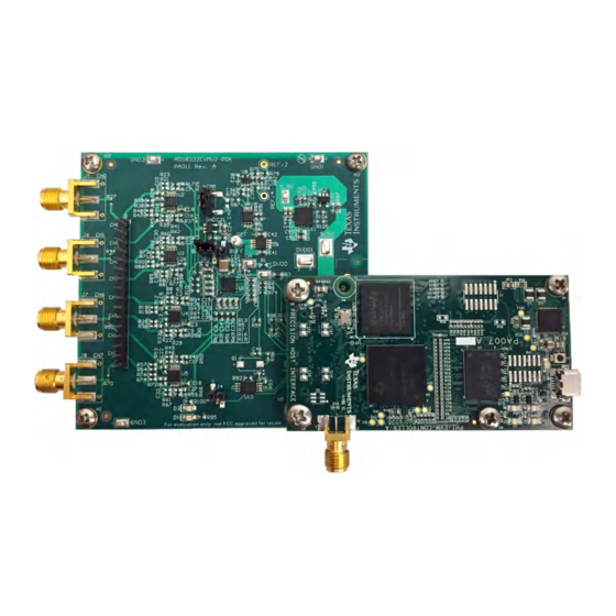
1 Overview The ADS8332EVMV2-PDK is a platform for evaluating the performance of the ADS8332 SAR ADC, which is an 8-channel, 16-bit, 4.096-V, multiplexed input ADC device. The evaluation kit includes the ADS8332EVMV2 board and the precision host interface (PHI) controller board that enables the accompanying computer software to communicate with the ADC over USB for data capture and analysis. -
Page 5: Evm Analog Interface
¢ £ 1500 pF 0.2-V Supply 40.2 1500 pF Figure 2-1. ADS8332EVMV2 Analog Input Connections for Channels IN0 to IN7 SBAU251B – JULY 2017 – REVISED FEBRUARY 2023 ADS8332EVMV2-PDK Evaluation Module Submit Document Feedback Copyright © 2023 Texas Instruments Incorporated... -
Page 6: Ads8332Evmv2 Onboard Reference
Figure 2-2. ADS8332 VOUT REF+ (PIN15) ¡ REF6041 FILT 1 µF 47 µF Figure 2-2. REF6041 4.096-V Onboard Reference Source ADS8332EVMV2-PDK Evaluation Module SBAU251B – JULY 2017 – REVISED FEBRUARY 2023 Submit Document Feedback Copyright © 2023 Texas Instruments Incorporated... -
Page 7: Digital Interfaces
There are two devices on the EVM with which the PHI communicates: the ADS8332 ADC (over serial interface) and the EEPROM (over I C). The EEPROM comes preprogrammed with the information required to configure and initialize the ADS8332EVMV2-PDK platform. After the hardware is initialized, the EEPROM is no longer used. 3.1 ADS8332 Digital Interface The ADS8332EVMV2-PDK communicates with the PHI controller through SPI connections. -
Page 8: Power Supplies
When using the ADS8332EVMV2 in conjunction with the PHI controller, the PHI controller supplies the AVDD and DVDD supply. Do not supply external power supply voltages. ADS8332EVMV2-PDK Evaluation Module SBAU251B – JULY 2017 – REVISED FEBRUARY 2023 Submit Document Feedback Copyright © 2023 Texas Instruments Incorporated... -
Page 9: Ads8332Evmv2-Pdk Initial Setup
Multiplexer output buffer Shunt on pins 1-2 MUXOUT and ADCIN EEPROM write enable Open Open enables write protect for the EEPROM SBAU251B – JULY 2017 – REVISED FEBRUARY 2023 ADS8332EVMV2-PDK Evaluation Module Submit Document Feedback Copyright © 2023 Texas Instruments Incorporated... -
Page 10: Evm Graphical User Interface (Gui) Software Installation
Download the latest version of the EVM GUI installer from the Tools and Software folder of the ADS8332EVMV2-PDK, and run the GUI installer to install the EVM GUI software. Administrator privileges on the PC are required in order to install the EVM software. Accept the license agreements and follow the on-screen... -
Page 11: Figure 5-3. Ads8332 Device Driver Installation Wizard Prompts
A notice may appear on the screen stating that Widows cannot verify the publisher of this driver software. Select Install this driver software anyway. SBAU251B – JULY 2017 – REVISED FEBRUARY 2023 ADS8332EVMV2-PDK Evaluation Module Submit Document Feedback Copyright © 2023 Texas Instruments Incorporated... -
Page 12: Figure 5-4. Labview Run-Time Engine Installation
Run-Time Engine, and may prompt for the installation of this software, as shown in Figure 5-4, if not already installed. Figure 5-4. LabVIEW Run-Time Engine Installation ADS8332EVMV2-PDK Evaluation Module SBAU251B – JULY 2017 – REVISED FEBRUARY 2023 Submit Document Feedback Copyright © 2023 Texas Instruments Incorporated... -
Page 13: Figure 5-5. Ads8332Evm Folder Post-Installation
ADS8332EVMV2-PDK Initial Setup After these installations, verify that C:\Program Files (x86)\Texas Instruments\ADS8332EVM is as shown in Figure 5-5. Figure 5-5. ADS8332EVM Folder Post-Installation SBAU251B – JULY 2017 – REVISED FEBRUARY 2023 ADS8332EVMV2-PDK Evaluation Module Submit Document Feedback Copyright © 2023 Texas Instruments Incorporated... -
Page 14: Ads8332Evmv2-Pdk Operation
LEDs D1 and D2 on the PHI starts blinking to indicate that the PHI is booted up and communicating with the PC. The resulting LED indicators are shown in Figure 6-1. Figure 6-1. ADS8332EVMV2-PDK Hardware Setup and LED Indicators 3. Double click on the ADS8332 EVM.exe file to launch the EVM GUI, as shown in Figure 6-2. -
Page 15: Evm Gui Global Settings For Adc Control
Figure 6-5 shows the time domain display when all eight channels are captured in auto channel select mode. SBAU251B – JULY 2017 – REVISED FEBRUARY 2023 ADS8332EVMV2-PDK Evaluation Module Submit Document Feedback Copyright © 2023 Texas Instruments Incorporated... -
Page 16: Figure 6-4. Time Domain Display: Manual
ADS8332EVMV2-PDK Operation www.ti.com Figure 6-4. Time Domain Display: Manual Figure 6-5. Time Domain Display: Auto ADS8332EVMV2-PDK Evaluation Module SBAU251B – JULY 2017 – REVISED FEBRUARY 2023 Submit Document Feedback Copyright © 2023 Texas Instruments Incorporated... -
Page 17: Spectral Analysis Tool
24-bit ADC. The None option corresponds to not using a window (or using a rectangular window) and is not recommended. SBAU251B – JULY 2017 – REVISED FEBRUARY 2023 ADS8332EVMV2-PDK Evaluation Module Submit Document Feedback Copyright © 2023 Texas Instruments Incorporated... -
Page 18: Histogram Tool
The histogram corresponding to a dc input is displayed on clicking on the Capture button, as shown in Figure 6-7: Figure 6-7. Histogram Analysis Tool ADS8332EVMV2-PDK Evaluation Module SBAU251B – JULY 2017 – REVISED FEBRUARY 2023 Submit Document Feedback Copyright © 2023 Texas Instruments Incorporated... -
Page 19: Linearity Analysis Tool
This analysis can take a couple of minutes to run and the evaluation board must remain undisturbed during the complete duration of the analysis. Figure 6-8. Linearity Analysis Tool SBAU251B – JULY 2017 – REVISED FEBRUARY 2023 ADS8332EVMV2-PDK Evaluation Module Submit Document Feedback Copyright © 2023 Texas Instruments Incorporated... -
Page 20: Input Amplifier Configurations
40.2 k 2.048 V 2.048 V ¥ To ADC ¦ 1500 pF REF/2 – Figure 6-9. Input Amplifier Configuration Examples ADS8332EVMV2-PDK Evaluation Module SBAU251B – JULY 2017 – REVISED FEBRUARY 2023 Submit Document Feedback Copyright © 2023 Texas Instruments Incorporated... -
Page 21: Bill Of Materials, Pcb Layout, And Schematics
RES, 0, 5%, 0.1 W, 0603 0603 CRCW06030000Z0EA Vishay-Dale R5, R6, R7, R9, R13, RES, 47, 5%, 0.063 W, 0402 CRCW040247R0 JNED Vishay-Dale R14, R16 0402 SBAU251B – JULY 2017 – REVISED FEBRUARY 2023 ADS8332EVMV2-PDK Evaluation Module Submit Document Feedback Copyright © 2023 Texas Instruments Incorporated... - Page 22 RF LDO Voltage RGW0020A TPS7A4700RGWR Texas Instruments Regulator, RGW0020A (VQFN-20) Nanopower Supervisory Circuits for Automotive, DBV0005A TPS3836E18DBVT Texas Instruments DBV0005A (SOT-23-5) ADS8332EVMV2-PDK Evaluation Module SBAU251B – JULY 2017 – REVISED FEBRUARY 2023 Submit Document Feedback Copyright © 2023 Texas Instruments Incorporated...
- Page 23 SMD, 2-Leads, Body 6x4 EVQPNF04M Panasonic NO, 0.05A, 12 V, SMD Test Point, Miniature, TP3, TP9 White Miniature Testpoint 5002 Keystone White, TH SBAU251B – JULY 2017 – REVISED FEBRUARY 2023 ADS8332EVMV2-PDK Evaluation Module Submit Document Feedback Copyright © 2023 Texas Instruments Incorporated...
-
Page 24: Pcb Layout
Figure 7-2. ADS8332EVMV2 PCB Layer 1: Top Layer Figure 7-4. ADS8332EVMV2 PCB Layer 3: Power Figure 7-3. ADS8332EVMV2 PCB Layer 2: GND Planes Plane ADS8332EVMV2-PDK Evaluation Module SBAU251B – JULY 2017 – REVISED FEBRUARY 2023 Submit Document Feedback Copyright © 2023 Texas Instruments Incorporated... -
Page 25: Figure 7-5. Ads8332Evmv2 Pcb Layer 4: Bottom Layer
Bill of Materials, PCB Layout, and Schematics Figure 7-6. ADS8332EVMV2 PCB: Bottom Overlay Figure 7-5. ADS8332EVMV2 PCB Layer 4: Bottom Layer SBAU251B – JULY 2017 – REVISED FEBRUARY 2023 ADS8332EVMV2-PDK Evaluation Module Submit Document Feedback Copyright © 2023 Texas Instruments Incorporated... -
Page 26: Schematics
10.0k REF+ 20.0k OUT_S OPA2320SAIDGSR OPA2320SAIDGSR 1500pF OUT_F 1.00k 10µF FILT GND_F GND_S 1µF REF6041IDGKR Figure 7-7. ADS8332EVMV2-PDK Schematic: ADC ADS8332EVMV2-PDK Evaluation Module SBAU251B – JULY 2017 – REVISED FEBRUARY 2023 Submit Document Feedback Copyright © 2023 Texas Instruments Incorporated... -
Page 27: Figure 7-8. Ads8332Evmv2-Pdk Schematic: Interface
3P2V Green R102 R103 R104 1P6V 0P8V TPS3836E18DBVT 0P4V 0P2V 0P1V R105 R106 R107 TPS7A4700RGWR Figure 7-8. ADS8332EVMV2-PDK Schematic: Interface SBAU251B – JULY 2017 – REVISED FEBRUARY 2023 ADS8332EVMV2-PDK Evaluation Module Submit Document Feedback Copyright © 2023 Texas Instruments Incorporated... -
Page 28: Figure 7-9. Ads8332Evmv2-Pdk Schematic: Hardware
These assemblies must be clean and free from flux a nd all contaminants. Use of no clean flux is not ac ceptable. Assembly Note These assemblies must comply with workmanship stand ards IPC-A-610 Class 2, unless otherwise specified. Figure 7-9. ADS8332EVMV2-PDK Schematic: Hardware ADS8332EVMV2-PDK Evaluation Module SBAU251B – JULY 2017 – REVISED FEBRUARY 2023 Submit Document Feedback Copyright ©... -
Page 29: Revision History
NOTE: Page numbers for previous revisions may differ from page numbers in the current version. Changes from Revision A (July 2017) to Revision B (February 2023) Page • Changed Input Amplifier Configuration Examples figure.................. SBAU251B – JULY 2017 – REVISED FEBRUARY 2023 ADS8332EVMV2-PDK Evaluation Module Submit Document Feedback Copyright © 2023 Texas Instruments Incorporated... - Page 30 STANDARD TERMS FOR EVALUATION MODULES Delivery: TI delivers TI evaluation boards, kits, or modules, including any accompanying demonstration software, components, and/or documentation which may be provided together or separately (collectively, an “EVM” or “EVMs”) to the User (“User”) in accordance with the terms set forth herein.
- Page 31 www.ti.com Regulatory Notices: 3.1 United States 3.1.1 Notice applicable to EVMs not FCC-Approved: FCC NOTICE: This kit is designed to allow product developers to evaluate electronic components, circuitry, or software associated with the kit to determine whether to incorporate such items in a finished product and software developers to write software applications for use with the end product.
- Page 32 www.ti.com Concernant les EVMs avec antennes détachables Conformément à la réglementation d'Industrie Canada, le présent émetteur radio peut fonctionner avec une antenne d'un type et d'un gain maximal (ou inférieur) approuvé pour l'émetteur par Industrie Canada. Dans le but de réduire les risques de brouillage radioélectrique à...
- Page 33 www.ti.com EVM Use Restrictions and Warnings: 4.1 EVMS ARE NOT FOR USE IN FUNCTIONAL SAFETY AND/OR SAFETY CRITICAL EVALUATIONS, INCLUDING BUT NOT LIMITED TO EVALUATIONS OF LIFE SUPPORT APPLICATIONS. 4.2 User must read and apply the user guide and other available documentation provided by TI regarding the EVM prior to handling or using the EVM, including without limitation any warning or restriction notices.
- Page 34 Notwithstanding the foregoing, any judgment may be enforced in any United States or foreign court, and TI may seek injunctive relief in any United States or foreign court. Mailing Address: Texas Instruments, Post Office Box 655303, Dallas, Texas 75265 Copyright © 2023, Texas Instruments Incorporated...
- Page 35 TI products. TI’s provision of these resources does not expand or otherwise alter TI’s applicable warranties or warranty disclaimers for TI products. TI objects to and rejects any additional or different terms you may have proposed. IMPORTANT NOTICE Mailing Address: Texas Instruments, Post Office Box 655303, Dallas, Texas 75265 Copyright © 2023, Texas Instruments Incorporated...
Need help?
Do you have a question about the ADS8332EVMV2-PDK and is the answer not in the manual?
Questions and answers