Table of Contents
Advertisement
Quick Links
www.ti.com
User's Guide
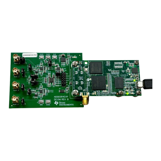
ADS8354EVM-PDK Evaluation Module
This user's guide describes the characteristics, operation, and use of the ADS8354 evaluation module (EVM)
performance demonstration kit (PDK). This kit is an evaluation platform for the ADS8354 device, which is a 16-
bit, dual-channel, simultaneous-sampling, 700-kSPS, differential analog input, successive approximation register
(SAR) analog-to-digital converter (ADC) that features an easy-to-use serial programming interface (SPI). The
ADS8354EVM-PDK eases evaluation with hardware, software, and computer connectivity through the universal
serial bus (USB) interface. This user's guide includes complete circuit descriptions, schematic diagrams, and a
bill of materials (BOM). Throughout this document, the terms evaluation board, evaluation module, and EVM are
synonymous with the ADS8354EVM-PDK.
SBAU407 – APRIL 2023
Submit Document Feedback
ABSTRACT
Copyright © 2023 Texas Instruments Incorporated
ADS8354EVM-PDK Evaluation Module
1
Advertisement
Table of Contents

Related Manuals for Texas Instruments ADS8354EVM-PDK


Summary of Contents for Texas Instruments ADS8354EVM-PDK
- Page 1 (SAR) analog-to-digital converter (ADC) that features an easy-to-use serial programming interface (SPI). The ADS8354EVM-PDK eases evaluation with hardware, software, and computer connectivity through the universal serial bus (USB) interface. This user's guide includes complete circuit descriptions, schematic diagrams, and a bill of materials (BOM).
-
Page 2: Table Of Contents
Prompts......................10 Figure 5-3. Device Driver Installation Wizard Prompts......................Figure 5-4. LabVIEW Run-Time Engine Installation........................Figure 5-5. ADS8354EVM-PDK Installation Final Step......................Figure 6-1. EVM-PDK Hardware Setup and LED Indicators..................... Figure 6-2. Launch the EVM GUI Software..........................Figure 6-3. EVM GUI Global Input Parameters......................... -
Page 3: Overview
Texas Instruments integrated circuits used in the assembly of the ADS8354EVM-PDK. This user's guide is available from the TI web site under literature number SBAU407. Any letter appended to the literature number corresponds to the document revision that is current at the time of the writing of this document. -
Page 4: Analog Interface
Analog inputs provided at the SMA for ADC B AINP_B AINM_B, JP1[1] and JP4[1] Alternate location to provide the analog inputs for ADC B AINP_B ADS8354EVM-PDK Evaluation Module SBAU407 – APRIL 2023 Submit Document Feedback Copyright © 2023 Texas Instruments Incorporated... -
Page 5: Adc Input Signal Driver
SINAD greater than 88 dB and a THD less than –97 dB for a 2-kHz sine-wave input at full throughput of the ADS8354 of 700 kSPS. Figure 2-1. ADS8354EVM Analog Input Path SBAU407 – APRIL 2023 ADS8354EVM-PDK Evaluation Module Submit Document Feedback Copyright © 2023 Texas Instruments Incorporated... -
Page 6: Figure 2-2. Ads8354Evm Common-Mode Voltage Buffer
REF_SEL bit in the CFG register to 0b (external reference) and install jumpers on JP7 and JP8. to REFIO_A on ADS8354 to REFIO_B on ADS8354 Figure 2-2. ADS8354EVM Common-Mode Voltage Buffer Circuit ADS8354EVM-PDK Evaluation Module SBAU407 – APRIL 2023 Submit Document Feedback Copyright © 2023 Texas Instruments Incorporated... -
Page 7: Digital Interfaces
C interface. The electrically erasable programmable read-only memory (EEPROM) comes preprogrammed with the information required to configure and initialize the ADS8354EVM-PDK platform. When the hardware is initialized, the EEPROM is no longer used. 3.1 SPI for the ADC Digital I/O... -
Page 8: Power Supplies
JP7 and JP8 jumpers. When using an external reference, the ADS8354 internal voltage reference must be disabled and the device must be programmed to accept the external reference voltage on the REFIO_x pins. ADS8354EVM-PDK Evaluation Module SBAU407 – APRIL 2023 Submit Document Feedback Copyright © 2023 Texas Instruments Incorporated... -
Page 9: Ads8354Evm-Pdk Initial Setup
This section explains the initial hardware and software setup procedure that must be completed for proper operation of the ADS8354EVM-PDK. 5.1 Default Jumper Settings Figure 5-1 shows the silkscreen plot, which details the jumper locations for the ADS8354EVM-PDK. Figure 5-1. ADS8354EVM-PDK Jumper Locations Table 5-1 lists the functionality and default configuration of each jumper. -
Page 10: Evm Graphical User Interface Software Installation
2. Accept the license agreements (Figure 5-2) and follow the on-screen instructions to complete the installation. Figure 5-2. ADS835xEVM Software Installation Prompts ADS8354EVM-PDK Evaluation Module SBAU407 – APRIL 2023 Submit Document Feedback Copyright © 2023 Texas Instruments Incorporated... -
Page 11: Figure 5-3. Device Driver Installation Wizard Prompts
A notice may appear on the screen stating that Windows cannot verify the publisher of this driver software. Select the Install this driver software anyway option. SBAU407 – APRIL 2023 ADS8354EVM-PDK Evaluation Module Submit Document Feedback Copyright © 2023 Texas Instruments Incorporated... -
Page 12: Figure 5-4. Labview Run-Time Engine Installation
Figure 5-4. LabVIEW Run-Time Engine Installation 4. Check the Create Desktop Shortcut box, as Figure 5-5 shows, after these installations. Figure 5-5. ADS8354EVM-PDK Installation Final Step ADS8354EVM-PDK Evaluation Module SBAU407 – APRIL 2023 Submit Document Feedback Copyright © 2023 Texas Instruments Incorporated... -
Page 13: Ads8354Evm-Pdk Operation
3. Launch the device EVM GUI software from the installed path, as Figure 6-2 shows, or by using the desktop shortcut created during installation. Figure 6-2. Launch the EVM GUI Software SBAU407 – APRIL 2023 ADS8354EVM-PDK Evaluation Module Submit Document Feedback Copyright © 2023 Texas Instruments Incorporated... -
Page 14: Evm Gui Global Settings For Adc Control
GUI (and the default values), through which the various functions of the ADS8354EVM-PDK can be exercised. These settings are global and persist across the GUI tools listed in the top left pane (or from one page to another). -
Page 15: Time Domain Display Tool
Figure 6-4, the user can trigger a data capture of the selected number of samples from the ADS8354EVM-PDK. The sample indices are on the x-axis, and two y-axes show the corresponding output codes and the equivalent analog voltages based on the specified reference voltage. Switching pages to any of the analysis tools described in the subsequent sections triggers calculations to be performed on the same set of data. -
Page 16: Spectral Analysis Tool
Signal frequency 2 kHz External source type Fully differential External source common-mode Minimum SNR 90 dB Minimum THD –115 dB Figure 6-5. Spectral Analysis Tool ADS8354EVM-PDK Evaluation Module SBAU407 – APRIL 2023 Submit Document Feedback Copyright © 2023 Texas Instruments Incorporated... -
Page 17: Histogram Analysis Tool
EVM configured by remove jumpers from pin 1 and 2 of jumper JP5 and JP6, shorting pin [1-2] of JP1, JP2, JP3, and JP4 using 100-mil jumpers. Figure 6-6. Histogram Analysis Tool SBAU407 – APRIL 2023 ADS8354EVM-PDK Evaluation Module Submit Document Feedback Copyright © 2023 Texas Instruments Incorporated... -
Page 18: Bill Of Materials, Printed-Circuit Board Layout, And Schematics
RC0603FR-0713RL R19, R20, R21, R22 YAGEO RES, 13.0, 1%, 0.1 W, 0603 ERJ-3GEY0R00V R23, R41 Panasonic RES, 0, 5%, 0.1 W, 0603 Electronic Components ADS8354EVM-PDK Evaluation Module SBAU407 – APRIL 2023 Submit Document Feedback Copyright © 2023 Texas Instruments Incorporated... - Page 19 Low Noise Negative Bias Generator, 8-pin Mini SOIC, Pb-Free BR24G32FVT-3AGE2 Rohm I2C BUS EEPROM (2-Wire), TSSOP-B8 Semiconductor TPS7A4701QRGWRQ1 Texas Instruments Automotive 35V, 1A, 4.2?VRMS, RF Low-Dropout (LDO) Voltage Regulator, RGW0020A (VQFN-20) SBAU407 – APRIL 2023 ADS8354EVM-PDK Evaluation Module Submit Document Feedback Copyright © 2023 Texas Instruments Incorporated...
-
Page 20: Pcb Layout
Figure 7-2. ADS8354EVM PCB Layer 2: GND Plane Figure 7-4. ADS8354EVM PCB Layer 4: Bottom Figure 7-3. ADS8354EVM PCB Layer 3: Power Layer Plane ADS8354EVM-PDK Evaluation Module SBAU407 – APRIL 2023 Submit Document Feedback Copyright © 2023 Texas Instruments Incorporated... -
Page 21: Schematics
Bill of Materials, Printed-Circuit Board Layout, and Schematics 7.3 Schematics Figure 7-5 through Figure 7-7 illustrate the schematics for the ADS8354EVM-PDK. Positive Supply EVM_REG_5V5 LDO_IN_5V5 AVDD SENSE/FB 10uF 1µF EEPROM 6P4V2 6P4V1 3P2V 47uF 1P6V EVM_ID_PWR EVM_ID_PWR 0P8V EVM_ID_PWR... -
Page 22: Figure 7-6. Schematic Diagram (Page 2): Analog Inputs, Adc Main, External Reference, Phi Connector
AVDD 15.0 13.0 0.1uF AVSS 10pF AINM_B 100pF 1.50k 1.50k Figure 7-6. Schematic Diagram (Page 2): Analog Inputs, ADC Main, External Reference, PHI Connector ADS8354EVM-PDK Evaluation Module SBAU407 – APRIL 2023 Submit Document Feedback Copyright © 2023 Texas Instruments Incorporated... -
Page 23: Figure 7-7. Schematic Diagram (Page 3): Hardware Components
These assemblies must be clean and free from flux and all contaminants. Use of no clean flux is not acceptable. Assembly Note These assemblies must comply with workmanship standards IPC-A-610 Class 2, unless otherwise specified. Figure 7-7. Schematic Diagram (Page 3): Hardware Components SBAU407 – APRIL 2023 ADS8354EVM-PDK Evaluation Module Submit Document Feedback Copyright © 2023 Texas Instruments Incorporated... - Page 24 STANDARD TERMS FOR EVALUATION MODULES Delivery: TI delivers TI evaluation boards, kits, or modules, including any accompanying demonstration software, components, and/or documentation which may be provided together or separately (collectively, an “EVM” or “EVMs”) to the User (“User”) in accordance with the terms set forth herein.
- Page 25 www.ti.com Regulatory Notices: 3.1 United States 3.1.1 Notice applicable to EVMs not FCC-Approved: FCC NOTICE: This kit is designed to allow product developers to evaluate electronic components, circuitry, or software associated with the kit to determine whether to incorporate such items in a finished product and software developers to write software applications for use with the end product.
- Page 26 www.ti.com Concernant les EVMs avec antennes détachables Conformément à la réglementation d'Industrie Canada, le présent émetteur radio peut fonctionner avec une antenne d'un type et d'un gain maximal (ou inférieur) approuvé pour l'émetteur par Industrie Canada. Dans le but de réduire les risques de brouillage radioélectrique à...
- Page 27 www.ti.com EVM Use Restrictions and Warnings: 4.1 EVMS ARE NOT FOR USE IN FUNCTIONAL SAFETY AND/OR SAFETY CRITICAL EVALUATIONS, INCLUDING BUT NOT LIMITED TO EVALUATIONS OF LIFE SUPPORT APPLICATIONS. 4.2 User must read and apply the user guide and other available documentation provided by TI regarding the EVM prior to handling or using the EVM, including without limitation any warning or restriction notices.
- Page 28 Notwithstanding the foregoing, any judgment may be enforced in any United States or foreign court, and TI may seek injunctive relief in any United States or foreign court. Mailing Address: Texas Instruments, Post Office Box 655303, Dallas, Texas 75265 Copyright © 2023, Texas Instruments Incorporated...
- Page 29 TI products. TI’s provision of these resources does not expand or otherwise alter TI’s applicable warranties or warranty disclaimers for TI products. TI objects to and rejects any additional or different terms you may have proposed. IMPORTANT NOTICE Mailing Address: Texas Instruments, Post Office Box 655303, Dallas, Texas 75265 Copyright © 2023, Texas Instruments Incorporated...
Need help?
Do you have a question about the ADS8354EVM-PDK and is the answer not in the manual?
Questions and answers