Table of Contents
Advertisement
Quick Links
Advertisement
Table of Contents

Subscribe to Our Youtube Channel
Related Manuals for Texas Instruments ADS7861 EVM


Summary of Contents for Texas Instruments ADS7861 EVM
- Page 1 ADS7861/8361 EVM User’s Guide October 2002 Data Acquisition Products SLAU094...
- Page 2 IMPORTANT NOTICE Texas Instruments Incorporated and its subsidiaries (TI) reserve the right to make corrections, modifications, enhancements, improvements, and other changes to its products and services at any time and to discontinue any product or service without notice. Customers should obtain the latest relevant information before placing orders and should verify that such information is current and complete.
- Page 3 EVM IMPORTANT NOTICE Texas Instruments (TI) provides the enclosed product(s) under the following conditions: This evaluation kit being sold by TI is intended for use for ENGINEERING DEVELOPMENT OR EVALUATION PURPOSES ONLY and is not considered by TI to be fit for commercial use. As such, the goods being provided may not be complete in terms of required design-, marketing-, and/or manufacturing-related protective considerations, including product safety measures typically found in the end product incorporating the goods.
- Page 4 EVM schematic located in the EVM User’s Guide. When placing measurement probes near these devices during operation, please be aware that these devices may be very warm to the touch. Mailing Address: Texas Instruments Post Office Box 655303 Dallas, Texas 75265 Copyright 2002, Texas Instruments Incorporated...
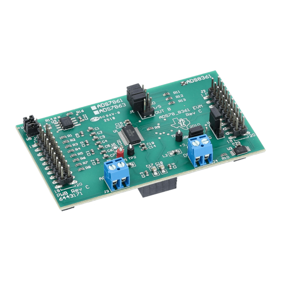
- Page 5 Related Documentation From Texas Instruments Preface Read This First About This Manual This users guide describes the characteristics, operation, and use of the ADS7861/8361 EVM – 12-/16-bit dual, 500-KSPS, 2+2 channel, serial analog- to-digital converter evaluation module. A complete circuit description as well as a schematic diagram and bill of materials are included.
- Page 6 Trademarks TI Logo is a trademark of Texas Instruments Incorporated.
-
Page 7: Table Of Contents
Contents Contents EVM Overview ..............Features . - Page 8 Contents...
-
Page 9: Evm Overview
Chapter 1 EVM Overview The ADS7861 and ADS8361 are high-speed, low-power, 12-bit and 16-bit A/D converters that operate from independent 5-V AV and 5-V D (2.7-V to 3.6-V DV for ADS8361) supplies. The four fully differential analog inputs are divided into two pairs (A and B). The ADS7861 and ADS8361 accept an analog input voltage in the range of –VREF to +VREF (5 V ), centered on the internal 2.5-V reference. -
Page 10: Features
Features 1.1 Features Full-featured evaluation board for the ADS7861 and ADS8361, dual, 500-kSPS, 12-bit/16-bit, serial output, 2+2 analog input, simultaneous sampling analog-to-digital converter Analog inputs can be configured as single-ended or differential Built-in reference High-speed serial interface... -
Page 11: Analog Interface
Chapter 2 Analog Interface For maximum flexibility, the ADS7861/8361 EVM is designed for easy interfacing multiple analog sources. Samtec part numbers SSW–110–22–F–D–VS–K and TSM–110–01–T–DV–P provide a convenient ten-pin dual row header/socket combination at J1. This header/socket provides access to the analog input pins of the ADC. Consult Samtec at www.samtec.com or call 1–800–SAMTEC–9 for a variety of mating connector options. -
Page 13: Digital Interface
Chapter 3 Digital Interface The ADS7861/8361 EVM is designed for easy interfacing to multiple control platforms. Samtec part numbers SSW–110–22–F–D–VS–K TSM–110–01–T–DV–P provide a convenient ten-pin dual row header/socket combination at J2. This header/socket provides access to the digital control and serial data pins of the ADS7861/8361. Consult Samtec at www.sam- tec.com or 1–800–SAMTEC–9 for a variety of mating connector options. -
Page 14: Additional Control Options
Additional Control Options 3.1 Additional Control Options The following table shows the pin-out of header J5. This dual row, four-position header provides additional control functionality to the ADS7861/8361 EVM. Signals A0, M0, and M1 are configured with pull-up resistors by default. The jumper shunts supplied with the EVM can be used to set these signals to logic low. -
Page 15: Power Supplies
Chapter 4 Power Supplies The ADS7861 EVM board requires 5 V dc for both the analog and digital sections of the ADC. While filters are provided for all power supply inputs, optimal performance of the EVM requires a clean, well-regulated power source. -
Page 16: Reference Voltage
Reference Voltage 4.1 Reference Voltage The ADS7861/8361 can be configured to use its internal reference, or external reference source through jumper W1 (see schematic for details). If an external reference is desired, the shunt jumper on W1 should cover pins 2 and 3. The external reference is supplied through header/socket J1 pin 20 (J1.20). -
Page 17: Evm Operation
Chapter 5 EVM Operation Apply a current limited (150 mA max) 5-V dc source to J3 and J4 prior to connecting the analog input signals and digital control signals. The analog input source can be applied directly to header/socket J1 (top or bottom side) or through optional amplifier and signal conditioning modules. -
Page 19: Bill Of Materials And Evm Schematic
9C08052A1002JLHFT 0-Ω, 0805, 0.1-W resistor Yageo America 9C08052A0R00JLHFT TP1 TP2 TP3 Red test point loop Keystone 5000 ADS7861 or ADS8361 ADC Texas Instruments ADS7861E or ADS8361I 3 Pin, 2-mm header Samtec TMM–103–01–G–S W2, W3 3 Pin header Samtec TSW–103–07–L–S Bill of Materials and EVM Schematic... - Page 20 Revision History ECN Number Approved 49.9 100pF CLOCK 11 12 100pF 13 14 15 16 49.9 17 18 Data A 19 20 49.9 100pF BUSY 100pF CONVST 49.9 DVdd 49.9 100pF 11 12 REFout 13 14 15 16 100pF 17 18 REFin 19 20 Data B...
Need help?
Do you have a question about the ADS7861 EVM and is the answer not in the manual?
Questions and answers