Table of Contents
Advertisement
Quick Links
This user's guide describes the operation and use of the ADS8688 evaluation module (EVM). The
ADS8688
is an 8-channel integrated data acquisition system based on a 16-bit successive approximation
(SAR) analog-to-digital converter (ADC). Each input channel on the device can support true bipolar input
ranges of ±10.24 V, ±5.12 V, and ±2.56 V, as well as unipolar input ranges of 0 V to 10.24 V and 0 V to
5.12 V. The input range selection is done by software programming the device internal registers and is
independent for each channel. The device offers a 1-MΩ, constant resistive input impedance irrespective
of the selected input range This user's guide covers circuit description, schematic diagram, and bill of
materials for the ADS8688EVM circuit board.
Table 1
lists the related documents that are available through the Texas Instruments web site at
www.ti.com.
SBAU230A – August 2014 – Revised December 2014
Submit Documentation Feedback
ADS8688EVM-PDK Evaluation Module
ADS8688EVM-PDK
Table 1. Related Documentation
Device
ADS8688
OPA376
OPA2209
OPA320
REG71055
TPA7A4901
TPS54060
TPS7A3001
Copyright © 2014, Texas Instruments Incorporated
SBAU230A – August 2014 – Revised December 2014
Literature Number
SBAS582
SBOS406
SBOS426
SBOS513
SBAS221
SBVS121
SLVS919
SBVS125
ADS8688EVM-PDK Evaluation Module
User's Guide
1
Advertisement
Table of Contents

Related Manuals for Texas Instruments ADS8688EVM-PDK


Summary of Contents for Texas Instruments ADS8688EVM-PDK
- Page 1 This user's guide covers circuit description, schematic diagram, and bill of materials for the ADS8688EVM circuit board. Table 1 lists the related documents that are available through the Texas Instruments web site at www.ti.com. Table 1. Related Documentation...
-
Page 2: Table Of Contents
Data Capture in Auto Mode with Single Graph View ..............Data Capture in Auto Mode with Multi Graph View ....................Saving the Captured Data ADS8688EVM-PDK Evaluation Module SBAU230A – August 2014 – Revised December 2014 Submit Documentation Feedback Copyright © 2014, Texas Instruments Incorporated... - Page 3 Jumper Settings for Generating HVDD and HVSS from External High-Voltage Supplies ....................Power-Supply Connections ..................... Default Jumper Configuration ..................ADS8688EVM Bill of Materials SBAU230A – August 2014 – Revised December 2014 ADS8688EVM-PDK Evaluation Module Submit Documentation Feedback Copyright © 2014, Texas Instruments Incorporated...
-
Page 4: Ads8688Evm-Pdk Overview
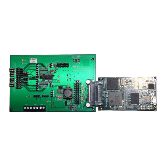
ADS8688EVM-PDK Overview The ADS8688EVM-PDK is a platform for evaluating the ADS8688 device. The ADS8688EVM-PDK consists of an ADS8688EVM board and a Simple Capture card. The Simple Capture card is an FPGA- based controller card that functions as an serial peripheral interface (SPI™) host and transfers data to the ADS8688EVM graphical user interface (GUI) via a USB interface. -
Page 5: Evm Analog Interface
357 AIN_xP 357 10 nF AIN_xGND Figure 2. ADS8688EVM Analog Input Connections for Channels AIN4, AIN5, AIN6, and AIN7 SBAU230A – August 2014 – Revised December 2014 ADS8688EVM-PDK Evaluation Module Submit Documentation Feedback Copyright © 2014, Texas Instruments Incorporated... -
Page 6: Connecting Negative Inputs To Ground
A3– Closed Open A4– Closed Open A5– Closed Open A6– Closed Open A7– Closed Open AUX– Always connected to GND ADS8688EVM-PDK Evaluation Module SBAU230A – August 2014 – Revised December 2014 Submit Documentation Feedback Copyright © 2014, Texas Instruments Incorporated... -
Page 7: Using Onboard, Second-Order, Butterworth, Low-Pass Filters
Closed Open Table 7. External Reference Connections Number Signal Description J5.1 REFIN Input for external reference J5.2 Analog ground connection SBAU230A – August 2014 – Revised December 2014 ADS8688EVM-PDK Evaluation Module Submit Documentation Feedback Copyright © 2014, Texas Instruments Incorporated... -
Page 8: Digital Interface
The ADS8688EVM has an SD card that contains the software files for the Simple Capture card. The contents of the SD card must not be deleted or altered. ADS8688EVM-PDK Evaluation Module SBAU230A – August 2014 – Revised December 2014 Submit Documentation Feedback Copyright © 2014, Texas Instruments Incorporated... -
Page 9: Power Supplies
Required only for generating HVDD and HVSS from external External HVSS EXT_HVSS –16 V to –25 V J18.1 high-voltage supplies — J18.2 — SBAU230A – August 2014 – Revised December 2014 ADS8688EVM-PDK Evaluation Module Submit Documentation Feedback Copyright © 2014, Texas Instruments Incorporated... -
Page 10: Power-Supply Connections Diagram
REG71055 charge pump and the TPS7A4901 linear regulator. The DVDD digital supply for the ADC is derived from a 3.3-V supply from the Simple Capture card. ADS8688EVM-PDK Evaluation Module SBAU230A – August 2014 – Revised December 2014 Submit Documentation Feedback Copyright © 2014, Texas Instruments Incorporated... -
Page 11: Ads8688Evm-Pdk Initial Setup
ADS8688EVM-PDK Initial Setup www.ti.com ADS8688EVM-PDK Initial Setup This section presents the steps required to setup the ADS8688EVM-PDK kit before operation. Default Jumper Settings Figure 4 details the default jumper settings. Table 12 provides the configuration for these jumpers. Figure 4. ADS8688EVM Default Jumper Settings SBAU230A –... -
Page 12: Software Installation
1. Verify the microSD memory cards are installed on the Simple Capture card and the ADS8688EVM board. 2. Verify jumpers are in the factory-default position and properly connect the hardware. 3. Install the ADS8688EVM-PDK software. 4. Complete the Simple Capture card device driver installation. Each task is described in the following subsections. -
Page 13: Bottom View Of The Simple Capture Card With The Microsd Memory Card Installed
5.2.1 Verify the microSD Memory Card is Installed on the Simple Capture card The ADS8688EVM-PDK includes microSD memory cards that contain the EVM software and Simple Capture card firmware required for the EVM operation. NOTE: Ensure the microSD memory cards that contain the software are installed in the microSD socket on the back of the Simple Capture card and on the back of ADS8688EVM board. -
Page 14: Connecting The Ads8688Evm Board To The Simple Capture Card
Verify Jumpers are in the Factory-Default Position and Connect the Hardware The ADS8688EVM-PDK includes both the ADS8688EVM and the Simple Capture card; however, the devices are shipped unconnected. Follow these steps to verify that the ADS8688EVM-PDK kit is configured and connected properly. -
Page 15: Destination Directory Screen
Simple Capture card device driver components. 4. After the installer begins, a welcome screen displays. Click Next to continue. 5. A prompt appears with the destination directory; select the default directory under: ...\Program Files(x86)\Texas Instruments\ADS8684_8 EVM GUI\ as shown in Figure 9 Figure Figure 9. -
Page 16: Start Installation Screen
The drivers contained within the installers are safe for installation to your system. Figure 13. Windows 7 Driver Installation Warning ADS8688EVM-PDK Evaluation Module SBAU230A – August 2014 – Revised December 2014 Submit Documentation Feedback Copyright © 2014, Texas Instruments Incorporated... -
Page 17: Installation Wizard Screen
2. A computer restart may be required to finish the software installation. If prompted, restart the computer to complete the installation. Figure 14. Installation Wizard Screen Figure 15. Simple Capture Card Device Driver Completion SBAU230A – August 2014 – Revised December 2014 ADS8688EVM-PDK Evaluation Module Submit Documentation Feedback Copyright © 2014, Texas Instruments Incorporated... -
Page 18: Ads8688Evm-Pdk Kit Operation
ADS8688EVM-PDK Kit Operation www.ti.com ADS8688EVM-PDK Kit Operation This section describes how to use the ADS8688EVM-PDK and ADS8688EVM GUI to configure the EVM and acquire data. About the Simple Capture Card The Simple Capture card provides the USB interface between the computer and the ADS8688EVM. The controller board is designed around the AM335x processor, a USB 2.0, high-speed capability, 32-bit, ARM... -
Page 19: Configuring The Ads8688Evm
Figure Figure 18 displays the window for selecting the input voltage ranges. SBAU230A – August 2014 – Revised December 2014 ADS8688EVM-PDK Evaluation Module Submit Documentation Feedback Copyright © 2014, Texas Instruments Incorporated... -
Page 20: System Block Diagram View
ADS8688EVM-PDK Kit Operation www.ti.com Figure 17. System Block Diagram View Figure 18. Selecting the Input Range for the Channels ADS8688EVM-PDK Evaluation Module SBAU230A – August 2014 – Revised December 2014 Submit Documentation Feedback Copyright © 2014, Texas Instruments Incorporated... -
Page 21: Register Map View
For details on the ADS8688 program registers, refer to the program register map in the ADS8688 data sheet. Figure 19 shows the register map view. Figure 19. Register Map View SBAU230A – August 2014 – Revised December 2014 ADS8688EVM-PDK Evaluation Module Submit Documentation Feedback Copyright © 2014, Texas Instruments Incorporated... -
Page 22: Capturing The Data
The Section 6.4.1 Section 6.4.2 sections provide the details for manual and auto mode, respectively. ADS8688EVM-PDK Evaluation Module SBAU230A – August 2014 – Revised December 2014 Submit Documentation Feedback Copyright © 2014, Texas Instruments Incorporated... -
Page 23: Manual Mode Data Capture
2. The data captured are displayed in a graph in the GUI window. Figure 21. Manual Mode Data Capture SBAU230A – August 2014 – Revised December 2014 ADS8688EVM-PDK Evaluation Module Submit Documentation Feedback Copyright © 2014, Texas Instruments Incorporated... -
Page 24: Data Capture In Auto Mode With Single Graph View
Figure 23 illustrate the data captured in auto mode. Figure 22. Data Capture in Auto Mode with Single Graph View ADS8688EVM-PDK Evaluation Module SBAU230A – August 2014 – Revised December 2014 Submit Documentation Feedback Copyright © 2014, Texas Instruments Incorporated... -
Page 25: Data Capture In Auto Mode With Multi Graph View
ADS8688EVM-PDK Kit Operation www.ti.com Figure 23. Data Capture in Auto Mode with Multi Graph View SBAU230A – August 2014 – Revised December 2014 ADS8688EVM-PDK Evaluation Module Submit Documentation Feedback Copyright © 2014, Texas Instruments Incorporated... -
Page 26: Analyzing The Data
ADS8688EVM in auto or manual mode. Data can be analyzed with the Selected Analysis from the drop- down menu in the ADC capture settings. ADS8688EVM-PDK Evaluation Module SBAU230A – August 2014 – Revised December 2014 Submit Documentation Feedback Copyright © 2014, Texas Instruments Incorporated... - Page 27 The FFT calculated parameters are shown on the bottom side of the graph. SBAU230A – August 2014 – Revised December 2014 ADS8688EVM-PDK Evaluation Module Submit Documentation Feedback Copyright © 2014, Texas Instruments Incorporated...
-
Page 28: Phase Compensation
(TIDU427). The phase compensation analysis page can be activated from the Smart App menu. Figure 27 displays the phase compensation analysis page. ADS8688EVM-PDK Evaluation Module SBAU230A – August 2014 – Revised December 2014 Submit Documentation Feedback Copyright © 2014, Texas Instruments Incorporated... - Page 29 ADS8688EVM-PDK Kit Operation www.ti.com Figure 27. Phase Compensation Analysis SBAU230A – August 2014 – Revised December 2014 ADS8688EVM-PDK Evaluation Module Submit Documentation Feedback Copyright © 2014, Texas Instruments Incorporated...
-
Page 30: Ads8688Evm Gui Simulation Mode
ADS8688EVM board and only displays the results for one set of captured data stored in the computer. Figure 28 shows the ADS8688EVM GUI running in simulation mode. Figure 28. Simulation Mode ADS8688EVM-PDK Evaluation Module SBAU230A – August 2014 – Revised December 2014 Submit Documentation Feedback Copyright © 2014, Texas Instruments Incorporated... -
Page 31: Bill Of Materials, Schematics, And Layout
B260A-13-F D3, D5 Diode, Zener, 5.6V, 500mW, SOD-123 ON Semiconductor MMSZ4690T1G D6, D8 Diode, Zener, 27V, 500mW, SOD-123 Vishay-Semiconductor MMSZ4711-V SBAU230A – August 2014 – Revised December 2014 ADS8688EVM-PDK Evaluation Module Submit Documentation Feedback Copyright © 2014, Texas Instruments Incorporated... - Page 32 RES, 44.2k ohm, 1%, 0.063W, 0402 Vishay-Dale CRCW040244K2FKED RES, 412k ohm, 1%, 0.063W, 0402 Vishay-Dale CRCW0402412KFKED RES, 20.5k ohm, 1%, 0.063W, 0402 Vishay-Dale CRCW040220K5FKED ADS8688EVM-PDK Evaluation Module SBAU230A – August 2014 – Revised December 2014 Submit Documentation Feedback Copyright © 2014, Texas Instruments Incorporated...
- Page 33 V Input and 0.8 to 58 V Output, -40 to 150 degC, 10-Pin Texas Instruments TPS54060DGQ MSOP-PowerPAD (DGQ), Green (RoHS & no Sb/Br) SBAU230A – August 2014 – Revised December 2014 ADS8688EVM-PDK Evaluation Module Submit Documentation Feedback Copyright © 2014, Texas Instruments Incorporated...
-
Page 34: Board Layouts
NOTE: Board layouts are not to scale. These figures are intended to show how the board is laid out; these figures are not intended to be used for manufacturing ADS8688EVM PCBs. Figure 29. ADS8688EVM PCB: Top Layer (L1) ADS8688EVM-PDK Evaluation Module SBAU230A – August 2014 – Revised December 2014 Submit Documentation Feedback Copyright © 2014, Texas Instruments Incorporated... - Page 35 Bill of Materials, Schematics, and Layout www.ti.com Figure 30. ADS8688EVM PCB: Ground Layer (L2) SBAU230A – August 2014 – Revised December 2014 ADS8688EVM-PDK Evaluation Module Submit Documentation Feedback Copyright © 2014, Texas Instruments Incorporated...
- Page 36 Bill of Materials, Schematics, and Layout www.ti.com Figure 31. ADS8688EVM PCB: Analog Power Layer (L3) ADS8688EVM-PDK Evaluation Module SBAU230A – August 2014 – Revised December 2014 Submit Documentation Feedback Copyright © 2014, Texas Instruments Incorporated...
- Page 37 Bill of Materials, Schematics, and Layout www.ti.com Figure 32. ADS8688EVM PCB: Digital Power Layer (L4) SBAU230A – August 2014 – Revised December 2014 ADS8688EVM-PDK Evaluation Module Submit Documentation Feedback Copyright © 2014, Texas Instruments Incorporated...
- Page 38 Bill of Materials, Schematics, and Layout www.ti.com Figure 33. ADS8688EVM PCB: Ground Layer (L5) ADS8688EVM-PDK Evaluation Module SBAU230A – August 2014 – Revised December 2014 Submit Documentation Feedback Copyright © 2014, Texas Instruments Incorporated...
- Page 39 Bill of Materials, Schematics, and Layout www.ti.com Figure 34. ADS8688EVM PCB: Bottom Layer (L6) SBAU230A – August 2014 – Revised December 2014 ADS8688EVM-PDK Evaluation Module Submit Documentation Feedback Copyright © 2014, Texas Instruments Incorporated...
- Page 40 3/13/2014 SCHEMATIC, EVM, This allows the connection of two nets, Texas Instruments and/or its licensors do not warrant the accuracy or completeness of this ENGINEER: DATE: without compiler errors or a physical component. specification or any information contained therein. Texas Instruments and/or its licensors do not...
- Page 41 AT24C02B 0.1µF R104 49.9 R103 R102 SCLK R107 SCLK 10µF EVMSDCLK CLOCK R100 EVMSDDATA0 DATA0 EVMSDDATA1 DATA1 Shell 3V3_SDCC 5V_SDCC 502570-0893 EVM_ID_SDA EVM_ID_SCL REFSEL 49.9 49.9 49.9 RST/PD DAISY 49.9 ERF8-025-01-L-D-RA-L-TR © Texas Instruments 2014 http://www.ti.com SCALE SHEET 6573934 SIZE...
- Page 42 Changed all instances of “SDCC Controller board” to “Simple Capture card” throughout this document NOTE: Page numbers for previous revisions may differ from page numbers in the current version. Revision History SBAU230A – August 2014 – Revised December 2014 Submit Documentation Feedback Copyright © 2014, Texas Instruments Incorporated...
- Page 43 STANDARD TERMS AND CONDITIONS FOR EVALUATION MODULES Delivery: TI delivers TI evaluation boards, kits, or modules, including any accompanying demonstration software, components, or documentation (collectively, an “EVM” or “EVMs”) to the User (“User”) in accordance with the terms and conditions set forth herein. Acceptance of the EVM is expressly subject to the following terms and conditions.
- Page 44 FCC Interference Statement for Class B EVM devices NOTE: This equipment has been tested and found to comply with the limits for a Class B digital device, pursuant to part 15 of the FCC Rules. These limits are designed to provide reasonable protection against harmful interference in a residential installation.
- Page 45 【無線電波を送信する製品の開発キットをお使いになる際の注意事項】 本開発キットは技術基準適合証明を受けておりません。 本製品のご使用に際しては、電波法遵守のため、以下のいずれかの措置を取っていただく必要がありますのでご注意ください。 1. 電波法施行規則第6条第1項第1号に基づく平成18年3月28日総務省告示第173号で定められた電波暗室等の試験設備でご使用 いただく。 2. 実験局の免許を取得後ご使用いただく。 3. 技術基準適合証明を取得後ご使用いただく。 なお、本製品は、上記の「ご使用にあたっての注意」を譲渡先、移転先に通知しない限り、譲渡、移転できないものとします。 上記を遵守頂けない場合は、電波法の罰則が適用される可能性があることをご留意ください。 日本テキサス・インスツルメンツ株式会社 東京都新宿区西新宿6丁目24番1号 西新宿三井ビル 3.3.3 Notice for EVMs for Power Line Communication: Please see http://www.tij.co.jp/lsds/ti_ja/general/eStore/notice_02.page 電力線搬送波通信についての開発キットをお使いになる際の注意事項については、次のところをご覧くださ い。http://www.tij.co.jp/lsds/ti_ja/general/eStore/notice_02.page SPACER EVM Use Restrictions and Warnings: 4.1 EVMS ARE NOT FOR USE IN FUNCTIONAL SAFETY AND/OR SAFETY CRITICAL EVALUATIONS, INCLUDING BUT NOT LIMITED TO EVALUATIONS OF LIFE SUPPORT APPLICATIONS.
- Page 46 Notwithstanding the foregoing, any judgment may be enforced in any United States or foreign court, and TI may seek injunctive relief in any United States or foreign court. Mailing Address: Texas Instruments, Post Office Box 655303, Dallas, Texas 75265 Copyright © 2014, Texas Instruments Incorporated...
- Page 47 IMPORTANT NOTICE Texas Instruments Incorporated and its subsidiaries (TI) reserve the right to make corrections, enhancements, improvements and other changes to its semiconductor products and services per JESD46, latest issue, and to discontinue any product or service per JESD48, latest issue.
Need help?
Do you have a question about the ADS8688EVM-PDK and is the answer not in the manual?
Questions and answers