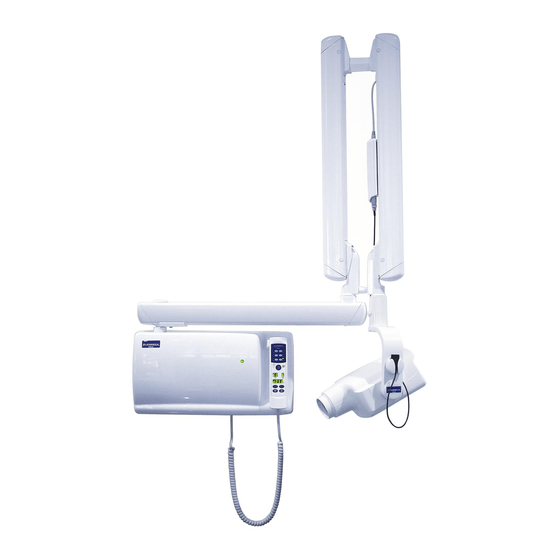
Planmeca Intra Quick Reference Manual
Hide thumbs
Also See for Intra:
- Installation manual (68 pages) ,
- User manual (64 pages) ,
- Technical manual (58 pages)
Table of Contents
Advertisement
Quick Links
Advertisement
Table of Contents

Summary of Contents for Planmeca Intra
- Page 1 Quick Reference Manual...
- Page 2 IEC364. Equipment is used according to the operating instructions Planmeca pursues a policy of continual product development. Although every effort is made to produce up-to-date product documentation this publication should not be regarded as an infallible guide to current specifications.
-
Page 3: Table Of Contents
TABLE OF CONTENTS INTRAORAL A. Install Intra Remote Phone Jack Wire Diagram ii. Wall Exposure Wire Diagram iii. Intra Remote Wire Diagrams iv. Planmeca Intra Parameter Card B. Troubleshooting iv. Factory Default Settings v. Invasive kV/mA Test vi. Error Codes vii. -
Page 4: Install
vi. Help/Error Codes vii. ProMax 2D Internal Wire Diagram viii. ProMax 3D Internal Wire Diagram C. Calibrating ProMax Calibration Block Procedures ii. ProMax DEC Calibration Procedures iii. Abridged Digital Pan/Ceph Calibration Manual PROONE A. Install Wall Exposure Wire Diagram ii. ProOne Dimensions B. - Page 5 Quick Reference Manual...
-
Page 6: Intra Remote Phone Jack Wire Diagram
Intra Phone Jack Wire Diagram +VCC and EXP are used for a remote exposure switch Intra Generator Board +12v – Wiring Guide +12v .– Black – Red – Green – Yellow Note: Blue and white terminals are not used. Back side of the wall plate... -
Page 7: Wall Exposure Wire Diagram
Optional remote exposure switch VCC – VCC EXP – EXPOUT ELMP – EXPIND EXPIND Set exposure terminal to ON EXPOUT Set buzzer to OFF (ON if desired) Quick Reference Manual... -
Page 8: Intra Remote Wire Diagrams
Quick Reference Manual... -
Page 9: Planmeca Intra Parameter Card
IMPORTANT !!! Planmeca Intra is factory pre-programmed for short cone and F-speed film (i.e. Kodak Insight film) To change the preset density settings (film type): The density setting will determine how dark the image will be. Changing the density setting is a quick way of adjusting all the pre-set buttons at once for a specific film in use. -
Page 10: Factory Default Settings
Factory Default Settings For the Planmeca Intra (3.06) Film Adult Time Child Time Bitewing 0.08 Bitewing 0.064 Endo 0.08 Endo 0.064 Upper Occlusal 0.08 Upper Occulsal 0.064 Lower Occlusal 0.08 Lower Occulsal 0.064 Upper Centrals 0.08 Upper Centrals 0.05 Lower Centrals 0.064... -
Page 11: Invasive Kv/Ma Test
Intra Invasive kV/mA Test NOTE: Time must be set above 0.200 seconds to be able to get a reading. On the tubehead pcb P1 connector, measure DC volts between pins 1&2 during exposure. The reading should be: kV x 0.04614 = Volts +/- 10% On the tubehead pcb P1 connector, measure DC volts between pins 3&4 during exposure. -
Page 12: Error Codes
Intra Error Codes ERROR CODE ERROR MESSAGE EXPLANATION Exposure key was released too early during the exposure. E.00 - check the control panel cable, telephone cable, and the arm cable. - replace the control panel or use another exposure switch. -
Page 13: Recalling Factory Presets
Tube head temperature sensor short circuit. E.50 - check feedback cable flip feedback cable over. - replace tubehead Tube head temperature sensor open circuit. E.51 - check arm cable, check feedback cable. flip feedback cable over - replace tubehead pcb, tubehead. (this order) Filament voltage feedback not in specified limits. -
Page 14: Planmeca Intra Internal Wire Diagram
Planmeca Intra Internal Wire Diagram Quick Reference Manual... -
Page 15: Proline
Proline Quick Reference Manual... -
Page 16: Setting The Time And Date
Setting Time and Date Proline XC: Press i Press Time and date adjustment Time (24hr clock) a. First is minutes, adjust up or down to proper minutes then press Next Adjusts second minute number then first minute number IE: if x:34, adjusts up or down for the 4, press Next and then up or down for the 3 then press Next b. -
Page 17: Proline Dimensions
Proline Dimensions Quick Reference Manual... -
Page 18: Cc/Ec Beam Alignment
CC/EC Beam Alignment 1. Hold CTL and CEPH key for 6 seconds. 2. Press CTL once let go, and then press the Collimator Selection key let go. 3. Press Exposure button to check beam. 4. If the beam is too left/right, use the mm +/- to move the beam. (Figure 4) NOTE: The beam will not move while exposing. -
Page 19: Proline Pcbs
Proline PCBs CC/EC Film CC/EC Digital XEC/XC Keyboard Processor Keyboard Processor Keyboard Processor 665070 10002568 10009419 (3.51KP/2.07GP or earlier) (Proline 5.x to 6.x) Generator Processor Generator Processor 665180 10009814 Power Generator Proline PSU PCB 662051 10009812 Low Voltage PCB Tube head 471023 Tube head 10010470 &... -
Page 20: Software Version/Compatibility
Software Version/Compatibility Generator Processor PCB 665069 665180 665181 10009814 Version –B6 Version –C or later Version –C or New EMC PCB or older “one small later 105-10-28 “one big software chip” “one small “one small software software software chip” chip” chip”...


Need help?
Do you have a question about the Intra and is the answer not in the manual?
Questions and answers