Julabo DYNEO DD Operating Manual
Circulator
Hide thumbs
Also See for DYNEO DD:
- Original operating manual (96 pages) ,
- Operating instructions manual (97 pages) ,
- Original operating manual (92 pages)

Related Manuals for Julabo DYNEO DD


Summary of Contents for Julabo DYNEO DD
- Page 1 Heating immersion circulators, heating circulators with open baths, refrigerated circulators Original operating manual 1.950.1300.en.V04 12/2022 1.888.610.7664 www.calcert.com sales@calcert.com...
- Page 2 Legal The content of this operating manual is protected by copyright. Information, including texts, images, and other contents may not be reproduced, distributed, transmitted, stored or otherwise used in any form without prior explicit written consent. Illustrations in this operating manual are for illustrative purposes and are not necessarily displayed to scale.
-
Page 3: Table Of Contents
Foreword ..................... 7 About this manual ................8 Original JULABO spare parts ............8 Accessories ..................8 Warnings ..................9 Symbols used ................10 Intended use ..................11 Safety ....................12 Safety instructions ................. 12 Safety symbols ................14 Safety function ................14 Product description................ - Page 4 5.9.5 Programmer menu ..............28 5.9.6 Menu Connect unit ..............28 5.9.7 Service menu ................29 5.9.8 Install unit menu ............... 29 5.10 Technical data ................30 5.10.1 Material of parts that come into contact with the medium ..32 5.10.2 Technical data for refrigerated circulators ........
- Page 5 Operation ................... 57 Switch on the unit ................57 Switch off the unit ................57 Start temperature control application ..........57 Basic settings ................58 8.4.1 Set language ................58 8.4.2 Set date and time ..............58 8.4.3 Activate autostart function ............59 8.4.4 Set physical units ..............
- Page 6 8.9.1 Configure signal outputs of the REG/EPROG plug ....72 8.10 Activating stand-by input ............... 73 8.11 Adjusting the temperature sensor (ATC) ........73 8.11.1 Adjust internal temperature sensor .......... 73 8.11.2 Adjust external temperature sensor ......... 74 8.12 Device Reset ................. 75 Maintenance ..................
-
Page 7: Foreword
Foreword Congratulations! You have made an excellent choice. JULABO would like to thank you for the trust you have placed in our company and products. This operating manual will help you become acquainted with the use of our units. Read the operating manual carefully. Keep the operating manual handy at all times. -
Page 8: About This Manual
Please note that JULABO cannot provide a warranty service if non-original JULABO spare parts are used. Accessories JULABO offers a wide range of accessories for the devices. Accessories are not described in this manual. The complete range of accessories for the devices described in this manual can be found on our website. -
Page 9: Warnings
About this manual Warnings The manual contains warnings to increase safety when using the device. Warnings must always be observed. A warning sign displayed in signal color precedes the signal word. The signal word, highlighted in color, specifies the severity of the hazard. DANGER This signal word designates a danger with a high level of risk which, if it not prevented, will result in death or serious injuries. -
Page 10: Symbols Used
About this manual Symbols used Various symbols are used throughout this manual to aid reading comprehension. This list describes the symbols used. Tools needed for the following approach Prerequisite to be met for the following procedure 1. Numbered action steps ... -
Page 11: Intended Use
This section defines the purpose of the unit so that the operator can operate the unit safely and avoid misuse. JULABO circulators are laboratory devices that are designed for temperature control applications with liquid media in a bath tank or with a cooling machine. -
Page 12: Safety
Refrigerants and their vapors are harmful to health. There is a suffocation risk in enclosed spaces. • Do not touch or inhale refrigerants. • Have damage to the refrigerant cycle repaired only by JULABO service technicians or qualified specialists. • If refrigerant leaks, stop the device immediately and ventilate the room thoroughly. - Page 13 Only carry out work described in this operating manual. Switch off the unit and disconnect it from the power supply before carrying out any work. • All other maintenance and repair work may only be carried out by a JULABO service technician or a qualified specialist workshop. 1.888.610.7664 www.calcert.com...
-
Page 14: Safety Symbols
Safety Safety symbols There are safety symbols included with the device, which should be attached to the device before initial operation. Safety Description symbols Warning of a danger zone. Note operating manual Warning about hot surface Warning of cold surface Read operating manual before switching on Safety function Technical protective devices provide for safe operation. - Page 15 Safety Overheating protection The overheating protection prevents overheating of the heater. • The protection mechanism responds when a certain temperature difference between the working temperature sensor and the safety temperature sensor is exceeded. A warning message appears on the display. The heating capacity is limited.
-
Page 16: Product Description
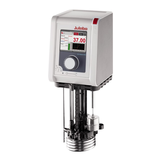
Refrigerated circulator circulator Circulator with closed Circulator with cooling DYNEO DD Circulator stainless steel bath tank. machine. Example: Example: DYNEO DD-BC6 for DYNEO DD-601F for standard temperature control temperature applications applications in the bath or externally Function description This section describes the function of the device. -
Page 17: Operating And Functional Elements
Product description Operating and functional elements The following figure shows the operating and functional elements and their position on the unit. Control and function elements Mains switch Display Central controller High temperature cut-off setting Internal/external flow direction setting USB interface Type A USB interface Type B CAN plug for connection with a cooling machine Interface for external temperature sensor... -
Page 18: Interfaces
Product description Interfaces This section describes the electronic interfaces on the device. For safe operation, the interfaces must be operated according to their corresponding permissible specifications. 5.4.1 Connection of Pt100 temperature sensor The plug ext. Pt100 is used to connect an external Pt100 temperature sensor. The following section describes the wiring of the plug as well as the connection cable of the temperature sensor. -
Page 19: Rs232 Interface (Optional)
Product description 5.4.2 RS232 interface (optional) The RS232 interface is a 9-pin D-Sub socket for connecting the device to a PC. RS232 plug RS232 interface pin assignment Pin 2 RxD receive data Pin 7 RTS request to send Pin 3 TxD transmit data Pin 8 CTS clear to send... -
Page 20: Analog Interfaces (Option)
Product description Analog interfaces (option) The analogue interfaces are optional and installed ex works. Slide-in module with analogue connections Alarm output REG/EPROG plug Standby input 5.5.1 Alarm output The alarm output is a potential-free changeover contact, through which an externally connected circuit can be switched. Alarm output diagram 1.888.610.7664 www.calcert.com... -
Page 21: Reg/Eprog Socket
Product description In the <Analog module> menu, a defined state can be selected as the trigger for the <Alarm output>. When the respective state is reached, pins 2 and 3 are connected: • Standby • Alarm • Alarm + Standby When the respective state is reached, pins 1 and 2 are connected: •... -
Page 22: Standby Input
Product description 5.5.3 Standby input With the standby socket the device can be put in standby mode using an external signal transmitter. [1] External contact, e.g. switch [2] Pin 3 [3] Pin 1 [4] Pin 2 Standby socket diagram 1.888.610.7664 www.calcert.com sales@calcert.com... -
Page 23: Operating Interface
Product description Operating interface The device is operated using the central controller. When it is switched on, the display shows the home screen. The [Display] softkey toggles between three different views of the home screen. Home screen [1] Internal/external temperature control [2] Start/Stop [3] [Menu] softkey opens the <Main menu>... -
Page 24: Operation With The Central Controller
Product description 5.6.1 Operation with the central controller The central controller is used to control all menu functions and inputs on the user interface. Selected menus, softkeys or input fields are highlighted in red. Turning: • navigates between menus, buttons and input fields •... -
Page 25: Alarm Messages
Product description Symbol Description Heating is active Cooling is active Alarm message Warning message Alarm messages Errors or disturbances are indicated on the Home screen by alarm messages or warnings. A help text is displayed by pressing the warning symbol with the central controller. -
Page 26: Operator Messages
Product description Display of warning message Warning: In the event of a warning, the tempering process is not interrupted. A warning message with a yellow background is display. A signal tone is emitted at intervals. The acoustic signal can be deactivated by pressing the central controller. -
Page 27: Main Menu
Product description Main menu Bring up the Main menu using the [Menu] softkey on the home screen. The Main menu is divided into menu options, which respectively contain more submenus or in which settings can be specified. You can always get back to the home screen using the [Home] softkey. -
Page 28: Thermodynamics Menu
Product description 5.9.3 Thermodynamics menu The control parameters for the temperature sequence are defined and the pump capacity is set in the menu <Thermodynamics>. Adjust controller: • Setting for the control parameters for internal or external control • Definition of the control behavior •... -
Page 29: Service Menu
Actuating variable • Start up behavior 5.9.7 Service menu The menu <Service> is reserved for JULABO service technicians and password protected. 5.9.8 Install unit menu In the menu <Install unit> several basic settings are specified. Depending on the device configuration, not all menu functions may be available. -
Page 30: Technical Data
Product description 5.10 Technical data Performance specifications measured in accordance with DIN12876. Cooling capacities up to 20°C measured with ethanol; over 20°C with thermal oil unless specified otherwise. Performance specifications apply at an ambient temperature of 20°C. Performance values may differ with other bath fluids. Grouping of the device acc. - Page 31 Product description DYNEO DD Temperature control application Working temperature range °C +20 … +200 Temperature stability °C ±0.01 Temperature resolution °C 0.01 Temperature control PID3 Temperature setting Digital ATC sensor adjustment 3-point adjustment Pump Volume flow l/min 8 … 27 Supply pressure 0.1 …...
-
Page 32: Material Of Parts That Come Into Contact With The Medium
Product description 5.10.1 Material of parts that come into contact with the medium The table lists parts that could come into contact with the bath fluid as well as the material that the parts are made of. This data can be used to check the compatibility of the parts with the bath fluid used. -
Page 33: Technical Data For Refrigerated Circulators
Product description 5.10.2 Technical data for refrigerated circulators This section lists the technical data of the refrigerated circulator. Technical data DYNEO DD-200F Working temperature range °C -20 … +200 Cooling capacity °C 0.20 0.17 0.15 0.10 0.02 Refrigerant R134A Dimensions... - Page 34 Product description Technical data DYNEO DD-300F Working temperature range °C -25 … +200 Cooling capacity °C 0.30 0.30 0.27 0.19 0.08 Refrigerant R134A Dimensions Dimensions (W x D x H) 24 x 42 x 66 Usable bath opening 13 x 15 Bath depth Volumes min.
- Page 35 Product description Technical data DYNEO DD-449F Working temperature range °C -30 … +200 Cooling capacity °C 0.44 0.35 0.27 0.20 0.06 Refrigerants R290 Dimensions Dimensions (W x D x H) 39 x 62 x 75 Usable bath opening 28 x 35 Bath depth Volumes min.
- Page 36 Product description Technical data DYNEO DD-600F Working temperature range °C -35 … +200 Cooling capacity °C R452A* 0.60 0.54 0.50 0.33 0.19 0.07 R449A 0.60 0.54 0.44 0.27 0.16 0.04 Refrigerant R449A, R452A* Dimensions Dimensions (W x D x H)
- Page 37 Product description Technical data DYNEO DD-900F Working temperature range °C -38 … +200 Cooling capacity °C 0.90 0.85 0.80 0.52 0.31 0.11 Refrigerant R449A Dimensions Dimensions (W x D x H) 39 x 62 x 75 Usable bath opening 26 x 35 Bath depth Volumes min.
- Page 38 Product description Technical data DYNEO DD-1001F Working temperature range °C -38 … +100 Cooling capacity °C 1.00 0.95 0.85 0.60 0.32 0.12 Refrigerant R449A Dimensions Dimensions (W x D x H) 45 x 64 x 95 Usable bath opening 35 x 41 Bath depth Volumes min.
-
Page 39: Bath Fluids
Recommended bath fluids and further information can be found on our website NOTE No liability accepted for usage of bath fluids that are not suitable! Unsuitable bath fluids that are not approved by JULABO can damage the water bath. • Use bath fluids that are recommended by JULABO •... -
Page 40: Hoses
Product description 5.10.4 Hoses Hoses for connection of an external system must suit the working temperature range and the respective temperature control application. Hoses for every area of application can be found on our website. Hoses must meet the following requirements: •... -
Page 41: Transport And Installation
Transport and installation Transport and installation This section describes how to transport the unit safely. Transporting the device A circulator can be transported with the cooling machine when mounted. CAUTION Risk of crushing by falling device! A device that is not secured appropriately can fall down during improper transport and cause crushing injuries. -
Page 42: Install The Device At The Operating Location
Transport and installation Install the device at the operating location This section describes how the device is set up at the installation location. The device has been transported to the operation location. The size and infrastructure of the operation location are suitable for device operation. -
Page 43: Initial Operation
Initial operation Initial operation Mounting the circulator 7.1.1 Mount heating or refrigerated circulator In the case of a heating circulator or a refrigerated circulator, the circulator is mounted on the closed bath or on cooling machine. If the circulator is disassembled, e.g. due to a change of device or for service purposes, it can then be easily reassembled with the connecting box. -
Page 44: Connect The Device To The Power Supply
Initial operation Connect the device to the power supply 7.2.1 Connect bridge mounted or heating circulator This section describes how the circulator is connected as a bridge mounted circulator or heating circulator. The circulator is mounted as a bridge mounted or heating circulator. ... -
Page 45: Connect Refrigerated Circulator
Initial operation 7.2.2 Connect refrigerated circulator This section describes how the circulator is connected as a refrigerated circulator. The circulator is mounted on a refrigeration unit. The connection cable, mains cable and CAN bus cable are ready for use. 1. -
Page 46: Connecting An External System
Initial operation Connecting an external system The device is designed for tempering external, closed loop systems. An external system is connected to the unit’s pump connections. CAUTION Risk of burns due to damaged temperature control hoses! Hot bath fluid can escape from damaged temperature control hoses and cause serious burns when it comes into contact with skin. -
Page 47: Connect An External System With Screw Connections
Initial operation NOTE Overflowing bath fluid due to externally connected systems! If the externally connected system is higher than the temperature control system, bath fluid can flow back and overflow when switched off. • Position the connected external system on the same level or lower than the temperature control system •... - Page 48 Initial operation 2. Remove the sealing plugs. 3. Screw the hoses onto the pump connections by hand. Pay attention to the supply and runback position. 4. Carefully tighten the pump connections with a maximum torque of 3 Nm. Brace the nut (width across flats: 17 mm) using an open-end wrench. ...
-
Page 49: Connect An External System With Barbed Fittings
Initial operation 7.3.2 Connect an external system with barbed fittings This section describes how to connect an external, closed system to the device using barbed fittings. Open-end wrench, 17 mm Open-end wrench, 19 mm Torque wrench The circulator is equipped with the optional assembly frame or pump set. ... -
Page 50: Switch On The Device And Set The Language
Initial operation The external system is connected. If the external system is disassembled, the pump connections must be resealed with the sealing plugs so that no bath fluid can splash out during operation. Switch on the device and set the language The language must be set first, to prepare for important basic settings. -
Page 51: Fill Device
Initial operation 2. Press the [Display] softkey to select the home screen that displays the high temperature cut-off value. 3. Use the screwdriver to set the overtemperature protection device. The display shows the set value. 4. Set a value that is at least 25 K under the flash point of the bath fluid being used. -
Page 52: Set Up Power Supply For The Refrigerated Circulator
Initial operation Set up power supply for the refrigerated circulator For a refrigerated circulator, the power supply is configured at the factory. The circulator is supplied with power from the refrigeration unit. Alternatively, both units can be connected to separate circuits with one power cable each. The type of power supply is set in the operating menu. -
Page 53: Set Chiller Mode
Initial operation The device is switched off. Bath fluid is filled. 1. Set the lever to a low level for internal circulation (e.g. position 2 from the right stop). 2. Switch on the device and check whether the flow of the bath fluid suits your application. -
Page 54: Set Limit Values
Initial operation 7.10 Set limit values 7.10.1 Set temperature warning limits The low temperature and high temperature are adjustable temperature limits that serve as warning limits for the device. If one of the warning limits is exceeded during the course of a tempering process, then the device warns with a signal tone and displays a warning message. -
Page 55: Adjusting Actual Value Limits
Initial operation 7.10.3 Adjusting actual value limits The actual value limits “internal minimum” and “internal maximum” are effective in the external control operating mode. They define limits for the expected temperature in the internal bath. The temperature controller cannot exceed these limit values. Under certain circumstances, the external setpoint will not be reached. -
Page 56: Setting Band Limit
Initial operation In order to gently control the temperature of a sample in an external system, or to protect a glass reactor from thermal stress, for example, maximum permissible temperature differences can be specified for the heating phase and the cooling phase. 7.10.5 Setting band limit The upper and lower band limit is defined in °K. -
Page 57: Operation
Operation Operation Switch on the unit This section describes how to switch on the device. The unit is connected and ready for operation. 1. Switch the unit on at the mains switch. The software boots and starts the unit. The display shows the unit name, voltage version and software version. -
Page 58: Basic Settings
Observe the following for heating circulators: For temperature control applications near or below the ambient temperature: Use a cooling coil or JULABO immersion cooler. Basic settings 8.4.1 Set language The language of the operating interface can be switched to one of the available languages. -
Page 59: Activate Autostart Function
Operation 8.4.3 Activate autostart function The autostart function makes it possible to start a temperature control application directly using the mains switch or via an intermediate timer. The device is configured ex works in such a ways that it switches to a safe operating status in the event of power failure. -
Page 60: Record Data
Operation Record data 8.5.1 Record measurement data Measurement data for an ongoing temperature control application can also be recorded onto a USB stick at the same time. The record documents the date, time, setpoint temperature, intern actual value, external actual value and the percentage power. -
Page 61: Displaying Alarm Memory
Operation 8.5.3 Displaying alarm memory Alarm messages are stored with date, time, alarm code and unit identifier. The data can be read out via the menu. The device is switched on. 1. Bring up the <Main menu>. 2. From the <Settings> submenu, select the menu option <Alarm memory>. -
Page 62: Thermodynamics
Operation Thermodynamics 8.6.1 Control parameter The device works with a PID control. Experience has shown that the control parameters set ex works achieve an optimal temperature sequence in the sample. The internal and external control parameters can be adjusted in the submenu <Control performance>. -
Page 63: Optimizing Temperature Curves
Operation 8.6.2 Optimizing temperature curves The temperature sequence shown on the display provides information about how individual control parameters can be optimized to achieve a better result. Optimal temperature sequence, temperature quickly reaches the setpoint without overshooting, and keeps the setpoint. Symptom: Temperature sequence slowly approaches the setpoint and doesn’t quite reach it. -
Page 64: Adjust Controller
Operation 8.6.3 Adjust controller In the menu <Adjust controller> the individual control parameters for internal and external control can be set. The device is switched on. 1. Bring up the <Main menu>. 2. From the <Thermodynamics> submenu, select the menu option <Adjust controller>. -
Page 65: Remote Control Device
Operation The minimum value is defined internally. The maximum value is limited to the adjustable maximum pump power in the menu <Setpoint limits>. 4. Activate the desired pump mode. The pump is set. To achieve low setpoint temperatures, it may be helpful to reduce the pump output in certain situations. -
Page 66: Set Rs232 Interface Parameters
Operation 8.7.2 Set RS232 interface parameters The interface parameters cannot be changed during remote control mode. If they differ from the factory settings, they must be set before remote control mode is activated. Remote control is deactivated. 1. Call up the <Main menu> on the unit. 2. -
Page 67: Set Eprog Input
Operation 8.7.4 Set EPROG input The EPROG input can be used to send an external voltage or current signal to the circulator. Depending on the setting, the circulator interprets the input signals as a setpoint temperature, power capacity, flow or pressure, and can output the values as a display on the start screen. -
Page 68: Set Up Actuating Variable
Operation 8.7.6 Set up actuating variable If the device is in remote control mode then the variable (capacity) with which the cooling unit or heater is controlled can be set using interface commands. This section describes how the actuating variable can be set. ... -
Page 69: Setting The Timer
Operation NOTE Falling bath fluid level! In the case of a prolonged temperature control application, the level of bath fluid in the bath tank can fall below the alarm limit due to evaporation. A low liquid level alarm is triggered and temperature control application stops. •... -
Page 70: Delete Temperature Control Profile
Operation 3. Select one of the eight profiles and confirm your selection. The selected profile changes to red. 4. Bring up the <Edit> submenu. In the dialog window, the selected temperature control profile is displayed as an editable table with profile number, selected step, and total number of steps. -
Page 71: Set Profile Timer
Operation 8.8.4 Set profile timer Temperature control sequences can be individually programmed for individual temperature control profiles in the <Profile timer> submenu. The device is switched on. 1. Bring up the <Main menu>. 2. From the <Programmer> submenu, select the menu option <Profile timer>. -
Page 72: Configure Signal Outputs
Operation 8. In the <Final state> field, select how the device should behave after the profile series expires. 9. Enable the <Active> field to activate the profile series. The profile series is programmed and active. It starts at the programmed start time on the specified start date and runs through the specified number of temperature control applications on the specified weekdays. -
Page 73: Activating Stand-By Input
Operation 8.10 Activating stand-by input This section describes how standby input can be activated. The device is switched on. The electronics slide-in module with analog connections is installed. 1. Bring up the <Main menu>. 2. Bring up the <Connect unit> submenu. 3. -
Page 74: Adjust External Temperature Sensor
Operation 3. From the <Install unit> submenu, select the menu option <Adjust sensor>. 4. Set the internal mode to inactive. The input fields are unlocked. 5. Enter the desired setpoint for internal in the first line and confirm your entry. -
Page 75: Device Reset
Operation 8.12 Device Reset The function resets the device to the factory settings. The device is switched on. 1. Bring up the <Main menu>. 2. Call up the <Reset device> menu item in the <Install device> submenu. 3. If you want to reset the device, confirm the security prompt with [OK]. ... -
Page 76: Maintenance
See type plate for mains voltage and current value. We recommend only using original JULABO spare parts. Check safety symbols The safety labels affixed to the device must be clearly legible at all times. Their condition must be checked every two years. -
Page 77: Test The Low Liquid Level Safety Function
Maintenance Test the low liquid level safety function This section describes how you can test that the low liquid level safety function is operational. The device is switched on. 1. Remove the bath lid. 2. Using a long object, e.g. a straightedge, carefully push the thermostat float downwards until it reaches its mechanical stop. -
Page 78: Clean Device
Maintenance Clean device The circulator and bath tank, and also a cooling machine if connected, should be cleaned from time to time. In addition to this, the device must be appropriately decontaminated if hazardous substances have been spilled on or into the device. ... -
Page 79: Device Storage
Maintenance Device storage This section describes how to store the device. The device is switched off and disconnected from the mains voltage. 1. Empty all system components completely. 2. Clean the device. 3. Carefully dry the device and all its system components, e.g. with compressed air. -
Page 80: Warranty
Maintenance Warranty JULABO provides a warranty that the device will function perfectly as long as it is connected and used correctly and as described in the operating manual. The warranty period is one year from the invoice date. With the 1PLUS warranty, the warranty can be extended to two years free of charge. -
Page 81: Disposal
Disposal 10 Disposal 10.1 Device disposal When disposing of the device, the applicable country-specific guidelines must be observed. The circulator combination is switched off and disconnected from the mains voltage. 1. Empty the bath tank or cooling machine completely. 2. -
Page 82: Ec Declaration Of Conformity
EC Declaration of Conformity 11 EC Declaration of Conformity 1.888.610.7664 www.calcert.com sales@calcert.com... -
Page 83: Declaration Of Conformity
UK Declaration of Conformity 12 UK Declaration of Conformity UK Office: JULABO UK Ltd., Unit 7, Casterton Road Business Park, Old Great North Road, Little Casterton, Stamford, PE9 4EJ, United Kingdom, Tel.: +44 1733 265892 1.888.610.7664 www.calcert.com sales@calcert.com... -
Page 84: Appendix
Appendix 13 Appendix 13.1 Interface commands Interface commands allow the device to be remote controlled. Parameters can be retrieved and the current status can be queried. To do this, the device must be connected to the master computer via a digital interface. Interface commands are entered using a terminal program. - Page 85 Appendix Setpoints and warning System response limits in_sp_00 Set setpoint temperature in_sp_03 Set high temperature warning limit in_sp_04 Set low temperature warning limit in_sp_05 Set working temperature via EPROG in_sp_06 Setpoint temperature set via watchdog function in_sp_07 Set pump stage (1 … 4) in_sp_10 Set actuating variable specification via serial interface in_sp_11...
- Page 86 Appendix in_mode_08 Controller dynamics set with internal temperature control: 0 = Aperiodic 1 = Standard in_mode_11 Actuating variable source: 0 = Circulator 1 = Serial 2 = Analog (EPROG) IN PAR System response in_par_00 Set sensor difference between working temperature sensor and safety temperature sensor in_par_01 Set time constant of the external bath TE...
-
Page 87: Out Commands
Appendix 13.1.2 OUT commands OUT commands set device parameters. Remote control mode must be active. Parameter Parameter Setting settings out_sp_00 xxx.xx Setting for the setpoint temperature out_sp_03 xxx.xx Setting for the high temperature out_sp_04 xxx.xx Setting for the low temperature out_sp_06 xxx.xx Setpoint temperature setting via watchdog function... - Page 88 Appendix out_mode_08 Setting of the internal control dynamic: 0 = Aperiodic 1 = Standard out_mode_11 Actuating variable source: 0 = Thermostat 1 = Serial 2 = Analog (EPROG) System parameter Parameter Setting out_par_04 Setting the Cospeed control parameter for internal control out_par_06 Setting of the control parameter XP for internal...
-
Page 89: Status Commands
Appendix Auxiliary Parameter Setting parameters out_hil_00 -xxx Setting of the actuating variable limit for cooling capacity (0-100%) out_hil_01 Setting of the actuating variable limit for heating capacity (0-100%) 13.1.3 Status commands Status commands are used to query the current status of the device. Status commands System response version... -
Page 90: Alarms And Warnings
Appendix 13.2 Alarms and Warnings If the device is connected to a network and remotely controlled, a status query via interface command will output any pending alarms or warnings as text. Alarm and warning messages are described in the table. If a displayed error code is not described in the table or the error is still pending after switching off and on again, please contact Technical Service. - Page 91 Appendix The setpoint value is set to external • Check whether an external temperature sensor, but no signal is temperature sensor is connected or available. whether the electrical connection is interrupted. • If necessary, adjust the setpoint value. The early warning system for low •...
- Page 92 Appendix -116 The alarm latch of the protective • Switch off the unit at the mains switch, equipment is still active. wait 4 seconds and then switch the unit on again. Pressure sensor detects excessive • -427 Check ambient temperature and condensation pressure.
- Page 93 Appendix -1431 The minimum permissible current • Check mains voltage for nominal consumption at the compressor has voltage. The specified voltage been fallen short of. tolerance of the unit must not be exceeded. • Check the mains cable of the refrigeration unit for damage and replace if necessary.
Need help?
Do you have a question about the DYNEO DD and is the answer not in the manual?
Questions and answers