
Subscribe to Our Youtube Channel
Related Manuals for Allen-Bradley Rockwell Automation 857


Summary of Contents for Allen-Bradley Rockwell Automation 857
- Page 1 857 Protection System For Feeder and Motor Protection Bulletin 857, Series A User Manual...
- Page 2 Important User Solid-state equipment has operational characteristics differing from those of electro- Information mechanical equipment. Safety Guidelines for the Application, Installation and Maintenance of Solid-State Controls (Publication SGI-1.1 available from your local Rockwell Automation sales office or online at http://literature.rockwellautomation.com) describes some important differences between solid-state equipment and hard-wired electromechanical devices.
-
Page 3: Table Of Contents
Table of Contents Chapter 1 Overview Introduction ................1-1 Main Relay Features ..............1-1 User Interface ................1-4 Operating Safety ..............1-4 Chapter 2 Local Panel User Relay Front Panel ..............2-1 Interface Display ................2-1 Menu Navigation and Pointers ......... 2-3 Keypad ................2-3 Operation Indicators ............ - Page 4 Table of Contents Chapter 3 Protection Functions Maximum Number of Protection Stages ........ 3-1 Protection Functions ............... 3-1 General Features of Protection Stages ........3-2 Setting Groups ..............3-2 Forcing Start or Trip Condition for Testing ..... 3-2 Forcing Start or Trip Condition for Testing Purposes ..3-2 Start and Trip Signals ............
- Page 5 Table of Contents Earth Fault Protection I > (50N/51N) ........3-30 Input Signal Selection ............ 3-31 Intermittent Earth Fault Detection ........3-31 Four or Six Independent Undirectional Earth Fault Overcurrent Stages ........... 3-31 Inverse Operation Time (I > stage only) ......3-32 Inverse Time Limitation ..........
- Page 6 Table of Contents Chapter 3 Protection Functions Overfrequency and Underfrequency Protection f>, f< (cont.) (81H/81L) ..............3-57 Protection Mode for f>< and f><>< Stages ....3-57 Undervoltage Self Blocking of Underfrequency Stages .. 3-57 Initial Self Blocking of Underfrequency Stages ..... 3-57 Four Independent Frequency Stages ......
- Page 7 Table of Contents Chapter 4 Supporting Functions Event Log ................4-1 Event Enabling/Masking ..........4-1 Event Buffer Overflow ............. 4-2 Disturbance Recorder ............. 4-2 Triggering the Recorder ........... 4-2 Reading Recordings ............4-2 Number of Channels ............4-3 Cold Load Pick-up and Inrush Current Detection ....4-5 Cold Load Pick-up ............
- Page 8 Table of Contents Chapter 5 Measurement Functions Measurement Accuracy ............5-1 RMS Values ................5-2 RMS Currents ..............5-2 RMS Voltages ..............5-2 Harmonics and Total Harmonic Distortion (THD) ....5-3 Demand Values ............... 5-3 Minimum and Maximum Values ..........5-4 Maximum Values of the last 31 days and 12 months .....
- Page 9 Table of Contents Chapter 7 Communications Communication Ports ..............7-1 Local Port ................ 7-1 Remote Port X9 ..............7-3 Extension Port ..............7-5 Optional 61850 Interface ..........7-5 Communication Protocols ............7-6 PC Communication ............7-6 Modbus TCP and Modbus RTU........7-6 Probibus DP ..............
- Page 10 viii Table of Contents Chapter 10 Technical Data Connections ................10-1 Measuring Circuitry ............10-1 Auxiliary Voltage ............10-1 Digital Inputs ..............10-2 Trip Contacts ..............10-2 Alarm Contacts ............... 10-2 Local Serial Communication Port ........10-3 Remote Control Connection ........... 10-3 Arc Protection Interface (Option) ........
- Page 11 Table of Contents Power Protection ............10-16 Reverse Power and Under-Power Stages ....10-16 Synchrocheck Function ..........10-16 Circuit-Breaker Failure Protection ....... 10-17 Arc Fault Protection Stages (Option) ......10-17 Arc Protection Stage ArcI> (50AR), Option ..10-17 Arc Protection Stage ArcI >...
- Page 12 Table of Contents 857-UM001A-EN-P – July 2009...
-
Page 13: Chapter 1 Overview
Chapter Overview Introduction The Allen-Bradley 857 motor and feeder protection device includes all the essential protection functions needed to protect feeders and motors in distribution networks of utilities, heavy industry, power plants and offshore applications. Further, the device includes many... - Page 14 Introduction Main Relay Features (cont.) • Recording of events and fault values into an event register from which the data can be read via a keypad and a local HMI or by means of a PC based configuration software • All settings, events and indications are in non-volatile memory.
- Page 15 Introduction Table 1.1 – List of Protection Functions (cont.) IEEE/ IEC symbol Function name Note ANSI code f<, f<< Underfrequency protection df/dt Rate of change of frequency (ROCOF) protection ∆f, ∆U, ∆φ Synchrocheck 50BF CBFP Circuit-breaker failure protection Prg1...8 Programmable stages 50ARC/ ArcI>, ArcI >,...
-
Page 16: User Interface
Introduction User Interface The relay can be controlled in three ways: • Locally with the push-buttons on the relay front panel • Locally using a PC connected to the serial port on the front panel or on the rear panel of the relay (both cannot be used simultaneously) •... -
Page 17: Chapter 2 Local Panel User Interface
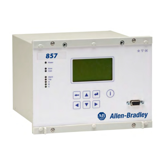
The figure below shows, as an example, the front panel of the Allen- Bradley 857 relay and the location of the user interface elements used for local control. Figure 2.1 – Front Panel of Allen-Bradley 857 Relay 1. LCD dot matrix display 2. Keypad 3. - Page 18 Local Panel User Interface 1. Freely configurable single-line diagram 2. Five controllable objects 3. Six object statuses 4. Bay identification 5. Local/Remote selection 6. Auto-reclose on/off selection (if applicable) 7. Freely selectable measurement values (max. six values) Figure 2.3 – Sections of the LCD Matrix Display 8.
-
Page 19: Menu Navigation And Pointers
Local Panel User Interface Menu Navigation and Pointers 1. Use the arrow keys UP and DOWN to move up and down in the main menu, that is, on the left-hand side of the display. The active main menu option is indicated with a cursor. The options in the main menu items are abbreviations, e.g. -
Page 20: Operation Indicators
Local Panel User Interface Operation Indicators The relay is provided with eight LED indicators: Power Error Alarm Trip Figure 2.5 – Operation Indicators of the Relay Table 2.1 – Operation Indicators LED indicator Meaning Remarks Power LED lit The auxiliary power has been Normal operation state switched on Error LED lit... -
Page 21: Resetting Latched Indicators And Output Relays
Local Panel User Interface Resetting Latched Indicators and Output Relays All the indicators and output relays can be given a latching function in the configuration. There are several ways to reset latched indicators and relays: • From the alarm list, move back to the initial display by pushing the CANCEL key for approx. - Page 22 Local Panel User Interface Local Panel Operations (cont.) Figure 2-6 – Example of Scroll Indication 4. Push the CANCEL key to cancel a selection. 5. Pushing the UP or DOWN key in any position of a sub-menu, when it is not selected, brings you directly one step up or down in the main menu.
-
Page 23: Main Menu
Local Panel User Interface 6. Push the INFO key to obtain additional information about any menu item. 7. Push the CANCEL key to revert to the normal display. Main Menu The general menu structure is shown in Figure 2.7. The menu is dependent on the user's configuration and the options according the order code. - Page 24 Local Panel User Interface Table 2.2 – List of the Local Main Menu (cont.) Main Number ANSI Description Note Menu of Menus code I< Undercurrent stage I2> Current unbalance stage T> Thermal overload stage Io> 1st earth fault stage 50N/51N Io>>...
-
Page 25: Menu Structure Of Protection Functions
Local Panel User Interface Table 2.2 – List of the Local Main Menu (cont.) Main Number ANSI Description Note Menu of Menus code ArcIo> Optional arc protection stage for earth faults. Current 50NARC input = I01 ArcIo2> Optional arc protection stage for earth faults. Current 50NARC input = I02 Object definitions... - Page 26 2-10 Local Panel User Interface Local Panel Operations This is the status, start and trip counter and setting group menu. The (cont.) content is: • Status – The stage is not detecting any fault at the moment. The stage can also be forced to pick-up or trip if the operating level is "Configurator"...
- Page 27 2-11 Local Panel User Interface This is the main setting menu. The content is: • Stage setting group 1 – These are the group 1 setting values. The other setting group can be seen by pressing push buttons ENTER and then RIGHT or LEFT. Setting groups are explained in section “Setting Groups”.
-
Page 28: Setting Groups
2-12 Local Panel User Interface Local Panel Operations • Flt 2.86xIn – The fault current has been 2.86 per unit. (cont.) • Load 0.99xIn – The average load current before the fault has been 0.99 pu. • EDly 81% – The elapsed operation delay has been 81% of the setting 0.60 s = 0.49 s. -
Page 29: Fault Logs
2-13 Local Panel User Interface Figure 2.12 – Example of I> Setting Submenu Fault Logs All the protection functions include fault logs. The fault log of a function can register up to eight different faults with time stamp information, fault values etc. Each function has its own logs (See Figure 2.13). -
Page 30: Operating Levels
2-14 Local Panel User Interface Local Panel Operations Operating Levels (cont.) The relay has three operating levels: User level, Operator level and Configurator level. The purpose of the access levels is to prevent accidental change of relay configurations, parameters or settings. -
Page 31: Opening Access
2-15 Local Panel User Interface Opening Access 1. Push the INFO key and the ENTER key on the front panel. ENTER PASSWORD Figure 2.15 – Opening the Access Level 2. Enter the password needed for the desired level: the password can contain four digits. -
Page 32: Operating Measures
2-16 Local Panel User Interface Operating Measures Control Functions The default display of the local panel is a single-line diagram including relay identification, Local/Remote indication, Auto-reclose on/off selection and selected analogue measurement values. Please note that the operator password must be active in order to be able to control the objects. -
Page 33: Measured Data
2-17 Local Panel User Interface Measured Data The measured values can be read from the main menus and their submenus. Furthermore, any measurement value in the following table can be displayed on the main view next to the single line diagram. - Page 34 2-18 Local Panel User Interface Operating measures (cont.) Table 2.3 – Measured Values (cont.) Value Menu/Submenu Description E+.nn E/DECIMAL COUNT Decimals of exported energy [ ] Eq.nn E/DECIMAL COUNT Decimals of reactive energy [ ] E-.nn E/DECIMAL COUNT Decimals of imported energy [ ] Ewrap E/DECIMAL COUNT Energy control...
- Page 35 2-19 Local Panel User Interface Table 2.3 – Measured Values (cont.) Value Menu/Submenu Description U/PHASE VOLTAGES Phase-to-earth voltage UL1 [V] U/PHASE VOLTAGES Phase-to-earth voltage UL2 [V] U/PHASE VOLTAGES Phase-to-earth voltage UL3 [V] U/SYMMETRIC VOLTAGES Residual voltage Uo [%] U/SYMMETRIC VOLTAGES Positive sequence voltage [%] U/SYMMETRIC VOLTAGES Negative sequence voltage [%]...
-
Page 36: Reading Event Register
2-20 Local Panel User Interface Operating measures (cont.) Reading Event Register The event register can be read from the Evnt submenu: 1. Push the RIGHT key once. 2. The EVENT LIST appears. The display contains a list of all the events that have been configured to be included in the event register. -
Page 37: Configuration And Parameter Setting
2-21 Local Panel User Interface 3. Push the ENTER key. 4. Push the UP or DOWN key to change the "OFF" text to "ON", that is, to activate the Force function. 5. Push the ENTER key to return to the selection list. Choose the signal to be controlled by force with the UP and DOWN keys, for instance the T1 signal. -
Page 38: Parameter Setting
2-22 Local Panel User Interface Configuration and Some of the parameters can only be changed via the RS-232 Parameter Setting serial port using the SetPointPS software. Such parameters, (for (cont.) example passwords, blockings and mimic configuration) are normally set only during commissioning. Some of the parameters require the restarting of the relay. -
Page 39: Setting Range Limits
2-23 Local Panel User Interface 6. Push the ENTER key to accept a new value. If you want to leave the parameter value unchanged, exit the edit state by pushing the CANCEL key. Figure 2.20 – Changing Parameters Setting Range Limits If the given parameter setting values are out-of-range values, a fault message will be shown when the setting is confirmed with the ENTER key. -
Page 40: Disturbance Recorder Menu Dr
2-24 Local Panel User Interface Configuration and Parameter Setting (cont.) Figure 2.22 – Allowed Setting Ranges shown in the Display Disturbance Recorder Menu DR Via the submenus of the disturbance recorder menu the following functions and features can be read and set: DISTURBANCE RECORDER •... -
Page 41: Configuring Digital Inputs Di
2-25 Local Panel User Interface • IL1RMS, IL2RMS, IL3RMS • ILmin, ILmax, ULLmin, ULLmax, ULNmin, ULNmax • fy, fz, U12y, U12z Configuring Digital Inputs DI The following functions can be read and set via the submenus of the digital inputs menu: •... -
Page 42: Configuration Menu Conf
2-26 Local Panel User Interface Configuration and Each stage of the protection functions can be disabled or enabled Parameter Setting individually in the Prot menu. When a stage is enabled, it will be (cont.) in operation immediately without a need to reset the relay. The relay includes several protection functions. - Page 43 2-27 Local Panel User Interface The rated CT secondary may also be less than the rated input but the measurement accuracy near zero current will decrease. DEVICE SETUP • Bit rate for the command line interface in ports X4 and the front panel.
- Page 44 Scaling for active, reactive and apparent power [Power]. The choices are k for kW, kvar and kVA or M for MW, Mvar and MVA. DEVICE INFO • Relay type (Type Allen-Bradley 865) • Serial number (SerN) • Software version (PrgVer) •...
-
Page 45: Protocol Menu Bus
2-29 Local Panel User Interface Protocol Menu Bus There are three communication ports in the rear panel. The availability depends on the communication options (see chapter Ordering code in the technical description). In addition there is a connector in the front panel overruling the local port in the rear panel. - Page 46 2-30 Local Panel User Interface Configuration and EXTENSION PORT Parameter Setting • Communication protocol for extension port X4 [Protocol]. (cont.) • Message counter [Msg#]. This can be used to verify that the device is receiving messages. • Communication error counter [Errors]. •...
- Page 47 2-31 Local Panel User Interface PROFIBUS Only one instance of this protocol is possible. • [Mode] • Bit rate [bit/s]. Use 2400 bps. This parameter is the bit rate between the main CPU and the Profibus ASIC. The actual Profibus bit rate is automatically set by the Profibus master and can be up to 12 Mbit/s.
- Page 48 2-32 Local Panel User Interface Configuration and TCP/IP [Ethernet] Parameter Setting These TCP/IP parameters are used by the ethernet interface module. (cont.) For changing the nnn.nnn.nnn.nnn style parameter values, SetPointPS is recommended. • IP address [IpAddr]. • Net mask [NetMsk]. •...
-
Page 49: Single Line Diagram Editing
2-33 Local Panel User Interface Single Line Diagram Editing The single-line diagram is drawn with the SetPointPS software. For more information, please refer to the SetPointPS manual, publication 857-PM001A-EN-P. 0.000A 0Kvar Figure 2.23 – Single Line Diagram Blocking and Interlocking Configuration The configuration of the blockings and interlockings is done with the SetPointPS software. -
Page 50: Setpoints Pc Software
Optional hardware is required. There is a free of charge PC program called SetPointPS available for configuration and setting of Allen-Bradley relays. Please download the latest SetPointPS.exe from our web page www.AB.com. For more information about the SetPointPS software, please refer to the programming manual, 857-PM001A-EN-P. -
Page 51: Maximum Number Of Protection Stages
Chapter Protection Functions Each protection stage can independently be enabled or disabled according to the requirements of the intended application. Maximum Number of The device limits the maximum number of enabled stages to about Protection Stages 30, depending of the type of the stages. For more information, in one application please see the configuration instructions under “Configuration and Parameter Settings”... -
Page 52: Setting Groups
Protection Functions General Features of Setting Groups Protection Stages Most stages have two setting groups. Changing between setting groups can be controlled manually or using any of the digital inputs, virtual inputs, virtual outputs or LED indicator signals. By using virtual I/O the active setting group can be controlled using the local panel mimic display, any communication protocol or using the inbuilt programmable logic functions. -
Page 53: Start And Trip Signals
Protection Functions Start and Trip Signals Every protection stage has two internal binary output signals: start and trip. The start signal is issued when a fault has been detected. The trip signal is issued after the configured operation delay unless the fault disappears before the end of the delay time. -
Page 54: Reset Time (Release Time)
(the dashed 40 ms pulse in the figure). In Allen-Bradley relays, the retardation time is less than 50 ms. -
Page 55: Hysteresis Or Dead Band
Protection Functions Hysteresis or Dead Band When comparing a measured value against a pick-up value, some amount of hysteresis is needed to avoid oscillation near equilibrium situation. With zero hysteresis any noise in the measured signal or any noise in the measurement itself would cause unwanted oscillation between fault-on and fault-off situations. -
Page 56: Current Protection Function Dependencies
Protection Functions Current protection function dependencies The current based protection functions are relative to I , which mode is dependent of the application mode. In the motor protection mode all of the current based functions are relative to I and in the feeder protection mode to I with following exceptions. -
Page 57: Inverse Time Limitation
Protection Functions Inverse Time Limitation The maximum measured secondary current is 50xI . This limits the scope of inverse curves with high pick-up settings. See “Inverse Time Operation” for more information. Cold Load and Inrush Current Handling See “Cold Load Pick-up and Inrush Current Detection”. Setting Groups There are two settings groups available for each stage. - Page 58 Protection Functions Table 3.2 – Parameters of the Overcurrent Stage I> (50/51) Parameter Value Unit Description Note Status Current status of the stage Blocked Start Trip TripTime Estimated time to trip SCntr Cumulative start counter TCntr Cumulative trip counter SetGrp 1 or 2 Active setting group SGrpDI...
-
Page 59: Recorded Values Of The Latest Eight Faults
Protection Functions Table 3.3 – Parameters of the Overcurrent Stages I>>, I>>> (50/51) Parameter Value Unit Description Note Blocked Status Current status of the stage Start Trip SCntr Cumulative start counter TCntr Cumulative trip counter SetGrp 1 or 2 Active setting group Digital signal to select the active setting group None Digital input... -
Page 60: Directional Overcurrent Protection I > (67)
3-10 Protection Functions Directional Overcurrent The Directional overcurrent protection can be used for Protection I > (67) directional short circuit protection. Typical applications are: Short circuit protection of two parallel cables or overhead lines in a radial network. Short circuit protection of a looped network with single feeding point. - Page 61 3-11 Protection Functions Two modes are available: directional and non-directional (Figure 3.8). In the non-directional mode the stage is acting just like an ordinary overcurrent 50/51 stage. +90° +90° -ind. -ind. +cap. +cap. 2° DIRECTIONAL NON-DIRECTIONAL 0° 0° VALUE VALUE +res.
-
Page 62: Four Independent Stages
3-12 Protection Functions Four independent stages There are four separately adjustable stages available: I >, I >>, >>> and I >>>>. Inverse operation time Stages I > and I >> can be configured for definite time or inverse time characteristic. See chapter Error! Reference source not found. - Page 63 3-13 Protection Functions Table 3.5 – Parameters of the Directional Overcurrent Stages I >, I >> (67) Parameter Value Unit Description Note Status Current status of the stage Blocked Start Trip Trip Time Estimated time to trip SCntr Cumulative start counter TCntr Cumulative trip counter SetGrp...
- Page 64 3-14 Protection Functions Table 3.5 – Parameters of the Directional Overcurrent Stages I >, I >> (67) (cont.) Parameter Value Unit Description Note ϕ ° Measured power angle Measured positive sequence voltage A, B, C, D, E User’s constants for standard equations. Type=Parameters.
-
Page 65: Recorded Values Of The Latest Eight Faults
3-15 Protection Functions Recorded values of the latest eight faults Detailed information is available on the eight latest faults: Time stamp, fault type, fault current, load current before the fault, elapsed delay and setting group. Table 3.7 – Recorded values of the directional overcurrent stages (8 latest faults) I >, I >>, I... - Page 66 3-16 Protection Functions , where I1 = I + aI I2 = I + aI ∠ ° − , a phasor rotating constant Table 3.8 – Setting parameters of unbalanced load function: I > (46R) Parameter Value Unit Default Description I2/I1>...
-
Page 67: Inverse Delay
3-17 Protection Functions Inverse delay The inverse delay is based on the following equation. Equation 3.1 , where ⎛ ⎞ ⎜ ⎜ ⎟ ⎟ − ⎝ ⎠ Operation time Delay multiplier Measured and calculated negative sequence phase current of fundamental frequency. Nominal current of the motor Pick-up setting I >... - Page 68 3-18 Protection Functions CurrentUnbalanceChar 2000 1000 K = 40 % K = 70 % K = 2 % K = 50 s K = 2 % K = 40 % K = 70 % Note: The longest delay is limited to 1000 seconds K = 1 s (=16min 40s).
-
Page 69: Recorded Values Of The Latest Eight Faults
3-19 Protection Functions Recorded values of the latest eight faults Detailed information is available on the eight latest faults: Time stamp, unbalance current, elapsed delay and setting group. Table 3.11 – Recorded values of the current unbalance stage (8 latest faults) I >... - Page 70 3-20 Protection Functions Equation 3.2 START , where START MEAS Operation time Start current of the motor. Default 6.00xI START Measured current during start MEAS Maximum allowed start time for the motor START TIME START IstartMin CURRENT START Figure 3.12 – Operation time delay of the stall protection stage Ist> If the measured current is less than the specified start current I START the operation time will be longer than the specified start time T...
-
Page 71: Frequent Start Protection N> (66)
3-21 Protection Functions Table 3.13 – Parameters of the stall protection stage: I > (48) Parameter Value/unit Description Setting values ImotSt xImot Nominal motor starting current Ist> %Imot Motor start detection current. Must be less than initial motor starting current. Type Operation charact./ definite time Operation charact./ inverse time... - Page 72 3-22 Protection Functions STOP START Open Close coil coil VAMP relay Output matrix Note: The relay A1 has been configured to be “normal closed”. The start is just an I> start alarm telling that there is only one start left at the moment.
-
Page 73: Undercurrent Protection I< (37)
3-23 Protection Functions Undercurrent Protection The undercurrent unit measures the fundamental frequency I< (37) component of the phase currents. The stage I< can be configured for definite time characteristic. The undercurrent stage is protecting rather the device driven by the motor e.g. -
Page 74: Polarization
3-24 Protection Functions Polarization The negative zero sequence voltage –U is used for polarization i.e. the angle reference for I . This –U voltage is measured via energizing input U or it is calculated from the phase voltages internally depending on the selected voltage measurement mode (see “Voltage Measurement Mode”... -
Page 75: Input Signal Selection
3-25 Protection Functions • Sector This mode is used with networks earthed with a small resistance. In this context "small" means, that a fault current may be more than the rated phase currents. The trip area has a shape of a sector as drawn in Figure 3.17. The base angle is usually set to zero degrees or slightly on the lagging inductive side (i.e. -
Page 76: Inverse Operation Time
3-26 Protection Functions Inverse operation time Inverse delay means that the operation time depends on the amount the measured current exceeds the pick-up setting. The bigger the fault current is the faster will be the operation. Accomplished ϕ> and I ϕ>>. - Page 77 3-27 Protection Functions Figure 3.17 – Two example of operation characteristics of the directional earth fault stages in sector mode Note: The drawn I phasor in both figures is inside the trip area. The angle offset and half sector size are user’s parameters. Table 3.16 –...
- Page 78 3-28 Protection Functions Table 3.16 – Parameters of the directional earth fault stages I >, I >> (67N) (cont.) Parameter Value Unit Description Note IoRes Resistive part of I (only when "InUse"=Res) IoCap Capacitive part of I (only when "InUse"=Cap) Io >...
-
Page 79: Recorded Values Of The Latest Eight Faults
3-29 Protection Functions Table 3.16 – Parameters of the directional earth fault stages I >, I >> (67N) (cont.) Parameter Value Unit Description Note X6-7,8,9. See chapter Error! Input Reference source not found.. X6-10,11,12 IoCalc IL1 + IL2 + IL3 Io1Peak ϕ>... -
Page 80: Earth Fault Protection I > (50N/51N)
3-30 Protection Functions Earth fault protection Undirectional earth fault protection is used to detect earth faults in > (50N/51N) low impedance earthed networks. In high impedance earthed networks, compensated networks and isolated networks undirectional earth fault can be used as back-up protection. The undirectional earth fault function is sensitive to the fundamental frequency component of the residual current 3I . -
Page 81: Input Signal Selection
3-31 Protection Functions Input Signal Selection Each stage can be connected to supervise any of the following inputs and signals: • Input I for all networks other than rigidly earthed • Input I for all networks other than rigidly earthed •... -
Page 82: Inverse Operation Time (I > Stage Only)
3-32 Protection Functions Inverse Operation Time (I > stage only) Inverse delay means that the operation time depends on the amount the measured current exceeds the pick-up setting. The bigger the fault current is, the faster will be the operation. Accomplished inverse delays are available for the I >... - Page 83 3-33 Protection Functions Table 3.18 – Parameters of the Undirectional Earth Fault Stage I > (50N/51N) (cont.) Parameter Value Unit Description Note The supervised value according the parameter "Input" below. IoCalc IoPeak Io2Peak I’oCalc Io> Pick-up value scaled to primary value Io>...
- Page 84 3-34 Protection Functions Table 3.19 – Parameters of the Undirectional Earth Fault Stage I >>, I >>>, >>>> (50N/51N) Parameter Value Unit Description Note Status Current status of the stage Blocked Start Trip TripTime Estimated time to trip SCntr Cumulative start counter TCntr Cumulative trip counter SetGrp...
-
Page 85: Recorded Values Of The Latest Eight Faults
3-35 Protection Functions Recorded Values of the Latest Eight Faults Detailed information is available on the eight latest earth faults: Time stamp, fault current, elapsed delay and setting group. Table 3.20 – Parameters of the Undirectional Earth Fault Stages (8 latest faults) I >, I >>, I >>>, I... -
Page 86: Direction Algorithm
3-36 Protection Functions Direction algorithm The function is sensitive to the instantaneous sampled values of the residual current and residual voltage. The selected voltage measurement mode has to include a direct –U measurement. pick-up sensitivity The sampling time interval of the relay is 625 μs at 50 Hz (32 samples/cycle). -
Page 87: Auto Reclosing
3-37 Protection Functions Auto reclosing The start signal of any Iϕ> stage initiating auto reclosing (AR) can be used to block the I > stage to avoid the I > stage with a long intermittent setting to interfere with the AR cycle in the middle of discrimination time. -
Page 88: Setting Groups
3-38 Protection Functions The fourth and the next faults do occur after release time but within release time + intermittent time. Thus the operation delay counter is advanced at every fault in the case the intermittent time setting is more than 100 ms (the lower status lines in the figure) and finally a trip signal is issued at t=0.87 s. -
Page 89: Recorded Values Of The Latest Eight Faults
3-39 Protection Functions Table 3.21 – Parameters of the directional intermittent transient earth fault stage I > (67NT) Parameter Value Unit Description Note Status Current status of the stage Blocked Start Trip SCntr Cumulative start counter TCntr Cumulative trip counter SetGrp 1 or 2 Active setting group... -
Page 90: Capacitor Bank Unbalance Protection
This natural unbalance current affects the settings, thus, the setting has to be increased. X1:1 X1:2 X1:3 X1:4 X1:5 X1:6 X1:7 X1:8 X1:9 X1:10 VAMP 255 Figure 2.23 – Typical capacitor bank protection application with Allen-Bradley devices 857-UM001A-EN-P – July 2009... -
Page 91: Compensation Method
3-41 Protection Functions Compensation method The sophisticated method for unbalance protection is to compensate the natural unbalance current. The compensation is triggered manually when commissioning. The phasors of the unbalance current and one phase current are recorded. This is because one polarizing measurement is needed. - Page 92 3-42 Protection Functions Table 3.23 – Setting parameters of capacitor bank unbalance protection: >>>, I >>>> (50N/51N) Parameter Value Unit Default Description Input Io1; Io2; IoCalc Current measurement input. NOTE! Do not use the calculated value which is only for earth fault protection purposes Io>>>...
- Page 93 3-43 Protection Functions Table 3.24 – Measured and recorded values of capacitor bank unbalance protection: I >, I >> (50N/51N) Parameter Value Unit Default Description Measured unbalance current values (including the natural unbalance current) Compensated unbalance current Display Io>>>, Io>>>> Setting value Recorded SCntr...
-
Page 94: Zero Sequence Voltage Protection U > (59N)
3-44 Protection Functions Zero sequence voltage The zero sequence voltage protection is used as unselective backup protection U > (59N) for earth faults and also for selective earth fault protections for motors having a unit transformer between the motor and the busbar. This function is sensitive to the fundamental frequency component of the zero sequence voltage. -
Page 95: Recorded Values Of The Latest Eight Faults
3-45 Protection Functions Figure 2.24 – Block diagram of the zero sequence voltage stages U > and U >> Table 3.25 – Parameters of the residual overvoltage stages U >, U >> (59N) Parameter Value Unit Description Note Status Current status of the stage Blocked Start Trip... -
Page 96: Thermal Overload Protection T> (49)
3-46 Protection Functions Table 3.26 – Recorded values of the residual overvoltage stages >, U >> (59N) Parameter Value Unit Description yyyy-mm-dd Time stamp of the recording, date hh:mm:ss.ms Time stamp, time of day Fault voltage relative to Un/√3 EDly Elapsed time of the operating time setting. -
Page 97: Time Constant For Cooling Situation
3-47 Protection Functions θ × × Preload current, θ temperature rise is 120% ). This parameter is the memory of the algorithm and corresponds to the actual temperature rise. Overload factor (Maximum continuous current), i.e. service factor. (Setting value) Ambient temperature factor (Permitted kΘ... -
Page 98: Example Of A Behavior In The Thermal Model
3-48 Protection Functions AmbientTemperatureCompensation MAX40 MAX70 (°C) Figure 3.24 – Ambient Temperature Correction of the Overload Stage T> Example of a Behavior of the Thermal Model Figure 3.25 shows an example of the thermal model behavior. In this example τ = 30 minutes, k = 1.06 and kτ = 1 and the current has been zero for a long time and thus the initial temperature rise is 0 %. - Page 99 3-49 Protection Functions Figure 3.25 – Example of the thermal model behavior 857-UM001A-EN-P – July 2009...
-
Page 100: Overvoltage Protection U> (59)
3-50 Protection Functions Table 3.27 – Parameters of the Thermal Overload Stage T> (49) Parameter Value Unit Description Note Status Current status of the stage Blocked Start Trip Time hh:mm:ss Estimated time to trip SCntr Cumulative start counter TCntr Cumulative trip counter Force Force flag for status forcing for test purposes. -
Page 101: Three Independent Stages
3-51 Protection Functions In rigidly earthed 4-wire networks with loads between phase and neutral overvoltage protection may be needed for phase-to-ground voltages, too. In such applications the programmable stages can be used. See “Programmable Stages”. Three independent stages There are three separately adjustable stages: U>, U>> and U>>>. All the stages can be configured for definite time (DT) operation characteristic. -
Page 102: Recorded Values Of The Latest Eight Faults
3-52 Protection Functions Table 3.28 – Parameters of the overvoltage stages U>, U>>, U>>> (59) Parameter Value Unit Description Note Status Current status of the stage Blocked Start Trip SCntr Cumulative start counter TCntr Cumulative trip counter SetGrp 1 or 2 Active setting group SGrpDI Digital signal to select the active... -
Page 103: Undervoltage Protection U< (27)
3-53 Protection Functions Undervoltage protection This is a basic undervoltage protection. The function measures the U< (27) three line-to-line voltages and whenever the smallest of them drops below the user's pick-up setting of a particular stage, this stage picks up and a start signal is issued. If the fault situation remains on longer than the user's operation time delay setting, a trip signal is issued. -
Page 104: Three Independent Stages
3-54 Protection Functions = max(U , U , U ) LLmax UunderSelfBlocking dead band U< setting block limit time U< under-voltage state Figure 3.27 – Under voltage state and block limit Three independent stages There are three separately adjustable stages: U<, U<< and U<<<. All these stages can be configured for definite time (DT) operation characteristic. -
Page 105: Recorded Values Of The Latest Eight Faults
3-55 Protection Functions Table 3.30 – Parameters of the under voltage stages U<, U<<, U<<< (27) (cont.) Parameter Value Unit Description Note Force Force flag for status forcing for test purposes. This is a common flag for all stages and output relays, too. Automatically reset by a 5-minute timeout. -
Page 106: Reverse Power And Underpower Protection P< (32)
3-56 Protection Functions Reverse power and Reverse power function can be used for example to disconnect a underpower protection motor in case the supply voltage is lost and thus prevent power P< (32) generation by the motor. Underpower function can also be used to detect loss of load of a motor. -
Page 107: Overfrequency And Underfrequency Protection F>, F< (81H/81L)
3-57 Protection Functions Overfrequency and Frequency protection is used for load sharing, loss of mains detection underfrequency Protection and as a backup protection for over-speeding. f>, f< (81H/81L) The frequency function measures the frequency from the two first voltage inputs. At least one of these two inputs must have a voltage connected to be able to measure the frequency. - Page 108 3-58 Protection Functions Table 3.34 – Parameters of the Over and Underfrequency Stages f><, f><><, f<, f<< (81H/81L) Parameter Value Unit Description Note Status Current status of the stage Blocked Start Trip SCntr Cumulative start counter TCntr Cumulative trip counter SetGrp 1 or 2 Active setting group...
-
Page 109: Recorded Values Of The Latest Eight Faults
Allen-Bradley devices. A special application for ROCOF is to detect loss of grid (loss of mains, islanding). The more the remaining load differs from the load before the loss of grid, the better the ROCOF function detects the situation. -
Page 110: Description Of Rocof Implementation
3-60 Protection Functions Note: At 0.6 s, which is the delay setting, the average slope exceeds the setting 0.5 Hz/s and a trip signal is generated. Figure 3.28 – Example of definite time df/dt operation time Description of ROCOF implementation The ROCOF function is sensitive to the absolute average value of the time derivate of the measured frequency |df/dt|. -
Page 111: Inverse Operation Time Characteristics
3-61 Protection Functions At slope settings less than 0.7 Hz/s, the fastest possible operation time is limited according to Figure 3.29. Note: The fastest possible operation time is limited according to this figure. Figure 3.29 – Very sensitive slope settings Inverse operation time characteristics By setting the second delay parameter t smaller than the... - Page 112 3-62 Protection Functions Note: The slope and operation delay settings define the knee points on the left. A common setting for t been used in these three examples. This minimum delay parameter defines the knee point positions on the right. Figure 3.30 –...
-
Page 113: Synchrocheck Protection (25)
3-63 Protection Functions Table 3.37 – Measured and recorded values of df/dt stage Parameter Value Unit Description Measured Frequency value df/dt Hz/s Frequency rate of change Recorded SCntr Start counter (Start) reading values TCntr Trip counter (Trip) reading %Hz/s Max rate of change fault value EDly Elapsed time as compared... - Page 114 3-64 Protection Functions Table 3.38 – Setting Parameters of Synchrocheck Stages SyC1, SyC2 (25) (cont.) Parameter Values Unit Default Description SMode Async; Sync; Sync Synchrocheck mode. Off = only voltage check Async = the function checks dU, df and dangle. Furthermore, the frequency slip, df, determines the remaining time for closing.
- Page 115 3-65 Protection Functions Table 3.39 – Measured and recorded values of synchrocheck stages SyC1, SyC2 (25) Parameter Values Unit Description Measured Measured frequency values difference % Un / deg Measured voltage amplitude and phase angle difference UState Voltage status (e.g. DD) SState Synchrocheck status ReqTime...
- Page 116 3-66 Protection Functions Figure 3.32 – Principle of the Synchrocheck Function Please note that the control pulse of the selected object should be long enough. For example, if the voltages are in opposite direction, the synchronizing conditions are met after several seconds. Figure 3.33 –...
- Page 117 3-67 Protection Functions The following application examples show the correct connection of the voltage inputs. In the Figure 3.34 and Figure 3.35, the applications require only one stage (Voltage measuring modes are “1LL+U /LLy ” and “2LL/LLy ”). Two stages are needed for the application presented in Figure 3.36 (Voltage measuring mode is “LL/LLy/LLz”).
- Page 118 3-68 Protection Functions Figure 3.35 – One synchrocheck stage needed with “2LL/LLy ”-mode 857-UM001A-EN-P – July 2009...
- Page 119 3-69 Protection Functions Figure 3.36 – Two synchrocheck stages needed with “LL/LLy/LLz ”-mode 857-UM001A-EN-P – July 2009...
-
Page 120: Circuit-Breaker Failure Protection Cbfp (50Bf)
3-70 Protection Functions Circuit-breaker failure The circuit breaker failure protection can be used to trip any upstream protection CBFP (50BF) circuit breaker (CB), if the fault has not disappeared within a given time after the initial trip command. A different output contact of the relay must be used for this backup trip. -
Page 121: Recorded Values Of The Latest Eight Faults
3-71 Protection Functions Recorded Values of the Latest Eight Faults Detailed information is available on the eight latest faults: Time stamp and elapsed delay. Table 3.43 – Recorded values of the Circuit Breaker Failure Stage (8 latest faults) CBFP (50BF) Parameter Value Unit... - Page 122 3-72 Protection Functions Table 3.44 – Available Signals to be Supervised by the Programmable Stages IL1, IL2, IL3 Phase currents Residual current input I Residual current input I U12, U23, U31 Line-to-line voltages UL1, UL2, UL3 Phase-to-ground voltages Zero-sequence voltage Frequency Active power Reactive power...
-
Page 123: Eight Independent Stages
3-73 Protection Functions Eight Independent Stages The relay has eight independent programmable stages. Each programmable stage can be enabled or disabled to fit the intended application. Setting Groups There are two settings groups available. Switching between setting groups can be controlled by digital inputs, virtual inputs (mimic display, communication, logic) and manually. -
Page 124: Recorded Values Of The Latest Eight Faults
3-74 Protection Functions Recorded values of the latest eight faults Detailed information is available on the eight latest faults: Time stamp, fault value and elapsed delay. Table 3.46 – Recorded Values of the Programmable Stages PrgN (99) Parameter Value Unit Description yyyy-mm-dd Time stamp of the recording, date... -
Page 125: Binary Input
Selection of the BO connected signal(s) is done with the output matrix (See Chapter 5). BO is an internally wetted 48 Vdc signal for BI of other Allen-Bradley relays or dedicated arc protection devices by Allen-Bradley. Delayed Light Indication Signal There is a delayed light indication output signal available for building selective arc protection systems. - Page 126 3-76 Protection Functions Table 3.47 – Parameters of Arc Protection Stages Arcl>, Arcl A, Arcl > (50 ARC / 50N ARC) Parameter Value Unit Description Note Status – Current status of the stage Start Light detected according ArcIn Trip Light and overcurrent detected LCntr Cumulative light indication counter.
-
Page 127: Recorded Values Of The Latest Eight Faults
Protection Functions 3-77 Recorded Values of the Latest Eight Faults Detailed information is available on the eight latest faults: Time stamp, fault type, fault value, load current before the fault and elapsed delay. Table 3.48 – Recorded Values of the Arc Protection Stages Arcl>, Arcl Arcl >... -
Page 128: Local Panel Graph
3-78 Protection Functions Fully programmable inverse delay characteristics Building the characteristics by setting 16 [current, time] points. The relay interpolates the values between given points with 2nd degree polynomials. This mode is activated by setting curve family to ‘PrgN’'. There are maximum three different programmable curves available at the same time. - Page 129 0.1 A The availableI values depend on the order code. The Allen-Bradley 857-3C7____ has 1A and 5 A I inputs while the Allen-Bradley 857-3D7____ has 0.2 A and 1 A I inputs. Example 1 of limitation: = 750/5 Application mode is Feeder...
-
Page 130: Standard Inverse Delays Iec, Ieee, Ieee2, Ri
3-80 Protection Functions Standard Inverse Delays IEC, IEEE, IEEE2, RI The available standard inverse delays are divided in four categories IEC, IEEE, IEEE2 and RI called delay curve families. Each category of family contains a set of different delay types according to the following table. - Page 131 3-81 Protection Functions Equation 3.4 ⎛ ⎞ ⎜ ⎟ − ⎜ ⎟ ⎝ ⎠ pickup Operation delay in seconds User’s multiplier Measured value Ipickup User’s pick up setting A, B Constants parameters according Table 3.51. There are three different delay types according IEC 60255-3, Normal inverse (NI), Extremely inverse (EI), Very inverse (VI) and a VI extension.
- Page 132 3-82 Protection Functions Figure 3.40 – IEC Normal Inverse Delay Figure 3.41 – IEC Extremely Inverse Delay Figure 3.42 – IEC Very Inverse Delay Figure 3.43 – IEC Long Time Inverse Delay 857-UM001A-EN-P – July 2009...
-
Page 133: Ieee/Ansi Inverse Time Operation
1996 (MI, VI, EI) and many de facto versions according Table 3.52. The IEEE standard defines inverse delay for both trip and release operations. However, in the Allen-Bradley relay only the trip time is inverse according the standard but the release time is constant. - Page 134 3-84 Protection Functions Example for Delay type "Moderately inverse (MI)": 0.50 4 pu 2 pu pickup 0.0515 0.114 0.02 ⎡ ⎤ ⎢ ⎥ ⎢ 0515 ⎥ ⋅ 1140 ⎢ ⎥ ⎛ ⎞ ⎢ − ⎥ ⎜ ⎟ ⎢ ⎥ ⎝ ⎠...
- Page 135 3-85 Protection Functions Figure 3.46 – ANSI/IEEE Long Time Figure 3.47 – ANSI/IEEE Moderately Extremely Inverse Delay Inverse Delay Figure 3.48 – ANSI/IEEE Short Time Figure 3.49 – ANSI/IEEE Short Time Inverse Delay Extremely Inverse Delay 857-UM001A-EN-P – July 2009...
-
Page 136: Ieee2 Inverse Time Operation
A quite popular approximation is Equation 8, which in Allen-Bradley device is called IEEE2. Another name could be IAC, because the old General Electric IAC relays have been modeled using the same equation. - Page 137 3-87 Protection Functions Example for Delay type "Moderately inverse (MI)": 0.50 4 pu 2 pu pickup 0.1735 0.6791 -0.08 0.127 ⎡ ⎤ ⎢ ⎥ − 6791 ⎢ ⎥ ⋅ 1735 ⎢ ⎥ ⎛ ⎞ ⎛ ⎞ ⎛ ⎞ − ⎜ ⎟...
-
Page 138: Ri And Rxidg Type Inverse Time Operation
3-88 Protection Functions Figure 3.52 – IEEE2 Very Inverse Delay Figure 3.53 – IEEE2 Extremely Inverse Delay RI and RXIDG type Inverse Time Operation These two inverse delay types have their origin in old ASEA (nowadays ABB) earth fault relays. The operation delay of types RI and RXIDG depends on the measured value and other parameters according Equation 3.7 and Equation 3.8. - Page 139 3-89 Protection Functions Equation 3.8 – RXIDG 5 − RXIDG pickup Operation delay in seconds User’s multiplier Measured value User’s pick up setting pickup Example for Delay type RI : 0.50 4 pu 2 pu pickup − ⎛ ⎞ ⎜ ⎟...
- Page 140 3-90 Protection Functions Figure 3.54 –Inverse Delay of type RI Figure 3.55 – Inverse Delay of type RXIDG Free Parameter Settings using IEC, IEEE and IEEE2 Equations This mode is activated by setting delay type to ‘Parameters’, and then editing the delay function constants, i.e. the parameters A ... E. The idea is to use the standard equations with one’s own constants instead of the standardized constants as in the previous chapter.
-
Page 141: Programmable Inverse Time Curves
3-91 Protection Functions Inverse Time Setting Error Signal The inverse time setting error signal will become active, if interpolation with the given parameters is not possible. See “Inverse Time Operation” for more details. Limitations The minimum definite time delay start latest, when the measured value is twenty times the setting. - Page 142 3-92 Protection Functions Inverse Time Setting Error Signal The inverse time setting error signal will be activated, if interpolation with the given points fails. See section “Inverse Time Operation” for more details. Limitations The minimum definite time delay start latest, when the measured value is twenty times the setting.
-
Page 143: Supporting Functions
Chapter Supporting Functions Event Log Event log is a buffer of event codes and time stamps including date and time. For example each start-on, start-off, trip-on or trip-off of any protection stage has a unique event number code. Such a code and the corresponding time stamp is called an event. -
Page 144: Event Buffer Overflow
Supporting Functions Event Buffer Overflow The normal procedure is to poll events from the device all the time. If this is not done, the event buffer will eventually overflow. On the local screen this is indicated with string "OVF" after the event code. Table 4.2 –... -
Page 145: Number Of Channels
Supporting Functions Number of Channels At the maximum, there can be 12 recordings, and the maximum selection of channels in one recording is also 12 (limited in waveform recording). The digital inputs reserve one channel (includes all the inputs). Also the digital outputs reserve one channel (includes all the outputs). - Page 146 Supporting Functions Table 4.3 – Disturbance Recorder Parameters (cont.) Parameter Value Unit Description Note AddCh Add one channel. Maximum simultaneous number of channels is 12. IL1, IL2, IL3 Phase current Io1, Io2 Measured residual current U12, U23, U31 Line-to-line voltage UL1, UL2, UL3 Phase-to-neutral voltage Zero sequence voltage...
-
Page 147: Cold Load Pick-Up And Inrush Current Detection
Supporting Functions Cold Load Pick-up Cold Load Pick-up and Inrush Current A situation is regarded as cold load when all the three phase Detection currents have been less than a given idle value and then at least one of the currents exceeds a given pick-up level within 80 ms. In such case the cold load detection signal is activated for a given time. - Page 148 Supporting Functions Pick-up Idle Cold load No activation because the current has not been under the set I current. Current dropped under the I current level but now it stays between the I current and the pick-up current for over 80ms. No activation because the phase two lasted longer than 80ms.
-
Page 149: Voltage Sags And Swells
One of the most important power quality functions are voltage sag and swell monitoring. Allen-Bradley provides separate monitoring logs for sags and swells. The voltage log is trigged, if any voltage input either goes under the sag limit (U<) or exceeds the swell limit (U>). -
Page 150: Voltage Interruptions
Supporting Functions Table 4.6 – Recorded Values of Sags and Swells Monitoring Parameter Value Unit Description Recorded Count Cumulative sag counter values Total Cumulative sag time counter Count Cumulative swell counter Total Cumulative swell time counter Sag/ swell Date Date of the sag/swell logs 1…4 Time Time stamp of the sag/swell... - Page 151 Supporting Functions The voltage interruption is based on the value of the positive sequence voltage U and a user given limit value. Whenever the measured U goes below the limit, the interruption counter is increased, and the total time counter starts increasing. Shortest recognized interruption time is 40 ms.
-
Page 152: Current Transformer Supervision
4-10 Supporting Functions Table 4.7 – Setting Parameters of the Voltage Sag Measurement Function Parameter Value Unit Default Description U1< 10.0 … 120.0 Setting value Period Month Length of the observation period Week Month Date Date Time Time Table 4.8 – Measured and Recorded Values of Voltage Sag Measurement Function Parameter Value Unit... -
Page 153: Voltage Transformer Supervision
4-11 Supporting Functions Table 4.10 – Measured and recorded values of CT supervisor: CTSV ( ) Parameter Value Unit Description Measured ILmax Maximum of phase currents value ILmin Minimum of phase currents Display Imax>, Setting values as primary values Imin< Recorded Date Date of CT supervision alarm... -
Page 154: Circuit Breaker Condition Monitoring
4-12 Supporting Functions Circuit Breaker Condition The device has a condition monitoring function that supervises Monitoring the wearing of the circuit-breaker. The condition monitoring can give alarm for the need of CB maintenance well before the CB condition is critical. The CB wear function measures the breaking current of each CB pole separately and then estimates the wearing of the CB accordingly the permissible cycle diagram. -
Page 155: Setting Alarm Points
4-13 Supporting Functions Note: The values in the following table are taken from Figure 4.4. The table is edited with SETPOINTPS under menu "BREAKER CURVE". Table 4.13 – Example of Circuit Breaker Wearing Characteristics Point Interrupted current (kA) Number of permitted operations 0 (mechanical age) 10000 1.25 (rated current) -
Page 156: Clearing "Operations Left" Counters
4-14 Supporting Functions Clearing "Operations Left" Counters After the breaker curve table is filled and the alarm currents are defined, the wearing function can be initialized by clearing the decreasing operation counters with parameter "Clear" (Clear oper. left cntrs). After clearing the device will show the maximum allowed operations for the defined alarm current levels. -
Page 157: Example Of The Logarithmic Interpolation
4-15 Supporting Functions Example of the Logarithmic Interpolation Alarm 2 current is set to 6 kA. What is the maximum number of operations according Table 4.13. The current 6 kA lies between points 2 and 3 in the table. That gives value for the index k. - Page 158 4-16 Supporting Functions Equation 4.4 Δ AlarmMax Δ Δ Thus Alarm2 counters for phases L1 and L2 are decremented by 3. In phase L1 the currents is less than the alarm limit current 6 kA. For such currents the decrement is one. Δ...
-
Page 159: Energy Pulse Outputs
4-17 Supporting Functions Energy Pulse Outputs The device can be configured to send a pulse whenever certain amount of energy has been imported or exported. The principle is presented in Figure 4.5. Each time the energy level reaches the pulse size, an output relay is activated and it will stay active as long as defined by a pulse duration setting. -
Page 160: Scaling Examples
4-18 Supporting Functions Scaling Examples Example 1 Average active exported power is 250 MW. Peak active exported power is 400 MW. Pulse size is 250 kWh. The average pulse frequency will be 250/0.250 = 1000 pulses/h. The peak pulse frequency will be 400/0.250 = 1600 pulses/h. Set pulse length to 3600/1600 –... - Page 161 4-19 Supporting Functions 857 Relay Pulse counter input Active exported energy pulses Pulse counter input Reactive exported +E q energy pulses Pulse counter input Active imported energy pulses Pulse counter input Reactive imported - E q energy pulses – Figure 4.6 – Application example of wiring the energy pulse outputs to a PLC having common plus and using an external wetting voltage 857 Relay Active exported...
-
Page 162: System Clock And Synchronization
4-20 Supporting Functions System Clock and The internal clock of the device is used to time stamp events and Synchronization disturbance recordings. The system clock should be externally synchronized to get comparable event time stamps for all the relays in the system. The synchronizing is based on the difference of the internal time and the synchronizing message or pulse. - Page 163 4-21 Supporting Functions With these parameter values the system clock corrects itself with –1 ms every 9.9 seconds which equals –61.091 s/week. Example 2 If there is no external sync and the device's clock has been lagging five seconds in nine days and the AAIntv has been 9.9 s, leading, then the parameters are set as AAIntv 5000...
-
Page 164: Synchronization With Di
4-22 Supporting Functions Table 4.16 – System Clock Parameters (cont.) Parameter Value Unit Description Note ±32767 Latest time deviation between the system clock and the received synchronization SyOS ±10000.000 Synchronization correction for any constant error in the synchronizing source. AAIntv ±10000 Adapted auto adjust interval for 1 ms correction... -
Page 165: Auto-Lag/Lead
4-23 Supporting Functions Auto-Lag/Lead The device synchronizes to the sync source, meaning it starts automatically leading or lagging to stay in perfect sync with the master. The learning process takes few days. Running Hour Counter This function calculates the total active time of the selected digital input, virtual I/O or output matrix output signal. -
Page 166: Timers
4-24 Supporting Functions Timers The Allen-Bradley protection platform includes four settable timers that can be used together with the user's programmable logic or to control setting groups and other applications that require actions based on calendar time. Each timer has its own settings. The selected... -
Page 167: Combined Overcurrent Status
4-25 Supporting Functions Table 4.18 – Setting Parameters of Timers Parameter Value Description TimerN Timer status – Not in use Output is inactive Output is active hh:mm:ss Activation time of the timer hh:mm:ss De-activation time of the timer Mode For each four timers there are 12 different modes available: –... - Page 168 4-26 Supporting Functions Table 4.19 – Line Fault Parameters (cont.) Parameter Value Unit Description Note OCAlarm 'On' Event enabling for combined o/c starts Events are enabled Events are disabled OCAlarmOff 'Off' Event enabling for combined o/c starts Events are enabled Events are disabled IncFltEvnt Disabling several start and trip...
-
Page 169: Self-Supervision
4-27 Supporting Functions Self Supervision The functions of the micro controller and the associated circuitry, as well as the program execution are supervised by means of a separate watchdog circuit. Besides supervising the device, the watchdog circuit attempts to restart the micro controller in a fault situation. If the restarting fails, the watchdog issues a self-supervision alarm indicating a permanent internal fault. - Page 170 4-28 Supporting Functions Table 4.20 – Error Registers Register Code Description 0 (LSB) SelfDiag1 Output relay fault 0 (LSB) mA-output fault STACK OS: stack fault MemChk OS: memory fault BGTask OS: background task timeout Digital input fault (DI1, DI2) Arc card fault SecPulse Hardware error SelfDiag3...
-
Page 171: Earth-Fault Location
4-29 Supporting Functions Earth-Fault Location The 857 includes a sophisticated stand-alone earth-fault location algorithm. The algorithm can locate an earth-fault accurately in radically operated compensated earthed networks. The function can locate a fault only if the fault resistance is low, say less than 50 ohms. - Page 172 4-30 Supporting Functions Table 4.21 – Setting Parameters of Earth-fault Location: EFDi Parameter Value Unit Default Description EFMode Normal; Normal Normal: The resistor is switched Reverse ON during a fault. Reverse: The resistor is switched OFF during a fault TrigIn Io1;Io2;DI1 Triggering input: Io1: earth fault current will trig the...
-
Page 173: Measurement Functions Measurement Accuracy
Chapter Measurement Functions All the direct measurements are based on fundamental frequency values. (The exceptions are frequency and instantaneous current for arc protection.) The figure shows a current waveform and the corresponding fundamental frequency component, second harmonic and rms value in a special case, when the current deviates significantly from a pure sine wave. -
Page 174: Rms Values
Measurement Functions The rated input I is 5A, 1A or 0.2A. It is specified in the order code of the device. Table 5.3 – Residual Current Inputs I Measuring range 0 – 10 xI Inaccuracy I ≤ 1.5 xI 0.3 % of value or 0.2 % of I I >... -
Page 175: Harmonics And Total Harmonic Distortion (Thd)
Measurement Functions Harmonics and Total The device calculates the THDs as percentage of the base Harmonic Distortion frequency for currents and voltages. (THD) The device calculates the harmonics from the 2 to the 15 phase currents and voltages. (The 17 harmonic component will also be shown partly in the value of the 15 harmonic... -
Page 176: Minimum And Maximum Values
Measurement Functions Table 5.9 – Demand Value Parameters Parameter Value Unit Description Time 10 ... 30 Demand time (averaging time) Fundamental frequency values IL1da Demand of phase current IL1 IL2da Demand of phase current IL2 IL3da Demand of phase current IL3 Demand of active power P PFda Demand of power factor PF... -
Page 177: Voltage Measurement Mode
Measurement Functions Maximum Values of the Some maximum and minimum values of the last 31 days and the last Last 31 Days and Twelve twelve months are stored in the non-volatile memory of the device. Months Corresponding time stamps are stored for the last 31 days. The registered values are listed in the following table. -
Page 178: Power Calculation
The overvoltage protection is always based on the line-to-line voltage regardless of the measurement mode. Power Calculation The power calculations in Allen-Bradley devices are dependent on the voltage measurement mode (see “Voltage Measurement Mode”). The equations used for power calculations are described in this chapter. - Page 179 Measurement Functions The device is connected to line-to-neutral voltages When the device is connected to line-to-neutral voltages, the voltage measurement mode is set to equal to "3LN". The following equation is used for power calculation. ⋅ ⋅ ⋅ , where Three phase power phasor Measured voltage phasor corresponding the fundamental frequency voltage of phase L1.
-
Page 180: Direction Of Power And Current
Measurement Functions Direction of Power and Figure 5.2 shows the concept of three phase current direction and Current sign of cosϕ and power factor PF. Figure 5.3 shows the same concepts, but on a PQ-power plane. Figure 5.2 – Quadrants of Voltage/Current Phasor Plane Figure 5.3 –... -
Page 181: Symmetric Components
Measurement Functions Symmetric Components In a three phase system, the voltage or current phasors may be divided in symmetric components according C. L. Fortescue (1918). The symmetric components are: • Positive sequence 1 • Negative sequence 2 • Zero sequence 0 Symmetric components are calculated according the following equations: ⎡... - Page 182 5-10 Measurement Functions Example 1 – Single phase injection = 100 V Voltage measurement mode is "2LL+Uo". Injection: = 100 V ⎡ ⎤ ∠ ° ∠ ° ⎡ ⎤ − ⎡ ⎤ ⎡ ⎤ ⎡ ⎤ ⎢ ⎥ ⎢ ⎥ ⎢...
- Page 183 5-11 Measurement Functions FortescueEx2 Positive sequence U = 2/3 Ö3 Injected line-to-line voltages U -a U -a U Ö3 120° 150° 120° Negative sequence U -aU Ö3 U = 1/3 Figure 5.4 – Example of symmetric component calculation using line-to-line voltages Unscaling the geometric results gives = 100/√3 x 2/3 = 38.5 % = 100/√3 x 1/3 = 19.2 %...
-
Page 184: Primary, Secondary And Per Unit Scaling
5-12 Measurement Functions Figure 5.5 shows a graphical solution. The input values have been scaled with √3/100 to make the calculation easier. FortescueEx3 Positive sequence U = 2/3 U +aU Injected line-to-neutral voltages U =0 120° Negative sequence 120° 120° U +a U U = 1/3 Figure 5.5 –... -
Page 185: Per Unit [Pu] Scaling
5-13 Measurement Functions For residual currents to inputs I or I use the corresponding CT and CT values. For earth fault stages using I signals use the 0Calc phase current CT values for CT and CT Example 1 – Secondary to primary CT = 500/5 Current to the device's input is 4 A. - Page 186 5-14 Measurement Functions Example 3 – Per unit to secondary for feeder mode and ArcI> CT = 750/5 The device setting is 2 pu = 200 %. ⇒ Secondary current is = 2x5 = 10 A Example 4 – Per unit and percent to secondary for phase currents in motor mode excluding ArcI>...
-
Page 187: Voltage Scaling
5-15 Measurement Functions Voltage Scaling Table 5.17 – Primary/Secondary Scaling of line-to-line Voltages Line-to-line voltage scaling Voltage measurement mode Voltage measurement mode = "2LL+Uo" = "3LN" secondary ⇒ ⋅ ⋅ ⋅ primary primary ⇒ ⋅ ⋅ secondary Example 1 – Secondary to primary. Voltage measurement mode is "2LL+Uo"... -
Page 188: Per Unit [Pu] Scaling Of Line-To-Line Voltages
5-16 Measurement Functions Per Unit [pu] Scaling of Line-to-Line Voltages One per unit = 1 pu = 1xU = 100 %, where U = rated voltage of the VT. Table 5.18 – Scaling of Line-to-Line Voltages Line-to-line voltage scaling Voltage measurement mode = Voltage measurement mode = "3LN"... - Page 189 5-17 Measurement Functions Table 5.19 – Per Unit [pu] Scaling of Zero Sequence Voltage Zero-sequence voltage (U ) scaling Voltage measurement mode Voltage measurement mode = "2LL+Uo", "1LL+Uo/LLy" = "3LN" secondary ⋅ ⇒ per unit per unit ⋅ ⋅ ⋅ ⇒...
- Page 190 5-18 Measurement Functions 857-UM001A-EN-P – July 2009...
-
Page 191: Control Functions
See output matrix for more details. NOTE: If the Allen-Bradley device has the mA option, it is equipped with only three alarm relays from A1 to A3. The difference between trip contacts and alarm contacts is the DC breaking capacity. -
Page 192: Digital Inputs
Control Functions Digital Inputs There are 1-32 digital inputs available for control purposes. The polarity – normal open (NO) / normal closed (NC – and a delay can be configured according the application. The signals are available for the output matrix, block matrix, user's programmable logic etc. The contacts connected to digital inputs DI1 ... - Page 193 Control Functions Table 6.3 – Summary of Digital Inputs Terminal Operating voltage Availability X3:1 48VDC supply for DI1…6 X3:2 X3:3 X3:4 Internal 48VDC X3:5 X3:6 X3:7 X7:1 X7:2 X7:3 External 18…265 VDC Always 50…250 VAC X7:4 available X7:5 X7:6 X7:7 Common for DI7…12 X7:8 X7:9...
-
Page 194: Virtual Inputs And Outputs
Control Functions Virtual Inputs and Outputs There are four virtual inputs and six virtual outputs. The four virtual inputs acts like normal digital inputs. The state of the virtual input can be changed from display, communication bus and from SetPointPS. For example setting groups can be changed using virtual inputs. -
Page 195: Output Matrix
Control Functions Output Matrix By means of the output matrix, the output signals of the various protection stages, digital inputs, logic outputs and other internal signals can be connected to the output relays, front panel indicators, virtual outputs etc. There are two LED indicators named "Alarm" and "Trip" on the front panel. -
Page 196: Blocking Matrix
Control Functions Blocking Matrix By means of a blocking matrix, the operation of any protection stage can be blocked. The blocking signal can originate from the digital inputs DI1 to DIn (see chapter order code), or it can be a start or trip signal from a protection stage or an output signal from the user's programmable logic. -
Page 197: Object States
Control Functions Object States Each object has the following states: Table 6.6 – Object States Setting Value Description Undefined (00) Open Object state Actual state of the object Close Undefined (11) Basic Settings for Controllable Objects Each controllable object has the following settings: Table 6.7 –... -
Page 198: Settings For Read-Only Objects
Control Functions Settings for Read-only Objects Each read-only object has the following settings: Table 6.9 – Settings for Read-only Objects Setting Value Description DI for ‘obj open’ Open information None, any digital input, virtual input or virtual output DI for ‘obj close’ Close information Object timeout 0.02 …... -
Page 199: Auto-Reclose Function (79)
Control Functions Auto-Reclose Function (79) The auto-reclose (AR) matrix in the following Figure 6.3 describes the start and trip signals forwarded to the auto-reclose function. AR-matrix Ready Start delay Dead time Discrimination Reclaim time time (Wait for AR-request) Critical 0...300 s 0...300 s Shot 1 In use... -
Page 200: Manual Closing
6-10 Control Functions A trip signal from the protection stage can be used as a backup. Configure the start signal of the protection stage to initiate the AR function. If something fails in the AR function, the trip signal of the protection stage will open the CB. The delay setting for the protection stage should be longer than the AR start delay and discrimination time. -
Page 201: Support For 2 Circuit Breakers
6-11 Control Functions Support for 2 Circuit Breakers AR function can be configured to handle 2 controllable objects. Object 1 is always used as CB1 and any other controllable object can be used as CB2. The object selection for CB2 is made with Breaker 2 object setting. -
Page 202: Critical Ar Request
6-12 Control Functions Critical AR Request Critical AR request stops the AR sequence and cause final tripping. Critical request is ignored when AR sequence is not running and also when AR is reclaiming. Critical request acceptance depends on the firmware version: Table 6.13 –... - Page 203 6-13 Control Functions Table 6.14 – Setting Parameters of AR Function Parameter Value Unit Default Description ARena ARon; ARoff ARon Enabling/disabling the autoreclose Block None, The digital input for block information. This can be used, for example, for any digital input, Synchrocheck.
- Page 204 6-14 Control Functions Table 6.15 – Measured and Recorded Values of AR Function Parameter Value Unit Description Measured or Obj1 UNDEFINED; Object 1 state recorded OPEN; values CLOSE; OPEN_REQUEST; CLOSE_REQUEST; READY; NOT_READY; INFO_NOT_AVAILABLE; FAIL Status INIT; AR-function state RECLAIM_TIME; READY; WAIT_CB_OPEN;...
- Page 205 6-15 Control Functions (Example sequence of two shots. After shot 2 the fault is cleared.) Figure 6.4 – AR Signals 1. Current exceeds the I> setting; the start delay from shot 1 starts. 2. After the start delay, an OpenCB relay output closes. 3.
-
Page 206: Logic Functions
6-16 Control Functions Logic Functions The relay supports customer-defined programmable logic for boolean signals. The logic is designed by using the SetPointPS setting tool and downloaded to the relay. Functions available are: COUNTERs RS & D flip-flops Maximum number of outputs is 20. Maximum number of input gates is 31. -
Page 207: Chapter 7 Communications
Chapter Communications Communication Ports The relay has three communication ports as standard. There can be up to three communication ports in the rear panel. The front panel RS-232 port will shut off the local port on the rear panel when a programming cable (Bulletin 857-VX003-3) is inserted. CommunicationPorts COMMUNICATION PORTS EXTENSION... - Page 208 Communications Communication Ports (cont.) NOTE: When the programming cable is inserted to the front panel connector, it activates the front panel port and disables the rear panel local port by connecting the DTR pin 6 and DSR pin 4 together. See Figure 7.1.
-
Page 209: Remote Port X9
Communications Table 7.1 – Local Port Parameters (cont.) Parameter Value Unit Description Note Display of actual communication parameters. speed = bit/s speed/DPS D = number of data bits P = parity: none, even, odd Default = S = number of stop bits 38400/8N1 for SetPointPS SetPointPS communication (Direct or SPA-bus embedded command line interface) - Page 210 Communications Communication Ports (cont.) Table 7.3 – Remote Port X9 Parameters Parameter Value Unit Description Note Protocol Protocol selection for remote port None – SPA-bus SPA-bus (slave) ProfibusDP Profibus DB (slave) ModbusSla Modbus RTU slave ModbusTCPs Modbus TCP slave IEC-103 IEC-60870-5-103 (slave) ExternalIO Modbus RTU master for external...
-
Page 211: Extension Port
Communications Extension Port This is an RS-485 port for external I/O devices. The port is located in the same rear panel connector X9 or X10. See Figure 7.1 and Chapter 9, Technical Data. Table 7.4 – Extension Port X4 Parameters Parameter Value Unit... -
Page 212: Communication Protocols
• Settings (SPA-bus and embedded SPA-bus only) PC Communication PC communication is using an Allen-Bradley specified command line interface. The SetPointPS program can communicate using the local RS-232 port or using TCP/IP and ethernet interface. It is also possible to select SPA-bus protocol for the local port and configure the SetPointPS to embed the command line interface inside SPA-bus messages. - Page 213 Device Profile "Request Mode" Using the request mode it is possible to read all the available data from the Allen-Bradley device and still use only a very short buffer for Profibus data transfer. The drawback is the slower overall speed...
- Page 214 Communications Communication Protocols Table 7.6 – Profibus DP Parameters (cont.) Parameter Value Unit Description Note Mode Profile selection Cont Continuous mode Reqst Request mode bit/s 2400 Communication speed from the main CPU to the Profibus converter. (The actual Profibus bit rate is automatically set by the Profibus master and can be up to 12 Mbit/s.) Emode...
-
Page 215: Spa-Bus
Communications SPA-Bus The manager has full support for the SPA-bus protocol including reading and writing the setting values. Also reading of multiple consecutive status data bits, measurement values or setting values with one message is supported. Several simultaneous instances of this protocol, using different physical ports, are possible, but the events can be read by one single instance only. - Page 216 7-10 Communications Communication Protocols The following ASDU (Application Service Data Unit) types will be (cont.) used in communication from the device: • ASDU 1: time tagged message • ASDU 3: Measurands I • ASDU 5: Identification message • ASDU 6: Time synchronization and •...
-
Page 217: Dnp 3.0
7-11 Communications Table 7.9 – Parameters for Disturbance Record Reading Parameter Value Unit Description Note ASDU23 Enable record info message Smpls/msg 1–25 Record samples in one message Timeout 10–10000 Record reading timeout Fault Fault identifier number for IEC-103. Starts + trips of all stages. TagPos Position of read pointer Active channel... -
Page 218: Iec 60870-5-101
The IEC 60870-5-101 standard is derived from the IEC 60870-5 protocol standard definition. In Allen-Bradley devices, IEC 60870-5- 101 communication protocol is available via menu selection. The Allen-Bradley unit works as a controlled outstation (slave) unit in unbalanced mode. Supported application functions include process data transmission,... - Page 219 7-13 Communications Table 7.11 – IEC 60870-5-101 Parameters Parameter Value Unit Description Note bit/s 1200 Bitrate used for serial communication. 2400 4800 9600 Parity None Parity used for serial communication Even LLAddr 1 – 65534 Link layer address LLAddrSize 1 – 2 bytes Size of Link layer address ALAddr...
-
Page 220: Tcp/Ip
7-14 Communications Communication Protocols TCP/IP (cont.) Modbus TCP uses TCP/IP protocol. Also SetPointPS and SPA-bus and DNP 3.0 communication can be directed via TCP/IP. An external adaptor is designed for TCP/IP protocol. Table 7.12 – TCP/IP Parameters Parameter Value Unit Description IpAddr n.n.n.n... -
Page 221: Chapter 8 Applications
The feeder device includes three-phase overcurrent protection, directional earth fault protection and fast arc protection. At the incoming feeder, the instantaneous stage I>>> of the Allen-Bradley feeder devices is blocked with the start signal of the overcurrent stage. This prevents the trip signal if the fault occurs on the outgoing feeder. -
Page 222: Industrial Feeder Protection
This example also includes fast arc protection. Parallel Line Protection LOAD LOAD SUPPLY LOAD LOAD/SPARE SUPPLY LOAD Figure 8.3 – Feeder and Motor Device Allen-Bradley 857 used for Protection of Parallel Lines 857-UM001A-EN-P – July 2009... - Page 223 R4. A detailed schematic of e.g. the relay R3 is shown in Figure 8.4. Note: Both short-circuits and earth-faults will be detected. The outgoing line is one of several parallel lines or the line is feeding a ring network. Figure 8.4 – Example Connection of Allen-Bradley 857 857-UM001A-EN-P – July 2009...
-
Page 224: Ring Network Protection
The digital inputs of the device can be used for trip circuit monitoring. Internal Parallel Digital Inputs In Allen-Bradley 857-3C7 and Allen-Bradley 857-3C8, the output relays T5 (DI29), T6(DI30), T7(DI31) and T8(DI32) have internal, parallel digital inputs available for trip circuit supervision. -
Page 225: Trip Circuit Supervision With One Digital Input
Applications Trip Circuit Supervision with One Digital Input • The digital input is connected parallel with the trip contacts (Figure 8.6). • The digital input is configured as Normal Closed (NC). • The digital input delay is configured longer than maximum fault time to inhibit any superfluous trip circuit fault alarm when the trip contact is closed. - Page 226 Applications Trip Circuit Supervision (cont.) Note: The supervised circuitry in this CB position is doubled-lined. The value for R1 in this application is 3k3 and 2W. These can be calculated from the resistance and voltage operating range of the coil of K1 and the tolerance of the wetting voltage.
-
Page 227: Trip Circuit Supervision With Two Digital Inputs
Applications Trip Circuit Supervision with Two Digital Inputs The first digital input is connected parallel with the trip contacts (Figure 8.8). The second digital input is connected parallel with the auxiliary contact of the circuit breaker. Both inputs are configured as normal closed (NC). The digital input delay is configured longer than maximum fault time to inhibit any superfluous trip circuit fault alarm when the trip contact is closed. - Page 228 Applications 857-UM001A-EN-P – July 2009...
-
Page 229: Chapter 9 Connections
Chapter Connections Rear Panel View Allen-Bradley 857 is connected to the protected object through the following measuring and control connections: Figure 9.1 – Connection on the Rear Panel of the Allen-Bradley 857-3C6 857-UM001A-EN-P – July 2009... - Page 230 Connections Terminal X1 Left Side Symbol Description IL1(S1) Phase current L1 (S1) IL2(S1) Phase current L2 (S1) IL3(S1) Phase current L3 (S1) Io1/1A(S1) Residual current Io1(S1) Io2/5A(S1) Residual current Io2(S1) See “Voltage Measurement Mode” in Chapter 5 See “Voltage Measurement Mode” in Chapter 5 See “Voltage Measurement Mode”...
- Page 231 Connections Terminal X2 Symbol Description Alarm relay 5 Alarm relay 5 Alarm relay 4 Alarm relay 4 Alarm relay 3 Alarm relay 3 Alarm relay 2 Alarm relay 2 IF COM Internal fault relay, common connector IF NC Internal fault relay, normal closed connector IF NO Internal fault relay, normal open connector Terminal X3...
- Page 232 Connections Terminal X7 Symbol Description Digital input 7 Digital input 8 Digital input 9 DI10 Digital input 10 DI11 Digital input 11 DI12 Digital input 12 COM1 Common potential of digital inputs 7 – 12 DI13 Digital input 13 DI14 Digital input 14 DI15 Digital input 15...
-
Page 233: Auxiliary Voltage
Communication option 2. VAMP257serial communication Figure 9.2 – Example of Allen-Bradley 857 Back Panel Serial Communication Connection The internal connection in both communication modules is identical (see Figure 9.3). The transmit and receive lines of all the three “logical communication ports” REMOTE, LOCAL and EXTENSION port are available for both modules (RS-232 signal levels). - Page 234 Connections X3-1 EXT TX X3-2 EXT RX X3-3 REMDTE TX X3-4 REMDTE RX X3-5 +8Vdc X3-6 X3-7 X3-8 LOCAL TX X3-9 LOCAL RX X3-10 X3-11 UART_OUT Sync.in X3-12 OPTx_ID X3-13 X3-14 Internal connection Figure 9.3 – Internal connection to communication modules The internal connection of the communication modules contain the RX/TX signals from the communication ports, general output (UART_OUT), clock sync/general input (Sync.in) and OPTx_ID for...
-
Page 235: Pin Assignments Of Communication Options
Connections Pin Assignments of Communication Options The communication module types and their pin assignments are introduced in the following table. Table 9.1 – 18 mm-high Modules Communication Type Signal levels Connector Pin usage ports REMOTE, LOCAL RS-232 RJ-45 connector 1= LOC TX and EXTENSION 2= EXT TX 3= +8V... - Page 236 Connections Table 9.2 – 32 mm-high Modules (cont.) Communication Type Signal levels Connector Pin usage ports REMOTE or Light, switch ST connector LOCAL selectable for echo/ no- with a dip switch. echo and light/ no-light selection REMOTE or Light, switch Snap-in &...
- Page 237 Connections Open Open Open Open Close Close Close Close Open Open RS-232 Close Close REM RX REM TX VCM TTL Figure 9.6 – TTL− Module’s dip-switches Open Open Open Open REMOTE Close Close Close Close Open Open LOCAL Close Close VCM TCP Figure 9.7 –...
-
Page 238: Front Panel Connector
9-10 Connections S1:1 Echo OFF S1:2 IDLE light ON S1:3,5 REMOTE ON S1:4,6 LOCAL OFF S1:1 Echo ON S1:2 IDLE light OFF S1:3,5 REMOTE OFF S1:4,6 LOCAL ON Figure 9.10 – Fiber− Module’s dip-switches Front Panel Connector Figure 9.11 – Pin Numbering of the Front Panel D9S Connector Table 9.4 –... -
Page 239: Optional Two-Channel Arc Protection Card
The binary output can be connected to an arc binary input of another Allen-Bradley protection device. Optional Digital I/O Card NOTE: When this option card is installed, the parameter "Arc card (DI19/DI20) type"... -
Page 240: Block Diagrams
9-12 Connections Block Diagrams Figure 9.12 – Block Diagram of Allen-Bradley 857 857-UM001A-EN-P – July 2009... -
Page 241: Optional Arc Protection
9-13 Connections Block Diagrams of Option Optional Arc Protection Modules Figure 9.34 – Block Diagram of Optional Arc Protection Module 857-UM001A-EN-P – July 2009... -
Page 242: Connection Examples
9-14 Connections Connection Examples Figure 9.14 – Connection Example of Allen-Bradley 857 The voltage measurement mode is set to “2LL+U ” 857-UM001A-EN-P – July 2009... - Page 243 9-15 Connections Figure 9.15 – Connection Example of Allen-Bradley 857 without a Broken Delta Voltage Transformer The device is calculating the residual voltage. The voltage measurement mode is set to “3LN”. 857-UM001A-EN-P – July 2009...
- Page 244 9-16 Connections Connection Examples (cont.) Figure 9.16 – Connection Example of Allen-Bradley 857 with V-connected Voltage Transformer The voltage measurement mode is set to “2LL+U ”. Directional earth fault stages are not available without the polarizing U voltage. 857-UM001A-EN-P – July 2009...
- Page 245 9-17 Connections Figure 9.17 – Connection Example of Allen-Bradley 857 as a Motor Protection Device The voltage measurement mode is set to “2LL+U ”. 857-UM001A-EN-P – July 2009...
- Page 246 9-18 Connections 857-UM001A-EN-P – July 2009...
-
Page 247: Chapter 10 Technical Data
Chapter Technical Data Connections Table 10.1 – Measuring Circuitry Rated phase current 5 A (configurable for CT secondaries 1 – 10 A) - Current measuring range 0…250 A - Thermal withstand 20 A (continuously) 100 A (for 10 s) 500 A (for 1 s) - Burden <... -
Page 248: Digital Inputs
10-2 Technical Data Table 10.3 – Digital Inputs Internal Operating Voltage Number of inputs Internal operating voltage 48 V dc Current drain when active (max.) Approx. 20 mA Current drain, average value < 1 mA Terminal block: Max. wire dimension: - Phoenix MVSTBW or equivalent 2.5 mm (13-14 AWG) - Page 249 10-3 Technical Data Table 10.6 – Local Serial Communication Port Number of ports 1 on front and 1 on rear panel Electrical connection RS 232 in the front RS 2320 with VCM-TTL (standard) RS-485 with VCM 485-2 or VCM 485-4 Plastic fibre with VCM-fiber (option) Ethernet 10-Base-T with VCM-TCP (option) Glass fibre with VCM-fiber (option)
-
Page 250: Tests And Environmental Conditions
10-4 Technical Data Tests and Environmental Table 10.9 – Disturbance Tests Conditions Emission (EN 50081-1) - Conducted (EN 55022B) 0.15 - 30 MHz - Emitted (CISPR 11) 30 - 1 000 MHz Immunity (EN 50082-2) - Static discharge (ESD) EN 61000-4-2, class III 6 kV contact discharge 8 kV air discharge - Fast transients (EFT) -
Page 251: Non-Directional Current Protection
10-5 Technical Data Table 10.13 – Casing Degree of protection (IEC 60529) IP20 Dimensions (W x H x D) 208 x 155 x 225 mm Material 1 mm steel plate Weight 4.2 kg Colour code RAL 7032 (Casing) / RAL 7035 (Back plate) Table 10.14 –... - Page 252 10-6 Technical Data Table 10.16 – Overcurrent stages I>> and I>>> (50/51) Pick-up current 0.10 – 20.00 x I (I>>) MODE 0.10 – 40.00 x I (I>>>) MODE Definite time function: - Operating time 0.04 – 300.00 s (step 0.01 s) Start time Typically 60 ms Reset time...
-
Page 253: Incorrect Phase Sequence I
10-7 Technical Data Table 10.18 – Thermal overload stage T> (49) Setting range: 0.1 – 2.40 x I or I (step 0.01) Alarm setting range: 60 – 99 % (step 1%) Time constant Tau: 2 – 180 min (step 1) Cooling time coefficient: 1.0 –... - Page 254 10-8 Technical Data Table 10.22 – Unbalance / broken connector protection I > (46R) Settings: - Setting range I > 2 – 70 % Definite time function: - Operating time 1.0 – 600.0 s (step 0.1 s) Start time Typically 200 ms Reset time <450 ms Reset ratio...
-
Page 255: I >>>, I >>>> (50N/51N)
10-9 Technical Data Table 10.24 – Earth fault stages I >>, I >>>, I >>>> (50N/51N) Input signal ( input X1-7 & 8) ( input X1-9 & 10) ( = I 0CALC Setting range I >> 0.01 … 8.00 When I or I 0.05 …... -
Page 256: Directional Current Protection
10-10 Technical Data Directional Current Protection Table 10.26 – Directional overcurrent stages I > and I >> (67) Pick-up current 0.10 - 4.00 x I MODE Mode Directional/non-directional Minimum voltage for the direction solving 0.1 V SECONDARY Base angle setting range -180°... - Page 257 10-11 Technical Data Table 10.27 – Directional overcurrent stages I >>> and I >>>> (67) Pick-up current 0.10 – 20.0 x I MODE Mode Directional/non-directional Minimum voltage for the direction solving 0.1 V Base angle setting range -180° to + 179° Operation angle ±88°...
-
Page 258: Frequent Start Protection
10-12 Technical Data Table 10.28 – Directional earth fault stages I ϕ>, I ϕ>> (67N) Pick-up current 0.01 - 8.00 x I 0.05 … 20.0 When I 0Calc Start voltage 1 – 20 %U Input signal ( input X1-7 & 8) ( input X1-9 &... -
Page 259: Voltage Protection
10-13 Technical Data Voltage Protection Table 10.30 – Overvoltage stages U>, U>> and U>>> (59) Overvoltage setting range: 50 - 150 %U for U>, U>> 50 - 160 % U for U>>> Definite time characteristic: - operating time 0.08 - 300.00 s (step 0.02) (U>, U>>) 0.06 - 300.00 s (step 0.02) (U>>>) Starting time... -
Page 260: Frequency Protection
10-14 Technical Data Table 10.32 – Zero sequence voltage stages U > and U >> (59N) Zero sequence voltage setting range 1 – 60 %U Definite time function: - Operating time 0.3 – 300.0 s (step 0.1 s) Start time Typically 200 ms Reset time <450 ms... - Page 261 10-15 Technical Data Table 10.34 – Underfrequency stages f< and f<< Frequency measuring area 16.0 - 75.0 Hz Current and voltage meas. range 45.0 – 65.0 Hz Frequency stage setting range 40.0 – 64.0 Hz Low voltage blocking 10 – 100 %Un Definite time function: -operating time 0.10...
-
Page 262: Power Protection
10-16 Technical Data Power Protection Table 10.36 – Reverse power and under-power stages P<, P<< (32) Pick-up setting range 200.0 ... +200.0 %Pm Definite time function: - Operating time 0.3 – 300.0 s Start time Typically 200 ms Reset time <500 ms Reset ratio 1.05... -
Page 263: Circuit-Breaker Failure Protection
10-17 Technical Data Circuit-breaker Failure Protection Table 10.38 – Circuit-breaker failure protection CBFP (50BF) Relay to be supervised T1-T14 (depending the ordering code) Definite time function - Operating time – 10.0 s (step 0.1 s) Reset time <95 ms Inaccuracy - Operating time ±20 ms This is the instantaneous time i.e. -
Page 264: Supporting Functions
10-18 Technical Data Table 10.40 – Arc protection stage ArcI > (50AR), option Setting range 0.5 - 10.0 x I Arc sensor connection S1, S2, S1/S2, BI, S1/BI, S2/BI, S1/S2/BI - Operating time (Light only) 13 ms - Operating time (4xIset + light) 17ms - Operating time (BIN) 10 ms... -
Page 265: Disturbance Recorder (Dr)
10-19 Technical Data Disturbance Recorder (DR) The operation of disturbance recorder depends on the following settings. The recording time and the number of records depend on the time setting and the number of selected channels. Table 10.43 – Disturbance recorder (DR) Mode of recording Saturated / Overflow Sample rate:... -
Page 266: Voltage Interruptions
10-20 Technical Data Voltage Sag & Swell Table 10.46 – Voltage Sag & Swell Voltage sag limit 10 – 120 % Voltage swell limit 20 – 150 % Definite time function: - Operating time 0.08 – 1.00 s (step 0.02 s) Low voltage blocking 0 –... -
Page 267: Chapter 11 Abbreviations And Symbols
Daylight saving time. Adjusting the official local time forward by one hour for summer time. Data terminal ready. An RS232 signal. Output and always true (+8 Vdc) in front panel port of Allen-Bradley relays. Fast Fourier transform. Algorithm to convert time domain signals to frequency domain or to phasors. - Page 268 11-2 Abbreviations and Symbols Local area network. Ethernet based network for computers and relays. Latching Output relays and indication LEDs can be latched, which means that they are not released when the control signal is releasing. Releasing of lathed devices is done with a separate action. Network time protocol for LAN and WWW Per unit.
- Page 269 Chapter Installation Figure 12.1 – Mounting Instructions 857-UM001A-EN-P – July 2009...
- Page 270 12-2 Installation 190.0 208.0 (7.48) (8.19) 150.0 (5.9) 1.0 - 10.0 (0.04 - 0.4) 28.0 181.0 27.0 (1.1) (7.13) (1.07) 137.0 (5.4) Dimensions in mm (inches) Figure 12.2 – Dimensions 857-UM001A-EN-P – July 2009...
- Page 272 Medium Voltage Products, 135 Dundas Street, Cambridge, ON, N1R 5X1 Canada, Tel: (1) 519.740.4100, Fax: (1) 519.623.8930, www.ab.com/mvb Publication 857-UM001A-EN-P – July 2009 Copyright © 2009 Rockwell Automation, Inc. All rights reserved. Printed in Canada.
Need help?
Do you have a question about the Rockwell Automation 857 and is the answer not in the manual?
Questions and answers