Advertisement
Table of Contents
- 1 Important User Information
- 2 Catalog Number Explanation
- 3 About the MP-Series Low-Inertia Motors
- 4 Before You Begin
- 5 Prolonging Motor Life
- 6 Install the Motor
- 7 Motor with ATEX Rating Installations
- 8 Motor Load Force Ratings
- 9 Connector Data
- 10 Remove and Install a Shaft Key
- 11 Motor Cables and Accessory Kits
- 12 Specifications
- 13 Additional Resources
- 14 Rockwell Automation Support
- Download this manual
Installation Instructions
MP-Series Low-inertia Servo Motor with
100 mm to 165 mm Frame Size
Catalog Numbers MPL-A310, MPL-A320, MPL-A330, MPL-A420, MPL-A430, MPL-A4530,
MPL-A4540, MPL-A4560, MPL-A520, MPL-A540, MPL-A560, MPL-B310, MPL-B320, MPL-B330,
MPL-B420, MPL-B430, MPL-B4530, MPL-B4540, MPL-B4560, MPL-B520, MPL-B540, MPL-B560,
MPL-B580
Topic
Important User Information
Catalog Number Explanation
About the MP-Series Low-inertia Motors
Before You Begin
Install the Motor
Motor with ATEX Rating Installations
Product Dimensions
Motor Load Force Ratings
Connector Data
Remove and Install a Shaft Key
Motor Cables and Accessory Kits
Specifications
Additional Resources
Page
2
3
4
4
9
13
14
18
20
22
23
24
25
Advertisement
Table of Contents

Related Manuals for Allen-Bradley MPL-A310


Summary of Contents for Allen-Bradley MPL-A310
- Page 1 Installation Instructions MP-Series Low-inertia Servo Motor with 100 mm to 165 mm Frame Size Catalog Numbers MPL-A310, MPL-A320, MPL-A330, MPL-A420, MPL-A430, MPL-A4530, MPL-A4540, MPL-A4560, MPL-A520, MPL-A540, MPL-A560, MPL-B310, MPL-B320, MPL-B330, MPL-B420, MPL-B430, MPL-B4530, MPL-B4540, MPL-B4560, MPL-B520, MPL-B540, MPL-B560, MPL-B580 Topic...
-
Page 2: Important User Information
2 MP-Series Low-inertia Servo Motor with 100 mm to 165 mm Frame Size Important User Information Read this document and the documents listed in the additional resources section about installation, configuration, and operation of this equipment before you install, configure, operate, or maintain this product. Users are required to familiarize themselves with installation and wiring instructions in addition to requirements of all applicable codes, laws, and standards. -
Page 3: Catalog Number Explanation
MP-Series Low-inertia Servo Motor with 100 mm to 165 mm Frame Size 3 Catalog Number Explanation MP L - x x 10 x - x x x x A x Factory Designated Options = Standard = ATEX protection rating of Group II, Zone 2 Mounting Flange = IEC metric Brake... -
Page 4: About The Mp-Series Low-Inertia Motors
Change the Orientation of the Connectors on page Only an authorized Allen-Bradley repair center can service this item. Refer to Rockwell Automation Support for assistance to locate the nearest repair center. Store or operate your motor in a clean and dry location within the environmental conditions... -
Page 5: Prolonging Motor Life
MP-Series Low-inertia Servo Motor with 100 mm to 165 mm Frame Size 5 Prolonging Motor Life Proper design and maintenance can increase the life of a servo motor. Follow these guidelines to maximize the life of a servo motor within your environment: •... - Page 6 6 MP-Series Low-inertia Servo Motor with 100 mm to 165 mm Frame Size Using Shaft Seals An additional seal is required on the motor shaft near the motor front bearing if the shaft is exposed to fluids or significant amounts of fine dust. This includes lubricating oil from a gearbox.
- Page 7 MP-Series Low-inertia Servo Motor with 100 mm to 165 mm Frame Size 7 Preventing Electrical Noise Electromagnetic interference (EMI), commonly called noise, can cause poor motor performance by inducing stray signals. Follow these guidelines to prevent the effects of EMI: •...
- Page 8 8 MP-Series Low-inertia Servo Motor with 100 mm to 165 mm Frame Size Ground Shielded Signal Wires within a Power Cable Always connect the shield on any signal wire pair routed inside a power cable to the overall machine ground. If you are installing a 2090-XXNPMF-xxSxx or 2090-CPBM4DF-xxAFxx power with brake cable, loop the signal wire pairs to the overall cable shield as shown in Grounding of Signal Wire...
-
Page 9: Install The Motor
MP-Series Low-inertia Servo Motor with 100 mm to 165 mm Frame Size 9 Install the Motor MP-Series motors include a mounting pilot for aligning the motor on the machine. Preferred fasteners are stainless steel. The installation must comply with all local regulations and use equipment and installation practices that promote safety and electromagnetic compatibility. - Page 10 10 MP-Series Low-inertia Servo Motor with 100 mm to 165 mm Frame Size Mount the Motor Follow these steps to mount the motor. ATTENTION: Damage can occur to the motor bearings and the feedback device if sharp impact to the shaft is applied during installation of couplings and pulleys. Do not strike the shaft, couplings, or pulleys with tools during installation or removal.
- Page 11 MP-Series Low-inertia Servo Motor with 100 mm to 165 mm Frame Size 11 Attach the Motor Cables Follow these steps to attach the feedback and power/brake cables after the motor is mounted. ATTENTION: Servo drive power must be turned off before connecting or disconnecting the cables to the motor, and if a cable is left disconnected at the motor end.
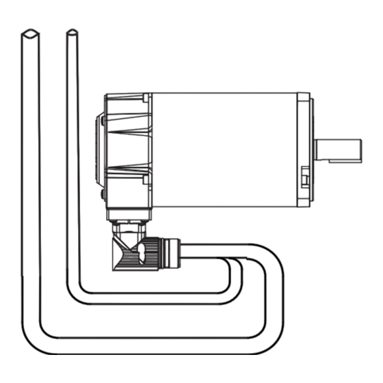
- Page 12 12 MP-Series Low-inertia Servo Motor with 100 mm to 165 mm Frame Size 4. Carefully align the flat surface on the feedback or the power/brake cable plug (shown in the diagram) with the flat surface on the motor connector. IMPORTANT The motor orientation shown is used to clearly show the alignment marker on each cable socket.
-
Page 13: Motor With Atex Rating Installations
MP-Series Low-inertia Servo Motor with 100 mm to 165 mm Frame Size 13 Motor with ATEX Rating Installations If your motor has an ATEX rating for hazardous environments, complete the following step. The catalog number on ATEX motor nameplates ends with H, for example MPL-xxxx-xxxxxH. Verify the continuity and functionality of the thermal switch signals, TS+ and TS-, transmitted through the feedback cable that connects the motor to its controlling drive. - Page 14 14 MP-Series Low-inertia Servo Motor with 100 mm to 165 mm Frame Size Rockwell Automation Publication MP-IN001I-EN-P - January 2015...
- Page 15 MP-Series Low-inertia Servo Motor with 100 mm to 165 mm Frame Size 15 Rockwell Automation Publication MP-IN001I-EN-P - January 2015...
- Page 16 16 MP-Series Low-inertia Servo Motor with 100 mm to 165 mm Frame Size Rockwell Automation Publication MP-IN001I-EN-P - January 2015...
- Page 17 MP-Series Low-inertia Servo Motor with 100 mm to 165 mm Frame Size 17 Rockwell Automation Publication MP-IN001I-EN-P - January 2015...
-
Page 18: Motor Load Force Ratings
18 MP-Series Low-inertia Servo Motor with 100 mm to 165 mm Frame Size Motor Load Force Ratings Motors are capable of operating with a sustained shaft load. The radial and axial load force location is shown in the figure, and maximum values are in the tables. Load Forces on Shaft Radial load force applied at center of shaft extension. - Page 19 MP-Series Low-inertia Servo Motor with 100 mm to 165 mm Frame Size 19 Axial Load Force Ratings (maximum radial load) Motor 500 rpm 1000 rpm 2000 rpm 3000 rpm 3500 rpm 4000 rpm 5000 rpm Cat. No. (lb) (lb) (lb) (lb) (lb) (lb)
-
Page 20: Connector Data
20 MP-Series Low-inertia Servo Motor with 100 mm to 165 mm Frame Size Connector Data These tables provide the signal descriptions for the feedback, power, and brake pinouts on the connectors. MPL-xxxxx-xx2xxx Connector Pin Descriptions Feedback Connector Power Connector High Resolution Encoder for: Signal 2000-line 2-pole... - Page 21 MP-Series Low-inertia Servo Motor with 100 mm to 165 mm Frame Size 21 MPL-xxxxx-xx7xxx Connector Pin Descriptions High Resolution High Resolution Incremental Encoder MPL-Axxx and Encoder Encoder MPL-Bxxx MPL-Axxx (230V) MPL-Bxxx (460V) MPL-A/Bxxxx-Hxxxx SIN+ SIN+ Phase U SIN- SIN- Phase V COS+ COS+ Phase W...
-
Page 22: Remove And Install A Shaft Key
22 MP-Series Low-inertia Servo Motor with 100 mm to 165 mm Frame Size Remove and Install a Shaft Key Shaft keys are constructed of steel. The specified tolerance provides an interference fit (slightly larger than the opening) for a secure and rigid connection. ATTENTION: Do not strike the motor’s shaft, couplings, or pulleys with tools during installation or removal of the shaft key. -
Page 23: Motor Cables And Accessory Kits
3 months, not to exceed 12 months, depending on use. Catalog numbers for the motors and corresponding replacement Nitrile–shaft–seal kits are listed in the table. Motor Cat. No. Shaft Seal Kit Cat. No. MPL-A310, MPL-B310 MPL-A320, MPL-B320 MPL-SSN-A3B3 MPL-A330, MPL-B330 MPL-A420, MPL-B420... -
Page 24: Specifications
24 MP-Series Low-inertia Servo Motor with 100 mm to 165 mm Frame Size Specifications Attribute Value Temperature, operating 0…40 °C (32…104 °F) Temperature, storage -30…70 °C (-22…158 °F) Relative humidity, storage 5…95% noncondensing Atmosphere, storage Noncorrosive IP66 (dust tight, powerful water jets, room IP Rating of motor with optional shaft seal installed... -
Page 25: Additional Resources
Declarations of Conformity (DOC) for Rockwell http://www.rockwellautomation.com/products/certification/ Automation products. You can view or download publications at http://www.rockwellautomation.com/literature/. To order paper copies of technical documentation, contact your local Allen-Bradley distributor or Rockwell Automation sales representative. Rockwell Automation Publication MP-IN001I-EN-P - January 2015... -
Page 26: Rockwell Automation Support
Rockwell Automation maintains current product environmental information on its website at http://www.rockwellautomation.com/rockwellautomation/about-us/sustainability-ethics/product-environmental-compliance.page. Allen-Bradley, Rockwell Software, MP-Series, Kinetix, and Rockwell Automation are trademarks of Rockwell Automation, Inc. Trademarks not belonging to Rockwell Automation are property of their respective companies. Rockwell Otomasyon Ticaret A.Ş., Kar Plaza İş Merkezi E Blok Kat:6 34752 İçerenköy, İstanbul, Tel: +90 (216) 5698400...
Need help?
Do you have a question about the MPL-A310 and is the answer not in the manual?
Questions and answers