Table of Contents
Advertisement
Quick Links
Vibration Monitoring and Predictive Maintenance
Solutions Kit Quick Start Guide (MultiHop)
Overview
The MultiHop version of the Vibration Solutions Kit provides visual status of up to 40 Banner vibration and temperature sensors that
are wirelessly linked to the included DXM Wireless Controller. The added benefits of a MultiHop style Solutions Kit include longer
range capabilities by using repeater radios, wiring multiple sensors to a single radio, and more vibration information available per
sensor for advanced applications.
The program takes a data sample every five minutes from the vibration sensors and the software uses the raw data to detect
whether an asset is running, create a baseline of the four vibration characteristics (RMS Velocity 10-1000 Hz on Z and X axis and
RMS High Frequency Acceleration 1000-4000 Hz on Z and X axis), and generate warning and alarm thresholds for those
characteristics. Only data from an operational asset is used to create the baselines or thresholds and only that data is used to trigger
warnings or alarms. Data from assets that are not running/operational appear on the graphs but are not used in the analysis.
RMS Velocity identifies asset imbalance, misalignment, looseness, and other low frequency machine issues.
RMS High Frequency Acceleration is used to indicate early bearing wear issues.
Hardware
Solutions Kit Model
SolutionsKit9-Vibe-MH
SolutionsKit9-Vibemetric-MH
SolutionsKit2-Vibe-MH
SolutionsKit2-Vibemetric-MH
This kit also requires a 24 V DC Class 2 (UL) or a Limited Power Source (LPS) (CE) power supply that is sold separately. Banner
recommends model PSW-24-1 (FCC/CE) or model PSD-24-4 (FCC/CE) if you are powering additional indicator lights.
Getting Started
1. Connect and plug in the 24 V DC Class 2 or LPS power supply to the Solutions Kit to apply power to the radios.
2. Assign sensor Modbus IDs (see
3. Bind the radios to the kit (see
4. Perform a site survey to confirm your signal quality (see
5. After a radio is bound with a sensor attached, the system begins sampling data to create a baseline for that sensor.
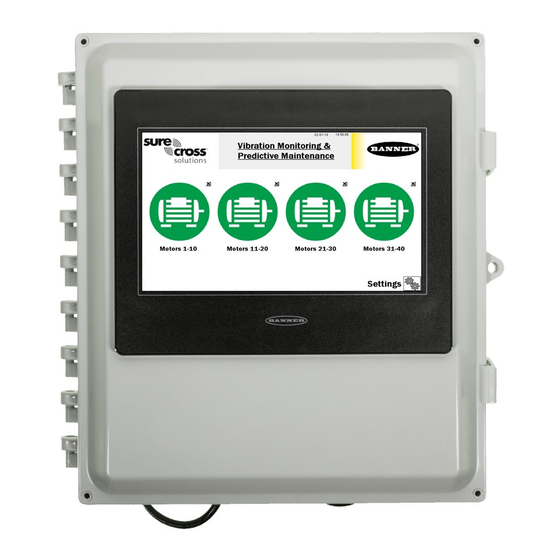
HMI Home Screen
Status icons represent groups of 10 assets for a total of 40 motors. Each icon is a color-coded indication of the status of vibration
warnings (yellow) or alarms (red), temperature warnings or alarms, wireless connection status (green), or out of sync (orange) within
that group.
The icon acts as a touch button that brings up the 10 individual icons that represent that assets' status and acts as a touch button to
view that assets' screen where detailed data viewing options are available (see
Original Document
214301 Rev. F
Units of
Radio Frequency
Measure
900 MHz
Imperial
900 MHz
Metric
2.4 GHz
Imperial
2.4 GHz
Metric
Assign Modbus IDs to the Sensors
Bind a Node
on page 3).
21 July 2022
Contents
10" Banner Touch Screen HMI with Ethernet connection
DXM700-B1R4 Wireless Controller
5-port Ethernet switch
14" x 12" Polycarbonate enclosure
M12 power input connector
on page 2).
Perform a Site Survey
on page 3).
Vibration Node Group Screens
DXM700-B1R2 or
, DIN rails, and terminal blocks
on page 3).
214301
Advertisement
Table of Contents

Related Manuals for Banner SolutionsKit9-Vibe-MH


Summary of Contents for Banner SolutionsKit9-Vibe-MH
- Page 1 Metric This kit also requires a 24 V DC Class 2 (UL) or a Limited Power Source (LPS) (CE) power supply that is sold separately. Banner recommends model PSW-24-1 (FCC/CE) or model PSD-24-4 (FCC/CE) if you are powering additional indicator lights.
- Page 2 Site Survey and Binding Screen Banner Wireless radios, such as the battery-powered H10 radio paired with VT1 Vibration and Temperature Sensors or any Banner MultiHop Radio with RS485 connected to VT2 Vibration and Temperature Sensors, must be bound to the DXM Wireless Controller inside the Solutions Kit to begin communicating.
-
Page 3: Perform A Site Survey
Vibration Monitoring and Predictive Maintenance Solutions Kit Quick Start Guide (MultiHop) Use the site survey function to measure the signal strength of radios after the solutions kit and radios are installed. Line-powered radios can be used as repeaters to improve signal connection between other nearby radios and the master radio inside the solutions kit. - Page 4 Vibration Monitoring and Predictive Maintenance Solutions Kit Quick Start Guide (MultiHop) Touch any icon to bring up the individual sensor's screen that includes graphs, raw data, and alert descriptions (see Individual Radio (Asset) Status Screen on page 4). Touch X (upper right hand corner of each icon) to hide that asset and prevent connection status alerts from that senspr/radio from appearing on the main HMI screen.
-
Page 5: Settings Screen
Directly to the right of the button is the raw current reading in Amps of the selected Node. The readout color is white if it’s normal, yellow if it’s in a warning state, and red if it’s in an alarm state. Requires the use of the Banner CM1L Condition Monitoring VT/CT node. - Page 6 Vibration Monitoring and Predictive Maintenance Solutions Kit Quick Start Guide (MultiHop) Acute Alarm Samples The default number of samples above the warning or alarm threshold before an alert is triggered is five consecutive samples. Use the numeric entry box to adjust the default value up or down. Asset Baselining Sensors bound into the system automatically begin baselining.
- Page 7 Vibration Monitoring and Predictive Maintenance Solutions Kit Quick Start Guide (MultiHop) 1. Turn on baselining for the appropriate Nodes if a new baseline needs to be generated. The initial baseline is generated any time a new sensor is connected to the system (or bound to the controller radio) and begins sending data without the need to trigger these switches.
-
Page 8: Advanced Options
Vibration Monitoring and Predictive Maintenance Solutions Kit Quick Start Guide (MultiHop) Auto Delete Files Older than ‘X’ Days The HMI auto deletes files older than the selected number of days. Default is 30 days with a maximum of 45 days for MulitHop radio kits and 60 days for Performance radio kits. Copy Log Files to USB Drive Plug a USB drive into the back of the HMI and click here to select the log files or folders to copy. -
Page 9: Additional Vibration Information
Vibration Monitoring and Predictive Maintenance Solutions Kit Quick Start Guide (MultiHop) Additional Vibration Information The vibration solutions kit provides machine learning for baseline and alerting on RMS Velocity and High Frequency Acceleration for both the X and Z Axis. For each of these register tables, S is the sensor ID number (between 1 and 40). However, the vibration sensor contains many additional registers of vibration information that are stored in the local registers and can be polled by any host connected to the same network or the data can be sent to the cloud. - Page 10 Alarms screen. For more information on creating accounts on and using the Banner Cloud Data Services (CDS) system, please refer to the Banner CDS Quick Start Guide (p/n 201126) or the Instruction Manual (p/n 178337).
- Page 11 Vibration Monitoring and Predictive Maintenance Solutions Kit Quick Start Guide (MultiHop) Create a New Gateway After you log into the Banner Cloud Data Services website, the Gateway screen displays. Follow these steps to create a new monitoring site. 1. Click on +New Gateway.
- Page 12 Vibration Monitoring and Predictive Maintenance Solutions Kit Quick Start Guide (MultiHop) Configure the DXM to Push Information to the Cloud 1. Within the DXM Configuration Software, go to the Settings > Cloud Services screen. 2. Set the Server name/IP to push.bannercds.net. 3.
- Page 13 To access a Demo version of the website, contact your local Banner distributor and follow the instructions in the technical note Connecting DXM Wireless Controller to Banner Web Services Demo Site for modified instructions on how to send data to the Demo site.
-
Page 14: Specifications
Banner Engineering Corp. warrants its products to be free from defects in material and workmanship for one year following the date of shipment. Banner Engineering Corp. will repair or replace, free of charge, any product of its manufacture which, at the time it is returned to the factory, is found to have been defective during the warranty period. - Page 15 Banner es una marca registrada de Banner Engineering Corp. y podrán ser utilizadas de manera indistinta para referirse al fabricante. "Este equipo ha sido diseñado para operar con las antenas tipo Omnidireccional para una ganancia máxima de antena de 6 dBd y Yagi para una ganancia máxima de antena 10 dBd que en seguida se enlistan.
Need help?
Do you have a question about the SolutionsKit9-Vibe-MH and is the answer not in the manual?
Questions and answers