Emerson FB3000 Instruction Manual
Remote terminal unit
Hide thumbs
Also See for FB3000:
- Instruction manual (132 pages) ,
- Safe use instructions (51 pages) ,
- User manual (44 pages)

Related Manuals for Emerson FB3000


Summary of Contents for Emerson FB3000
- Page 1 Emerson FB3000 RTU Instruction Manual D301851X012 October 2022 Emerson FB3000 Remote Terminal Unit (RTU) Instruction Manual Energy and Transportation Solutions...
- Page 2 Emerson office. You can also receive the same quality training via our live, interactive Emerson Virtual Classroom and save on travel costs. For our complete schedule and further information, contact the Energy and Transportation Solutions Training Department at 800-338-8158 or email us at education@emerson.com.
-
Page 3: Power
CSA Approval Information SAFETY FIRST Read this document carefully before installing an Emerson FB3000 RTU. Refer to the other sections of the instruction manual for general information. In the event of a conflict between the other sections of this manual and this document, always follow the instructions in this document. - Page 4 1.0 g for 10 to 150 Hz for 30 minutes; 0.5 g for 150 to 2000 Hz for 30 minutes Locations: The Emerson FB3000 Remote Terminal Unit (RTU) is listed by the Canadian Standards Association (CSA) as suitable for use in Class I, Division 2, Groups A, B, C and...
-
Page 5: Personality Module
When using DIN-rail mounting as the method of installation for the extended backplane configuration, use DIN-rail end brackets at the two ends of the extended backplane to prevent side movements of the equipment on the DIN-rail. Refer to the Emerson FB3000 RTU Instruction Manual (D301851X012) for details. - Page 6 FB3000 - CSA Approval Information CD9411M Issued: June 23, 2022 ANSI/UL 121201 Non-incendive Electrical Equipment for Use in Class I and II Division 2 and Class III Division 1 and 2 Hazardous Locations. CAN/CSA —C22.2 No. 60079-7 Explosive atmospheres — Part 7: Equipment protection by increased safety “e”...
- Page 7 FB3000 - CSA Approval Information CD9411M Issued: June 23, 2022 CSA-5...
-
Page 9: Table Of Contents
Emerson FB3000 RTU Instruction Manual D301851X012 October 2022 Contents Chapter 1. Introduction Safety Labels ......................... 2 Features ..........................2 FB3000 RTU Chassis ......................3 Central Processing Unit (CPU) ....................3 ... -
Page 10: Service
Emerson FB3000 RTU Instruction Manual D301851X012 October 2022 3.1.4 Digital Outputs (3MIX12/3MSG12) ................. 43 3.1.5 Pulse Inputs (3MIX12/3MSG12) ................48 ® HART Input/Output Channels (3HRT04/3HRTSG4/HRT04) ..........49 3.2.1 Point-to-Point Mode ....................50 ... -
Page 11: Chapter 1. Introduction
You can also purchase the FB3000 as an I/O-only device (FBxRemote I/O™) where control runs in a separate host FB3000 RTU. This manual describes how to install and configure the FB3000 hardware. -
Page 12: Safety Labels
Observe all precautionary signs posted on the equipment. Failure to do so may result in death or serious injury to personnel. Features The FB3000 RTU includes the following key features: Operates in Class I Division 2 non-incendive and Ex ec Zone 2 non-sparking environments when ... -
Page 13: Fb3000 Rtu Chassis
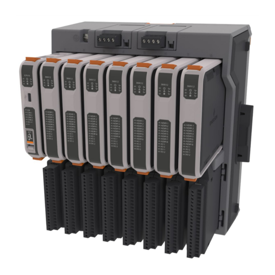
Provides Micro A-B USB connector to support DNP3 communications. FB3000 RTU Chassis The FB3000 RTU has either a four-slot or an eight-slot chassis. The CPU is always in slot one of the base chassis. Figure 1-2. Chassis – 8 Slot Version (with/without slot covers) Each slot includes an upper section and a lower section. -
Page 14: Memory
Emerson FB3000 RTU Instruction Manual D301851X012 October 2022 Memory The RTU includes both static and flash memory. Table 1-1. Memory Memory Usage 256 MB Flash Firmware image and report files; with 104 MB reserved for file system and 128 MB available for database and history... -
Page 15: Power
Emerson FB3000 RTU Instruction Manual D301851X012 October 2022 Power You power the RTU using an external DC input. The 8-slot chassis includes two power supply modules; the 4-slot chassis includes a single power supply module. Table 1-2. Power Power Source... -
Page 16: Software Tools
VPN and firewall security. Recommended solutions include the MOXA EDR‐810, the Hirschman Eagle One, or the Phoenix mGuard rs4000 (or equivalents). An example of how to install one of these devices to the RTU can be found in the Emerson Energy and Transportation Solutions ®... -
Page 17: Chapter 2. Installation
Connecting Communications Ports Hazardous Locations For North America the FB3000 has certifications for Class I Division 2 (Groups A, B, C & D) non- incendive and non-hazardous locations only. For other world areas the FB3000-has ATEX and IEC Ex certifications for Ex ec Zone 2 non-sparking installations and non-hazardous locations only. his is body text. -
Page 18: Site Considerations
The RTU must reside in an accessible location for configuration and service. Refer to the dimensional drawings for information on the space required. Figure 2-1. FB3000 Dimensions – 8 Slot (with/without DIN Rail mounting plate assembly No DIN mounting plates in this view... - Page 19 Emerson FB3000 RTU Instruction Manual D301851X012 October 2022 Figure 2-2. FB3000 Dimensions – 4 slot (with/without DIN rail mounting plate assembly) No DIN mounting plate in this view Installation...
-
Page 20: Connecting Extension Chassis
The FB3000 base chassis cannot support an extension chassis using the left- hand connector. The FB3000 4-slot chassis can serve as a single base chassis, or as the last extension chassis in an 8- slot chassis assembly. The FB3000 4-slot chassis cannot have an extension chassis since it has no right-hand connector. - Page 21 Emerson FB3000 RTU Instruction Manual D301851X012 October 2022 Figure 2-3. Removing Chassis Connector Cover Press the two chassis together. If mounting on a DIN rail, slide both chassis onto the DIN rail first to ensure proper alignment and place clamps/brackets at both ends of assembly on DIN rail to ensure side connectors between chassis remain fully engaged.
-
Page 22: General Wiring Guidelines
When using shielded cable, ground all shields at a suitable Instrument Earth connection point. This prevents circulating ground current loops that can cause signal errors. See the FB3000 product data sheet for information about applicable standards for EMI and RFI emissions and susceptibility. -
Page 23: Grounding
October 2022 Grounding There are four separate and distinct ground references within the FB3000 architecture. The chassis ground lug (also known as Protective Earth or PE), internal system bus ground, isolated ground, and the 24V loop ground (for modules that support loop power). -
Page 24: Internal System Bus Ground
Emerson FB3000 RTU Instruction Manual D301851X012 October 2022 2.5.2 Internal System Bus Ground The internal system bus ground provides an internal reference to system power negative or ground input. Users cannot access this ground. 2.5.3 Isolated Ground on 3MIX12/3MSG12 Module The 12-channel mixed I/O module includes an isolated ground system (ISO_GND) on pins 5, 10, 12, and 14 of TB1. -
Page 25: 24V Loop Ground On 3Mix12/3Msg12 Module
Emerson FB3000 RTU Instruction Manual D301851X012 October 2022 2.5.4 24V Loop Ground on 3MIX12/3MSG12 Module Pin 20 on TB1 of the 12-channel mixed I/O module serves as the return side of the +24V loop power supply. It is completely isolated from the other three ground systems his is body text. - Page 26 Note As previously noted, when mounting an FB3000 with one or more extension chassis in an enclosure, ensure that you mount the racks in a left to right horizontal direction (wall mount on DIN-rails) inside the end user system enclosure to allow for adequate heat dissipation.
-
Page 27: Panel Or Wall Mounting The Chassis
Emerson FB3000 RTU Instruction Manual D301851X012 October 2022 Figure 2-10. Single 4-Slot Chassis only can be Mounted Horizontally or Vertically 2.6.1 Panel or Wall Mounting the Chassis To mount the RTU directly to a wall without using the DIN rail, you must first remove the mounting plate. - Page 28 Emerson FB3000 RTU Instruction Manual D301851X012 October 2022 Figure 2-11. Panel or Wall Mounting Screw Locations 8-Slot Chassis Left, 4-Slot Chassis Right 4. Slide the mounting plate off the chassis. Figure 2-12. Sliding Off the Mounting Plate 5. Insert longer screws (screw length depends on the wall/panel) in the holes shown in Figure 2-11 to mount the device to a wall or panel.
- Page 29 Emerson FB3000 RTU Instruction Manual D301851X012 October 2022 Figure 2-13. Screw holes – From Back (8-Slot Chassis) Installation...
-
Page 30: Removing Battery Saver Tabs
Emerson FB3000 RTU Instruction Manual D301851X012 October 2022 Figure 2-14. Screw Holes – From Back (4-Slot Chassis) Removing Battery Saver Tabs When you are ready to install the RTU and place it into operation, you must remove the battery saver tabs for the SRAM coin cell batteries. Each power module, as well as the CPU battery, has a similar tab. -
Page 31: Connecting Power
Emerson FB3000 RTU Instruction Manual D301851X012 October 2022 Connecting Power Power comes from an external power source. The device supports both 12V and 24V power supplies. It accepts DC voltage from 10.5 to 30V; the amount of power required varies depending upon the options used. -
Page 32: Power Planning
If your installation includes multiple chassis, wire power only to the left-most (base) chassis. Note ‐ If your FB3000 does not power on, check that the polarity of the DC input voltage wiring connections match Figure 2 16. If you accidentally reversed the polarity, it triggers an internal fuse and switch to protect the device from damage. -
Page 33: 24V Power
12V≤ V < 24V 10.5V≤ V < 12V The number of mixed I/O modules that can be supported by the FB3000 loop power connectors varies depending upon the RTU’s external power supply. For example, if you have a 12V installation, you can see by referring to... -
Page 34: Removing/Replacing The I/O Cover
Emerson FB3000 RTU Instruction Manual D301851X012 October 2022 Removing/Replacing the I/O Cover DANGER EXPLOSION HAZARD - MAY CAUSE DEATH Ensure the area in which you perform this operation is non-hazardous. Performing this operation in a hazardous area could result in an explosion. - Page 35 Emerson FB3000 RTU Instruction Manual D301851X012 October 2022 Port RS-232 4-Wire RS-485 2-Wire RS-485 COM2 TXD2 TX2+ TX2+ RTS2 TX2– TX2– RXD2 RX2+ CTS2 RX2– COM3 (Isolated RS-485 only) T3– (ISO GND) TX/RX+3 TX/RX3– COM4 (Isolated RS-485 only) T4– (ISO GND) TX/RX4+ TX/RX4–...
-
Page 36: Connecting To Com1
Emerson FB3000 RTU Instruction Manual D301851X012 October 2022 2.10.1 Connecting to COM1 Using the CPU personality module, you can configure the COM1 port as RS-232, RS-485 (4-wire), or RS-485 (2-wire) communications. When connecting COM1 to another device using RS-232, use a cable with configurations as shown... - Page 37 Emerson FB3000 RTU Instruction Manual D301851X012 October 2022 When connecting COM1 to another device using RS-485 (4-wire), use a cable with configurations Figure 2-21 as shown in Figure 2-21. COM1 Configured as RS-485 (4-wire) RS-485 (4-wire) port on device Connect cable shields to suitable Instrument Earth connection point...
- Page 38 Emerson FB3000 RTU Instruction Manual D301851X012 October 2022 When connecting COM1 to another device using RS-485 (2-wire), use a cable with configurations as shown in Figure 2-22: Figure 2-22. COM1 Configured as RS-485 (2-wire) RS-485 (2-wire) port on device Connect cable shields to suitable Instrument Earth connection point Regardless of the interface standard –...
-
Page 39: Connecting To Com2
Emerson FB3000 RTU Instruction Manual D301851X012 October 2022 2.10.2 Connecting to COM2 Using the CPU personality module, you can configure the COM2 port as RS-232, RS-485 (4-wire), or RS-485 (2-wire) communications. When connecting COM2 to an RS-232 port on another device (a PC or another controller/RTU) use... - Page 40 Emerson FB3000 RTU Instruction Manual D301851X012 October 2022 When connecting COM2 to an RS-485 (4-wire) port on another device use a cable with configurations as shown in Figure 2-24: Figure 2-24. COM2 Configured as RS-485 (4-wire) RS-485 (4-wire) port on device...
- Page 41 Emerson FB3000 RTU Instruction Manual D301851X012 October 2022 When connecting COM2 to an RS-485 (2-wire) port on another device use a cable with configurations as shown in Figure 2-25: Figure 2-25. COM2 Configured as RS-485 (2-wire) RS-485 (2-wire) port on device Connect cable shields to suitable Instrument Earth connection point Regardless of the interface standard –...
-
Page 42: Connecting To Com3
Emerson FB3000 RTU Instruction Manual D301851X012 October 2022 2.10.3 Connecting to COM3 COM3 can be configured for RS-485 (2-wire) communication. When connecting COM3 to an RS- 485 port on another device (such as a Rosemount 4088B transmitter), use a cable with... - Page 43 RS-485 bus; twisted pair required Up to ten 4088B transmitters allowed per port; FB3000 only provides power for a maximum of four transmitters. Any other transmitters require an external power supply. When communicating with more than six 4088Bs at 9600 baud, update times exceed once a second.
-
Page 44: Connecting To Com4
Emerson FB3000 RTU Instruction Manual D301851X012 October 2022 2.10.4 Connecting to COM4 You can configure COM4 for RS-485 (2-wire) communication. When connecting COM4 to an RS- 485 port on another device (such as a Rosemount 4088B transmitter), use a cable with configurations as shown below. - Page 45 Enable AC termination using switches on last multi-dropped 4088B transmitter RS-485 bus; twisted pair required Up to ten 4088B transmitters allowed per port; FB3000 only provides power for a maximum of four transmitters. Any other transmitters require an external power supply.
-
Page 46: Ethernet And Micro Usb Port
Emerson FB3000 RTU Instruction Manual D301851X012 October 2022 2.10.5 Ethernet and Micro USB Port Located on the top of the CPU logic module, the two Ethernet ports are standard 8-pin 10/100Base-T RJ -45 8P8C sockets. Connect to an Ethernet switch using the appropriate Category 5 shielded patch cable. -
Page 47: Chapter 3. I/O Configuration And Wiring
8-Channel Output Module Configuration (3AODO8/3OTSG8/OUT08) I/O in the FB3000 RTU comes from I/O modules installed in the I/O slots. The upper bay holds the “logic” module. All wiring is made to the lower bay “personality” modules. DANGER EXPLOSION HAZARD - MAY CAUSE DEATH Connect or disconnect only in a non-hazardous area. -
Page 48: Analog Inputs (3Mix12/3Msg12)
Emerson FB3000 RTU Instruction Manual D301851X012 October 2022 3.1.1 Analog Inputs (3MIX12/3MSG12) The 12-channel mixed I/O module includes eight channels you can individually configure as either analog inputs (AI), digital inputs (DI) or pulse inputs (PI). Note No external resistor is required to interface with a current (4-20 mA) device. To convert a current to a voltage to be read by the hardware analog to digital converter, when you configure the AI for current within FBxConnect, the device enables a 250 ohm resistor across the channel input. - Page 49 Emerson FB3000 RTU Instruction Manual D301851X012 October 2022 Figure 3-1. Analog Input (AI) Wiring Using 1-5VDC or 4-20mA External voltage source External current source Power Supply 30VDC Max Alternatively, you can use loop power as shown in Figure 3-2. In the figure, AIDIPI_08 is shown connected to an external current source.
-
Page 50: Analog Outputs (3Mix12/3Msg12)
Emerson FB3000 RTU Instruction Manual D301851X012 October 2022 Figure 3-2. Analog Input (AI) Wiring Using Loop Power External current source 3.1.2 Analog Outputs (3MIX12/3MSG12) The 12-channel mixed I/O module includes two dedicated analog output channels, with the following characteristics: Table 3-3. Analog Output Characteristics... - Page 51 Emerson FB3000 RTU Instruction Manual D301851X012 October 2022 voltage output mode and is shown connected to an external voltage field device. AO_1 connects to the common ISO_GND using pin 12; AO_2 connects to the common ISO_GND using pin 14. Figure 3-3. Analog Output (AO) Wiring Both AO channels are read back to check the health of the AO: Current outputs with loads are verified to be within the operating range of the output.
-
Page 52: Digital Inputs (3Mix12/3Msg12)
Emerson FB3000 RTU Instruction Manual D301851X012 October 2022 3.1.3 Digital Inputs (3MIX12/3MSG12) The 12-channel mixed I/O module includes eight channels you can individually configure as either analog inputs (AI), digital inputs (DI) or pulse inputs (PI). When configured as digital inputs, the channels have the following characteristics: Table 3-4. -
Page 53: Digital Outputs (3Mix12/3Msg12)
Emerson FB3000 RTU Instruction Manual D301851X012 October 2022 Figure 3-4 shows how to wire the digital input. In the figure, AIDIPI_6 is shown configured as a digital input. ISO_GND (pin 10) is the ground connection for AIDIPI_6. Figure 3-4. Digital Input (DI) Wiring (internal pull-up enabled) 3.1.4... -
Page 54: Digital Output Characteristics
Emerson FB3000 RTU Instruction Manual D301851X012 October 2022 Table 3-5. Digital Output Characteristics Type Number Characteristics Supported Contact closure by solid state relay Digital 2 dedicated Maximum current of 500mA at 31VDC Output (DO) channels Can be configured to fail at last output value or fail to a fault state. - Page 55 Emerson FB3000 RTU Instruction Manual D301851X012 October 2022 Figure 3-5 shows typical wiring with low-side switch (LSS) enabled for DO1 and DO2. You enable the low side switch for either or both DOs in FBxConnect. Figure 3-5. Digital Output (DO) Wiring – Low Side Switch (LSS) Enabled...
- Page 56 Emerson FB3000 RTU Instruction Manual D301851X012 October 2022 Figure 3-6 shows typical DO wiring using the internal loop power output. Note The maximum load for the loop power output is 200 mA. Figure 3--6 Digital Output (DO) Wiring using the internal Loop Power Output...
- Page 57 Emerson FB3000 RTU Instruction Manual D301851X012 October 2022 Figure 3-7 shows how to wire a digital output as a dry contact closure. Figure 3--7. Digital Output (DO) Wiring – Dry Contact Closure 500 mA load max field device 30VDC Max Power Supply...
-
Page 58: Pulse Inputs (3Mix12/3Msg12)
Emerson FB3000 RTU Instruction Manual D301851X012 October 2022 Figure 3-8 shows how to wire a digital output as a contact closure using the internal 24V loop supply. The total current for all devices connected to a DO channel must not exceed 500 mA. For example, you could wire two devices in parallel, one with 200 mA, and another with 300 mA. -
Page 59: Hart ® Input/Output Channels (3Hrt04/3Hrtsg4/Hrt04)
® (Highway Addressable Remote Transducer) module. This allows the FB3000 to communicate with external HART devices such as transmitters. Insert the 3HRT04 module in any base chassis slot except slot 1 and insert its corresponding 3HTSG4 module below it. The 3HRT04/3HTSG4 modules cannot be used in an extension chassis. -
Page 60: Point-To-Point Mode
Emerson FB3000 RTU Instruction Manual D301851X012 October 2022 You can configure a channel for point-to-point operation in which case it communicates with a single HART device. Alternatively, you can configure a channel for multi-drop operation in which it communicates with up to five (5) HART devices in parallel. - Page 61 Emerson FB3000 RTU Instruction Manual D301851X012 October 2022 Figure 3-10 shows how to wire all four HART channels in point-to-point mode. In this case, each HART channel only communicates to a single HART device. You choose whether a given channel serves as an input or output in FBxConnect.
-
Page 62: Multi-Drop Mode
Emerson FB3000 RTU Instruction Manual D301851X012 October 2022 3.2.2 Multi-Drop Mode In multi-drop mode, only the HART digital signaling (FSK – Frequency Shift Keying) is present and 4-20mA analog current signal is permitted (no AO allowed). Each device can support a maximum 4mA bias current. - Page 63 Emerson FB3000 RTU Instruction Manual D301851X012 October 2022 Figure 3-13 shows how to wire a HART channel for multi-drop mode with power from an external supply. Multi-drop mode only supports inputs, you cannot have multi-drop outputs. Figure 3-13. HART Wiring – Multi-Drop Mode on Channel 1 – External Supply...
-
Page 64: Analog Input Mode (Hart Communication Disabled)
Emerson FB3000 RTU Instruction Manual D301851X012 October 2022 3.2.3 Analog Input Mode (HART Communication Disabled) If you have an unused HART channel, you can use it as a 4-20mA analog input (AI current mode). In FBxConnect, you must Enable the 250-Ohm Termination Resistor and set the HART Comm Mode to Disabled. -
Page 65: Analog Output Mode (Hart Communication Disabled)
Emerson FB3000 RTU Instruction Manual D301851X012 October 2022 3.2.4 Analog Output Mode (HART Communication Disabled) If you have an unused HART channel, you can use it as a 4-20mA current sinking analog output. In FBxConnect, you must Disable the 250 Ohm Termination Resistor and set the HART Comm Mode to Disabled. - Page 66 Emerson FB3000 RTU Instruction Manual D301851X012 October 2022 2. Select the HART channel you want to configure; there are four HART channels per module. 3. If this channel is an analog input, click the Configuration tab to configure the AI.
-
Page 67: 8-Channel Output Module Configuration (3Aodo8/3Otsg8/Out08)
D301851X012 October 2022 8-Channel Output Module Configuration (3AODO8/3OTSG8/OUT08) The FB3000 supports an 8-channel output module. Each channel can be individually configured as either an analog output or a digital output. 3.3.1 Analog Outputs (3AODO8/3OTSG8/OUT08) On the 8-channel output module, when a channel is configured as an analog output, it has the following characteristics: Table 3-8. - Page 68 Emerson FB3000 RTU Instruction Manual D301851X012 October 2022 Figure 3-16 shows how to wire the analog output. In the figure, AO_4 is configured for current output mode and is shown connected to an external current field device. AO_7 is configured for voltage output mode and is shown connected to an external voltage field device.
-
Page 69: Digital Outputs (3Aodo8/3Otsg8/Out08)
Emerson FB3000 RTU Instruction Manual D301851X012 October 2022 3.3.2 Digital Outputs (3AODO8/3OTSG8/OUT08) When a channel on the 8-channel output module is configured as a digital output, it has the following characteristics: Internally, the DO acts as a simple contact closure. When 1 (ON) the contact closes, when 0 ... - Page 70 Emerson FB3000 RTU Instruction Manual D301851X012 October 2022 Figure 3-17 shows how to wire a digital output (DO_02) to drive an inductive load (such as a relay coil). Figure 3-17. Digital Output (DO) Wiring Suppression Diode Relay coil or inductive load...
-
Page 71: Chapter 4. Operation
DNP3 Protocol Specifications Manual (for Emerson FB3000 RTUs) (D301858X012) FBxConnect Configuration Software User Manual (for the FB3000 RTU) (D301882X012) Provide the SCADA host with information about the various parameters it needs to extract from the application running in the RTU. Typically, the SCADA host software includes a utility that allows you to identify this information so it can be incorporated into the database at the SCADA host. -
Page 72: Communicating With A Laptop Using A Serial Port
Emerson FB3000 RTU Instruction Manual D301851X012 October 2022 Using whatever human-machine interface (HMI) tools exist for the SCADA host, create graphical displays or reports that include the parameters from the application required for successful operator interaction (setpoints, flow variables and so on). -
Page 73: Maintaining Backups
Emerson FB3000 RTU Instruction Manual D301851X012 October 2022 Maintaining Backups Important To be prepared in case of disaster (flood, lightning strike, etc.), we strongly recommend you maintain backups of your configuration, data, and applications. Maintaining current backups is a key part of successful disaster recovery. Anytime you modify the configuration or applications/solutions, you should perform a new backup. - Page 74 Emerson FB3000 RTU Instruction Manual D301851X012 October 2022 Operation...
-
Page 75: Chapter 5. Service And Troubleshooting
Emerson-authorized repair facility. Important Only use batteries supplied with the RTU or sold by Emerson Remote Energy and Transportation Solutions as spare parts for this RTU. If you substitute a battery you obtain elsewhere you will void your hazardous location certification unless it is the identical part from the same manufacturer as that supplied with the RTU from Emerson. -
Page 76: Returning The Unit For Repairs
Other types of repairs cannot be performed in the field. In those cases, you must ship the unit to an Emerson-authorized repair facility. Contact Emerson Remote Automation Solutions for a return authorization number and instructions for where to ship the unit. -
Page 77: Interpreting The Status Leds
Emerson FB3000 RTU Instruction Manual D301851X012 October 2022 Interpreting the Status LEDs Each of the modules in the RTU includes status light-emitting diodes (LEDs). The meaning of each LED varies depending upon the color displayed or whether the LED flashes. - Page 78 Emerson FB3000 RTU Instruction Manual D301851X012 October 2022 Color/State Meaning COM1, COM2, GREEN Receive on this port in progress. COM3, COM4 Transmission on this port in progress. ORANGE Receive and transmit in progress. No transmissions active ISO+T GREEN RS-485 communications enabled on...
- Page 79 Emerson FB3000 RTU Instruction Manual D301851X012 October 2022 Color/State Meaning Flashing ORANGE Override and failure ORANGE Override Disabled DO1 and DO2 GREEN DO is on Flashing RED (Reserved) Failure Flashing ORANGE Override and failure ORANGE Override DO is off Special LED Sequence: Communication Status and Termination Status alternating flashing GREEN rapidly indicates power for the module has fallen to power trip point;...
- Page 80 Emerson FB3000 RTU Instruction Manual D301851X012 October 2022 Color/State Meaning Personality module missing or mismatched type YELLOW Firmware incompatibility between CPU and I/O module. Review release notes and Board Info in FBxConnect and upgrade or downgrade firmware so CPU and I/O module firmware revisions are compatible.
- Page 81 Emerson FB3000 RTU Instruction Manual D301851X012 October 2022 Table 5-4. LED Descriptions — 8-Channel Output Module Color/State Meaning Module Status GREEN Power good Failure No power Communication Flashing GREEN Message send to CPU in progress Status No communication with CPU...
-
Page 82: Removing/Replacing The Power Module
Emerson FB3000 RTU Instruction Manual D301851X012 October 2022 Removing/Replacing the Power Module DANGER EXPLOSION HAZARD - MAY CAUSE DEATH Ensure the area in which you perform this operation is non-hazardous. Performing this operation in a hazardous area could result in an explosion. -
Page 83: Removing/Replacing The Sram Batteries
Emerson FB3000 RTU Instruction Manual D301851X012 October 2022 Removing/Replacing the SRAM Batteries A 3V lithium coin cell battery in each of the two power supply modules provides backup power for the SRAM and the real time clock. These batteries operate continuously with a typical expected cumulative operation of 4900 hours if only one power module is installed, or 9800 hours if both power modules are installed. -
Page 84: Battery In Power Module
Emerson FB3000 RTU Instruction Manual D301851X012 October 2022 5.4.1 Battery in Power Module Remove the power module. 1. Grasp the battery and pull it out of the power module. 2. Safely dispose of the old battery according to local regulations. - Page 85 Backup data in the CPU (See Section 5.9 and Section 5.10). Remove power from the FB3000 (See Chapter Depress the orange tabs at the top and bottom of the CPU module to release the module and slide it straight out of the slot.
-
Page 86: Removing/Replacing An I/O Logic Module
Emerson FB3000 RTU Instruction Manual D301851X012 October 2022 Removing/Replacing an I/O Logic Module DANGER EXPLOSION HAZARD - MAY CAUSE DEATH Ensure the RTU is in a non-hazardous area. Never open the enclosure in a hazardous area. Performing this operation in a hazardous area could result in an explosion. -
Page 87: Removing/Replacing A Personality Module
Emerson FB3000 RTU Instruction Manual D301851X012 October 2022 Removing/Replacing a Personality Module DANGER EXPLOSION HAZARD - MAY CAUSE DEATH Ensure the RTU is in a non-hazardous area. Never open the enclosure in a hazardous area. Performing this operation in a hazardous area could result in an explosion. -
Page 88: Upgrading System Firmware
If this personality module is for an I/O module, wire I/O connections as described in Chapter Upgrading System Firmware Periodically Emerson releases new system firmware for the RTU to introduce new features or update system functions. You must know a valid username/password combination for the RTU to complete this process. - Page 89 Emerson FB3000 RTU Instruction Manual D301851X012 October 2022 Figure 5-12. Firmware Update dialog box Select the checkbox in the Selected column to choose the firmware. If you are downloading the same version that is already installed on the device, select Download selected packages even if they are unchanged.
- Page 91 1-1. FB3000 RTU ..........1 wiring ............... 32 1-2. Chassis — 8 Slot Version ....... 3 COM4 2-1. FB3000 Dimensions — 8 Slot ......8 wiring ............... 34 2-2. FB3000 Dimensions — 4 slot ......9 Communication 2-3. Removing Chassis Connector Cover ..11 establishing ............
- Page 92 3-14. HART Comm Disabled — Channel Wired as AI SRAM ..............4 ..............54 3-15. HART Comm Disabled — Channel Wired as AO ..............55 3-16. Analog Output (AO) Wiring ..... 58 3-17. Digital Output (DO) Wiring ...... 60 5-1. FB3000 RTU Components ......66 Index...
- Page 93 Emerson FB3000 RTU Instruction Manual D301851X012 October 2022 Micro USB Port ............36 2-5. COM Terminal Blocks ........ 24 Mounting the chassis ..........15 3-1. Supported I/O Modules ......37 3-2. Analog Input Characteristics (12-Channel Mixed I/O Module) ......... 38 3-3.
- Page 96 Emerson Automation Solutions, Emerson, and the Singapore 128461 Emerson logo are trademarks and service marks of Emerson Electric Co. All other marks are T +65 6777 8211| F +65 6777 0947 the property of their respective owners.
Need help?
Do you have a question about the FB3000 and is the answer not in the manual?
Questions and answers