Emerson FB3000 Instruction Manual
Remote terminal unit
Hide thumbs
Also See for FB3000:
- Instruction manual (132 pages) ,
- Safe use instructions (51 pages) ,
- User manual (44 pages)

Related Manuals for Emerson FB3000


Summary of Contents for Emerson FB3000
- Page 1 Emerson FB3000 RTU Instruction Manual D301851X012 May 2022 Emerson FB3000 Remote Terminal Unit (RTU) Instruction Manual Remote Automation Solutions...
- Page 2 Our full-time professional instructors can conduct classroom training at several of our corporate offices, at your site, or even at your regional Emerson office. You can also receive the same quality training via our live, interactive Emerson Virtual Classroom and save on travel costs. For our complete schedule and further information, contact the Remote Automation Solutions Training Department at 800-338-8158 or email us at education@emerson.com.
- Page 3 CSA Approval Information SAFETY FIRST Read this document carefully before installing an Emerson FB3000 RTU. Refer to the other sections of the instruction manual for general information. In the event of a conflict between the other sections of this manual and this document, always follow the instructions in this document.
- Page 4 1.0 g for 10 to 150 Hz for 30 minutes; 0.5 g for 150 to 2000 Hz for 30 minutes Locations: The Emerson FB3000 Remote Terminal Unit (RTU) is listed by the Canadian Standards Association (CSA) as suitable for use in Class I, Division 2, Groups A, B, C and...
- Page 5 When using DIN-rail mounting as the method of installation for the extended backplane configuration, use DIN-rail end brackets at the two ends of the extended backplane to prevent side movements of the equipment on the DIN-rail. Refer to the Emerson FB3000 RTU Instruction Manual (D301851X012) for details.
- Page 6 FB3000 - CSA Approval Information CD9411L Issued: March 11, 2021 Explosive atmospheres – Part 0: Equipment – General IEC 60079-0:2011 Requirements Explosive atmospheres – Part 7: Equipment protection IEC 60079-7:2017 by increased safety “e” WARNING EXPLOSION HAZARD – CONNECT OR DISCONNECT ONLY IN A NON-HAZARDOUS AREA.
- Page 7 FB3000 - CSA Approval Information CD9411L Issued: March 11, 2021 CSA-5...
-
Page 9: Table Of Contents
Emerson FB3000 RTU Instruction Manual D301851X012 May 2022 Contents Safety Labels ....................... 2 Features ......................2 FB3000 RTU Chassis..................... 3 Central Processing Unit (CPU) ................3 Memory ....................4 I/O ........................4 Power ........................5 Communications ....................5 Software Tools..................... 6 RoHS Compliance .................... -
Page 10: Hart
Emerson FB3000 RTU Instruction Manual D301851X012 May 2022 Connecting to COM3 ................29 Connecting to COM4 ................31 Ethernet and Micro USB Ports ..............33 Analog Inputs ....................36 3.1.1 AI Wiring ....................36 Analog Outputs ....................38 3.2.1 AO Wiring ....................39 Digital Inputs ..................... - Page 11 Emerson FB3000 RTU Instruction Manual D301851X012 May 2022 Removing/Replacing an I/O Module (3MIX12) ........... 73 Removing/Replacing a Personality Module ............75 Upgrading System Firmware................76 Backing Up Historical Data and Your Configuration ..........77 5.10 Backing Up Your Solution .................. 78...
-
Page 13: Rohs Compliance
You can also purchase the FB3000 as an I/O-only device (FBxRemote I/O™) where control runs in a separate host FB3000 RTU. This manual describes how to install and configure the FB3000 hardware. -
Page 14: Safety Labels
Failure to do so may result in injury to personnel or cause damage to the equipment. SAFETY FIRST General instructions and safety reminders. Features The FB3000 RTU includes the following key features: Operates in Class I Division 2 non-incendive and Ex ec Zone 2 non-sparking environments when installed within a suitable enclosure ... -
Page 15: Fb3000 Rtu Chassis
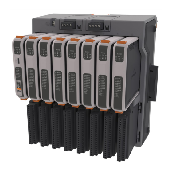
FB3000 RTU Chassis The FB3000 RTU has an eight-slot chassis. The CPU is always in slot one of the base chassis. Figure 1-2: FB3000 RTU – 8-Slot Version (with/without slot covers) Each slot includes an upper section and a lower section. The upper section holds the internal logic for the module and the lower section holds the personality module used for wiring. -
Page 16: Memory
Emerson FB3000 RTU Instruction Manual D301851X012 May 2022 Memory The RTU includes both static and flash memory. Table 1-1: Memory Memory Usage Firmware image and report files; with 104 MB reserved for file system 256 MB Flash and 128 MB available for database and history... -
Page 17: Power
Emerson FB3000 RTU Instruction Manual D301851X012 May 2022 Table 1-2: Maximum I/O Count in Single Chassis # of Slots AI/DI/PI You can purchase one, two, or three extension chassis to connect to the base chassis, to add 8, 16, or 24 additional I/O slots. -
Page 18: Software Tools
Hirschman Eagle One, or the Phoenix mGuard rs4000 (or equivalents). An example of how to install one of these devices to the RTU can be found in the Emerson Remote Automation Solutions MOXA® Industrial Secure Router Installation Guide (part number D301766X012). For further information, contact your Emerson Impact Partner or the individual vendor’s website. -
Page 19: Hazardous Locations
Connecting Communications Ports Hazardous Locations For North America the FB3000 has certifications for Class I Division 2 (Groups A, B, C & D) non- incendive and non-hazardous locations only. For other world areas the FB3000-has ATEX and IEC Ex certifications for Ex ec Zone 2 non-sparking installations and non-hazardous locations only. -
Page 20: Site Considerations
The RTU must reside in an accessible location for configuration and service. Refer to the dimensional drawings for information on the space required. Figure 2-1: FB3000 Dimensions – 8-Slot (with/without DIN Rail mounting plate assembly) No DIN mounting plate in this view. -
Page 21: Connecting Extension Chassis
The FB3000 supports up to 3 additional chassis. When connecting an extension chassis to the “base” chassis (the chassis containing the CPU module), use only the connector on the right hand side of the base chassis. The FB3000 base chassis cannot support an extension chassis using the left-hand connector. -
Page 22: General Wiring Guidelines
Emerson FB3000 RTU Instruction Manual D301851X012 May 2022 Figure 2-2: Removing Chassis Connector Cover 2. Press the two chassis together. If mounting on a DIN rail, slide both chassis onto the DIN rail first to ensure proper alignment and place clamps/brackets at both ends of assembly on DIN rail to ensure side connectors between chassis remain fully engaged. -
Page 23: Grounding
When using shielded cable, ground all shields at a suitable Instrument Earth connection point. This prevents circulating ground current loops that can cause signal errors. See the FB3000 product data sheet for information about applicable standards for EMI and RFI emissions and susceptibility. -
Page 24: Internal System Bus Ground
Emerson FB3000 RTU Instruction Manual D301851X012 May 2022 Figure 2-4: Chassis Ground Lug Location Once you have installed the unit, run a ground wire (14 AWG protective conductor) between the chassis ground lug and a known good earth ground. -
Page 25: Isolated Ground On 3Mix12 Module
Emerson FB3000 RTU Instruction Manual D301851X012 May 2022 Isolated Ground on 3MIX12 Module The 3MIX12 mixed I/O module includes an isolated ground system (ISOGND) on pins 5, 10, 12, and 14 of TB1. ISOGND provides a low noise return (ground) for analog inputs and outputs. It is completely isolated from the other three ground systems. -
Page 26: 24V Loop Ground On 3Mix12 Module
Emerson FB3000 RTU Instruction Manual D301851X012 May 2022 24V Loop Ground on 3MIX12 Module Pin 20 on TB1 of the 3MIX12 mixed I/O module serves as the return side of the +24V loop power supply. It is completely isolated from the other three ground systems. -
Page 27: Mounting The Chassis
Emerson FB3000 RTU Instruction Manual D301851X012 May 2022 Mounting the Chassis The back of the RTU chassis includes a removeable mounting plate with a slot for DIN-rail mounting. The slot accommodates either 7.5 or 15mm DIN rails. Figure 2-7: Chassis Mounting Upper tab;... -
Page 28: Panel Or Wall Mounting The Aluminum Enclosure
Emerson FB3000 RTU Instruction Manual D301851X012 May 2022 Panel or Wall Mounting the Aluminum Enclosure To mount the RTU directly to a wall without using the DIN rail, you must first remove the mounting plate. This exposes four holes into which you can insert screws to mount the RTU to a panel or wall. - Page 29 Emerson FB3000 RTU Instruction Manual D301851X012 May 2022 5. Insert longer screws (screw length depends on the wall/panel)in the holes shown in Figure 2-9 to mount the device to a wall or panel. The shafts of the screws push through the locations...
-
Page 30: Removing Battery Saver Tabs
Emerson FB3000 RTU Instruction Manual D301851X012 May 2022 Removing Battery Saver Tabs When you are ready to install the RTU and place it into operation, you must remove the battery saver tabs for the SRAM coin cell batteries. Each power module, as well as the CPU battery, has a similar tab. -
Page 31: Connecting External Power
Emerson FB3000 RTU Instruction Manual D301851X012 May 2022 Connecting External Power DANGER EXPLOSION HAZARD: Ensure the area in which you perform this operation is non-hazardous. Performing this operation in a hazardous area could result in an explosion. Figure 2-13: External Power Connections The device supports both 12V and 24V power supplies. -
Page 32: Extended Backplane Supported Configurations
If your installation includes multiple chassis, wire power only to the left-most (base) chassis. Note: ‐ If your FB3000 does not power on, check that the polarity of the DC input voltage wiring connections match Figure 2 14. If you accidentally reversed the polarity, it triggers an internal fuse and switch to protect the device from damage. -
Page 33: Removing The I/O Cover
Emerson FB3000 RTU Instruction Manual D301851X012 May 2022 Removing the I/O Cover Apply pressure on both sides of the cover where it meets the chassis and pull the cover off. Figure 2-15: Removing the I/O Cover To replace the cover, line it up with the mating slots on the chassis and press the cover on. -
Page 34: Connecting Communication Ports
Emerson FB3000 RTU Instruction Manual D301851X012 May 2022 2.10 Connecting Communication Ports DANGER EXPLOSION HAZARD: Ensure the area in which you perform this operation is non-hazardous. Performing this operation in a hazardous area could result in an explosion. The communication ports allow you to connect to a PC or laptop running FBxConnect software or to other devices. -
Page 35: Connecting To Com1
Emerson FB3000 RTU Instruction Manual D301851X012 May 2022 Figure 2-16: Configuring a Port in FBxConnect Connecting to COM1 Using the CPU personality module, you can configure the COM1 port as RS-232, RS-485 (4-wire), or RS-485 (2-wire) communications. When connecting COM1 to another device using RS-232, use a cable with configurations as shown... - Page 36 Emerson FB3000 RTU Instruction Manual D301851X012 May 2022 Figure 2-18: COM1 Configured as RS-485 (4-wire) RS-485 (4-wire) port on device Connect cable shields to suitable Instrument Earth connection point Installation...
- Page 37 Emerson FB3000 RTU Instruction Manual D301851X012 May 2022 When connecting COM1 to another device using RS-485 (2-wire), use a cable with configurations as shown in Figure 2-19: Figure 2-19: COM1 Configured as RS-485 (2-wire) RS-485 (2-wire) port on device Connect cable shields to suitable Instrument Earth connection point Regardless of the interface standard –...
-
Page 38: Connecting To Com2
Emerson FB3000 RTU Instruction Manual D301851X012 May 2022 Connecting to COM2 Using the CPU personality module, you can configure the COM2 port as RS-232, RS-485 (4-wire), or RS-485 (2-wire) communications. When connecting COM2 to an RS-232 port on another device (a PC or another controller/RTU) use... - Page 39 Emerson FB3000 RTU Instruction Manual D301851X012 May 2022 When connecting COM2 to an RS-485 (4-wire) port on another device use a cable with configurations as shown in Figure 2-21: Figure 2-21: COM2 Configured as RS-485 (4-wire) RS-485 (4-wire) port on device...
- Page 40 Emerson FB3000 RTU Instruction Manual D301851X012 May 2022 When connecting COM2 to an RS-485 (2-wire) port on another device use a cable with configurations as shown in Figure 2-22: Figure 2-22: COM2 Configured as RS-485 (2-wire) RS-485 (2-wire) port on device Connect cable shields to suitable Instrument Earth connection point Regardless of the interface standard –...
-
Page 41: Connecting To Com3
Emerson FB3000 RTU Instruction Manual D301851X012 May 2022 Connecting to COM3 COM3 can be configured for RS-485 (2-wire) communication. When connecting COM3 to an RS- 485 port on another device (such as a Rosemount 4088B transmitter), use a cable with... - Page 42 Enable AC termination using switches on last multi-dropped 4088B transmitter RS-485 bus; twisted pair required Up to ten 4088B transmitters allowed per port; FB3000 only provides power for a maximum of four transmitters. Any other transmitters require an external power supply.
-
Page 43: Connecting To Com4
Emerson FB3000 RTU Instruction Manual D301851X012 May 2022 Connecting to COM4 You can configure COM4 for RS-485 (2-wire) communication. When connecting COM4 to an RS- 485 port on another device (such as a Rosemount 4088B transmitter), use a cable with configurations as shown below. - Page 44 Enable AC termination using switches on last multi-dropped 4088B transmitter RS-485 bus; twisted pair required Up to ten 4088B transmitters allowed per port; FB3000 only provides power for a maximum of four transmitters. Any other transmitters require an external power supply.
-
Page 45: Ethernet And Micro Usb Ports
Emerson FB3000 RTU Instruction Manual D301851X012 May 2022 Ethernet and Micro USB Ports Located on the top of the CPU module, the two Ethernet ports are standard 8-pin 10/100Base-T RJ - 45 8P8C sockets. Connect to an Ethernet switch using the appropriate Category 5 shielded patch cable. - Page 46 Emerson FB3000 RTU Instruction Manual D301851X012 May 2022 Installation...
-
Page 47: Pulse Inputs
HART ® Input/Output Channels I/O in the FB3000 RTU comes from I/O modules installed in the I/O slots. All wiring is made to the lower bay “personality” modules. WARNING Explosion Hazard: Connect or disconnect only in a non-hazardous area. -
Page 48: Analog Inputs
May 2022 Analog Inputs The FB3000 RTU supports a mixed I/O module which includes eight channels you can individually configure as either analog inputs (AI), digital inputs (DI) or pulse inputs (PI). The number of mixed I/O modules supported depends on the number of I/O slots in the RTU. - Page 49 Emerson FB3000 RTU Instruction Manual D301851X012 May 2022 Figure 3-1: Analog Input (AI) Wiring Using 1-5VDC or 4-20mA External voltage source External current source Power Supply 30VDC Max I/O Configuration and Wiring...
-
Page 50: Analog Outputs
GND (pin 20) externally to ISOGND (in this case pin 10). Figure 3-2: Analog Input (AI) Wiring Using Loop Power External current source Analog Outputs The FB3000’s mixed I/O modules includes two dedicated analog output channels, with the following characteristics: Table 3-3: Analog Output Characteristics Type... -
Page 51: Ao Wiring
Emerson FB3000 RTU Instruction Manual D301851X012 May 2022 Type Number Supported Characteristics Can be configured to fail either at last good output value or as a preset value. 3.2.1 AO Wiring Figure 3-3 shows how to wire the analog output. -
Page 52: Digital Inputs
Digital Inputs The FB3000 RTU supports a mixed I/O module which includes eight channels you can individually configure as either analog inputs (AI), digital inputs (DI) or pulse inputs (PI). The number of mixed I/O modules supported depends on the number of I/O slots in the RTU. -
Page 53: Di Wiring
AIDIPI_6. Figure 3-4: Digital Input (DI) Wiring (internal pull-up enabled) Digital Outputs The mixed I/O modules of the FB3000 RTU include two dedicated digital output channels. Notes When using a digital output to drive an inductive load (such as a relay coil), place a ... - Page 54 Emerson FB3000 RTU Instruction Manual D301851X012 May 2022 When configured as digital outputs, the channels have the following characteristics: Table 3-5: Digital Output Characteristics Type Number Supported Characteristics Digital Output (DO) 2 dedicated channels Contact closure by solid state relay ...
-
Page 55: Do Wiring
Emerson FB3000 RTU Instruction Manual D301851X012 May 2022 3.4.1 DO Wiring Figure 3-5 shows how to wire the digital output using the low side internal switch. In the figure, DOHI_1/DOLO_1 are configured to use the internal ground switch that you enable within FBxConnect. - Page 56 Emerson FB3000 RTU Instruction Manual D301851X012 May 2022 Figure 3-6 shows how to wire a digital output using the 24V internal loop power supply. as a high side external switch. This configuration uses the internal ground switch to connect the DOLO_1 side to ground.
- Page 57 Emerson FB3000 RTU Instruction Manual D301851X012 May 2022 Figure 3-7 shows how to wire a digital output as a dry contact closure. Figure 3-7: Digital Output (DO) Wiring – Dry Contact Closure 500 mA load max field device 30VDC Max Power Supply...
- Page 58 Emerson FB3000 RTU Instruction Manual D301851X012 May 2022 Figure 3-8 shows how to wire a digital output as a contact closure using the internal 24V loop supply. The total current for all devices connected to a DO channel must not exceed 500 mA.
-
Page 59: Pulse Inputs
May 2022 Pulse Inputs The FB3000 RTU supports a mixed I/O module which includes eight channels you can individually configure as either analog inputs (AI), digital inputs (DI) or pulse inputs (PI). The number of mixed I/O modules supported depends on the number of I/O slots in the RTU. -
Page 60: Pi Wiring
The FB3000 RTU supports a HART ® (Highway Addressable Remote Transducer) module with four (4) channels. This allows the FB3000 to communicate with external HART devices such as transmitters. Insert the 3HRT04 module in any base chassis slot except slot 1 and insert its corresponding 3HTSG4 module below it. -
Page 61: Wiring The 3Hrt04 Module
Emerson FB3000 RTU Instruction Manual D301851X012 May 2022 Table 3-7: HART Characteristics Number Type Characteristics Supported HART channel 1 to 4 An individual HART channel can be configured in FBxConnect as either an input or an output, but not both. -
Page 62: Multi-Drop Mode
Emerson FB3000 RTU Instruction Manual D301851X012 May 2022 3.6.1.2 Multi-Drop Mode In Multi-Drop Mode, only the HART digital signaling (FSK – Frequency Shift Keying) is present and 4-20mA analog current signal is permitted (no AO allowed). Each device can support a maximum 4mA bias current. Because the maximum rated output (sink) current of any 3HRT04 Module channel is 20mA, and each device can draw 4mA, a HART channel in multidrop mode supports a total of 5 HART devices. - Page 63 Emerson FB3000 RTU Instruction Manual D301851X012 May 2022 Figure 3-12 shows how to wire a HART channel for devices which do not use loop power but get power from an external power supply. Figure 3-12: HART Wiring – External Power Supply...
-
Page 64: Analog Input Mode (Hart Communication Disabled)
Emerson FB3000 RTU Instruction Manual D301851X012 May 2022 3.6.1.3 Analog Input Mode (HART Communication Disabled) If you have an unused HART channel, you can use it as a 4-20mA analog input (AI current mode). In FBxConnect, you must Enable the 250-Ohm Termination Resistor and set the HART Comm Mode to Disabled. -
Page 65: Analog Output Mode (Hart Communication Disabled)
Emerson FB3000 RTU Instruction Manual D301851X012 May 2022 3.6.1.4 Analog Output Mode (HART Communication Disabled) If you have an unused HART channel, you can use it as a 4-20mA current sinking analog output. In FBxConnect, you must Disable the 250 Ohm Termination Resistor and set the HART Comm Mode to Disabled. -
Page 66: Software Configuration
Emerson FB3000 RTU Instruction Manual D301851X012 May 2022 3.6.2 Software Configuration Consult the FBxConnect online help for full details. What follows is an overview of the steps: 1. From the Configure tab in FBxConnect, click I/O Setup > HART. 2. Select the HART channel you want to configure; there are four HART channels per module. - Page 67 Emerson FB3000 RTU Instruction Manual D301851X012 May 2022 9. Select the variables you want to poll from the device, then click Save and Close the screen. 10. If this channel uses multi-drop, repeat steps 8 and 9 for any unconfigured devices.
- Page 68 Emerson FB3000 RTU Instruction Manual D301851X012 May 2022 I/O Configuration and Wiring...
-
Page 69: Powering Up/Powering Down The Device
Ethernet switch with an appropriate Category 5 shielded patch cable. Decide which communication protocol you will use. This could be DNP3 or Modbus. See these documents for more information: DNP3 Protocol Specifications Manual (for Emerson FB3000 RTUs) (D301858X012) Operation... -
Page 70: Communicating With A Laptop Using A Serial Port
Emerson FB3000 RTU Instruction Manual D301851X012 May 2022 FBxConnect Configuration Software User Manual (for the FB3000 RTU) (D301882X012) Provide the SCADA host with information about the various parameters it needs to extract from the application running in the RTU. Typically, the SCADA host software includes a utility that allows you to identify this information so it can be incorporated into the database at the SCADA host. -
Page 71: Communicating With A Laptop Using Ethernet
Emerson FB3000 RTU Instruction Manual D301851X012 May 2022 4.2.3 Communicating with a Laptop Using Ethernet Your laptop must have Field Tools software with FBxConnect software installed. You must know a valid username/password combination for the RTU. WARNING Explosion Hazard – Connect or disconnect only in a non-hazardous area. - Page 72 Emerson FB3000 RTU Instruction Manual D301851X012 May 2022 Operation...
- Page 73 Emerson-authorized repair facility. Important Only use batteries supplied with the RTU or sold by Emerson Remote Automation Solutions as spare parts for this RTU. If you substitute a battery you obtain elsewhere you will void your hazardous location certification unless it is the identical part from the same manufacturer as that supplied with the RTU from Emerson.
-
Page 74: Returning The Unit For Repairs
Only certain field replacement procedures are allowed under warranty and hazardous location certification. Other types of repairs cannot be performed in the field. In those cases, you must ship the unit to an Emerson-authorized repair facility. Contact Emerson Remote Automation Solutions for a return authorization number and instructions for where to ship the unit. -
Page 75: Interpreting The Status Leds
Emerson FB3000 RTU Instruction Manual D301851X012 May 2022 Interpreting the Status LEDs Each of the modules in the RTU includes status light-emitting diodes (LEDs.) The meaning of each LED varies depending upon the color displayed or whether the LED flashes. - Page 76 Emerson FB3000 RTU Instruction Manual D301851X012 May 2022 Table 5-1: LED Descriptions: CPU Module Color/State Meaning Module Status Flashing GREEN rapidly Boot memory update in progress Flashing GREEN once per second Normal operations RED for approximately 5 seconds Boot in progress...
- Page 77 Emerson FB3000 RTU Instruction Manual D301851X012 May 2022 Color/State Meaning Flashing GREEN USB receive or transmit in progress. Flashing GREEN with Module CPU module is in wrong slot Status LED alternating RED and (must be in slot 1). If this...
- Page 78 Emerson FB3000 RTU Instruction Manual D301851X012 May 2022 Table 5-2: LED Descriptions: Mixed I/O Module Color/State Meaning Module Status GREEN Power good Failure No power Communication Flashing GREEN Message send to CPU in Status progress No communication with CPU Flashing RED every 4 seconds...
- Page 79 Emerson FB3000 RTU Instruction Manual D301851X012 May 2022 Color/State Meaning AO1 and AO2 GREEN Normal Flashing RED In alarm Failure Flashing ORANGE Override and failure ORANGE Override Disabled DO1 and DO2 GREEN DO is on Flashing RED (Reserved) Failure Flashing ORANGE...
-
Page 80: Removing/Replacing The Power Module
Emerson FB3000 RTU Instruction Manual D301851X012 May 2022 Table 5-3: LED Descriptions: HART ® I/O Module Color/State Meaning Module Status GREEN Power good Failure No power Communication Flashing GREEN Message send to CPU in Status progress No communication with CPU... - Page 81 Emerson FB3000 RTU Instruction Manual D301851X012 May 2022 If you have two power modules installed, you can remove either one of them (but not both) while the RTU is operating: Removing a Power Module Disconnect the terminal block from the power module you want to remove.
-
Page 82: Removing/Replacing The Sram Batteries
Emerson FB3000 RTU Instruction Manual D301851X012 May 2022 Removing/Replacing the SRAM Batteries A 3V lithium coin cell battery in each of the two power supply modules provides backup power for the SRAM and the real time clock. These batteries operate continuously with a typical expected cumulative operation of 4900 hours if only one power module is installed, or 9800 hours if both power modules are installed. - Page 83 Emerson FB3000 RTU Instruction Manual D301851X012 May 2022 DANGER EXPLOSION HAZARD: BATTERIES MUST ONLY BE CHANGED IN AN AREA FREE OF IGNITABLE CONCENTRATIONS. Battery in Power Module: Remove the power module. Grasp the battery and pull it out of the power module.
-
Page 84: Removing/Replacing The Cpu Module (3Cpu16)
Emerson FB3000 RTU Instruction Manual D301851X012 May 2022 Removing/Replacing the CPU Module (3CPU16) DANGER Ensure the RTU is in a non-hazardous area. Never open the enclosure in a hazardous area. DANGER EXPLOSION HAZARD: Ensure the area in which you perform this operation is non- hazardous. -
Page 85: Removing/Replacing An I/O Module (3Mix12)
Emerson FB3000 RTU Instruction Manual D301851X012 May 2022 Press the new replacement module into slot 1 until it is properly seated. Figure 5-8: Replacing the CPU Module Restore power. Restore the configuration backed up from step 1. Removing/Replacing an I/O Module (3MIX12) DANGER Ensure the RTU is in a non-hazardous area. - Page 86 Emerson FB3000 RTU Instruction Manual D301851X012 May 2022 Figure 5-9: Removing an I/O Module Press the new replacement module into the slot until it is properly seated. Figure 5-10: Replacing an I/O Module Service and Troubleshooting...
-
Page 87: Removing/Replacing A Personality Module
Emerson FB3000 RTU Instruction Manual D301851X012 May 2022 Removing/Replacing a Personality Module DANGER Ensure the RTU is in a non-hazardous area. Never open the enclosure in a hazardous area. DANGER EXPLOSION HAZARD: Ensure the area in which you perform this operation is non- hazardous. -
Page 88: Upgrading System Firmware
Emerson FB3000 RTU Instruction Manual D301851X012 May 2022 Upgrading System Firmware Periodically Emerson releases new system firmware for the RTU to introduce new features or update system functions. You must know a valid username/password combination for the RTU to complete this process. DANGER Switch the process this RTU controls over to whatever manual/backup system you have. -
Page 89: Backing Up Historical Data And Your Configuration
Emerson FB3000 RTU Instruction Manual D301851X012 May 2022 Figure 5-13: Firmware Update Dialog Box Select the checkbox in the Selected column to choose the firmware. If you are downloading the same version that is already installed on the device, select Download selected packages even if they are unchanged. -
Page 90: Backing Up Your Solution
Emerson FB3000 RTU Instruction Manual D301851X012 May 2022 Connect your laptop to one of the available ports on the RTU. Launch Field Tools and use FBxConnect to connect to the RTU. Click Services > Firmware Update. Click Configuration Save to save the RTU’s configuration in a file on your laptop. - Page 91 COM4 Figures wiring ..............31 1-1. FB3000 RTU .............1 Communicating via a serial port ....... 59 1-2. FB3000 RTU - 8-Slot Version ......3 Communication 2-1. FB3000 Dimensions .........8 establishing ............57 2-2. Removing Chassis Connector Cover ....10 to a laptop through an Ethernet port ....59 2-3.
- Page 92 Emerson FB3000 RTU Instruction Manual D301851X012 May 2022 2-8. DIN rail clamps installation location for 5-10. Replacing I/O Module ......... 74 extension chassis assembly ....... 15 5-11. Removing Personality Module ....75 2-9. Panel or Wall Mounting ......... 16 5-12. Replacing Personality Module ..... 75 2-10.
- Page 93 Emerson FB3000 RTU Instruction Manual D301851X012 May 2022 turning ON or OFF ..........57 2-3. Extended Backplane Supported Configurations Power Module ................ 20 replacing .............. 69 2-4. COM Terminal Block ........22 Pulse Inputs ............. 47 3-1. Supported I/O Modules ........ 35 3-2.
- Page 96 1 Pandan Crescent end-user. Emerson Automation Solutions, Emerson, and the Emerson logo are trademarks and Singapore 128461 service marks of Emerson Electric Co. All other marks are the property of their respective T +65 6777 8211| F +65 6777 0947 owners.
Need help?
Do you have a question about the FB3000 and is the answer not in the manual?
Questions and answers
what is the part # for this comm card
The context does not provide a specific part number labeled as the communication card for the Emerson FB3000. However, communication ports such as COM1, COM2, COM3, and COM4 are mentioned, and the CPU Module Assembly, which likely handles communication functions, has part numbers 400224-01-0 and 510009-01-0 with ordering code 3CPU16.
Therefore, the part number for the FB3000 CPU Module Assembly, which includes communication capabilities, is 400224-01-0 or 510009-01-0.
This answer is automatically generated