
Related Manuals for Endress+Hauser HART iTEMP TMT182B


Summary of Contents for Endress+Hauser HART iTEMP TMT182B
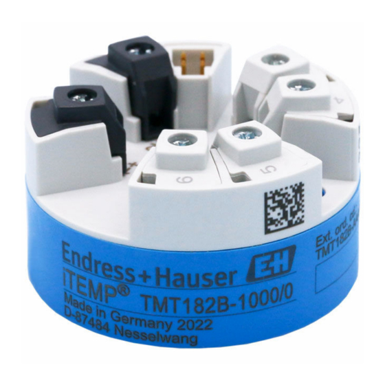
- Page 1 Products Solutions Services BA02260T/09/EN/01.22-00 71590122 2022-08-30 Operating Instructions iTEMP TMT182B Temperature transmitter...
- Page 2 This symbol alerts you to a dangerous situation. Failure to avoid this situation can result in minor or medium injury. NOTICE This symbol contains information on procedures and other facts which do not result in personal injury. 1.3.2 Electrical symbols Symbol Meaning Direct current Alternating current Direct current and alternating current Endress+Hauser...
- Page 3 Symbols in graphics Symbol Meaning Symbol Meaning 1, 2, 3,... Item numbers … Series of steps A, B, C, ... Views A-A, B-B, C-C, ... Sections Hazardous area Safe area (non-hazardous area) Tool symbols Symbol Meaning Phillips head screwdriver A0011219 Endress+Hauser...
- Page 4 The document serves as a reference for parameters: it provides a detailed GP01197T explanation for each individual parameter in the operating menu. The document types listed are available: In the Download Area of the Endress+Hauser Internet site: www.endress.com→ Download Registered trademarks HART®...
- Page 5 EMC requirements as per the IEC/EN 61326 series and the NAMUR recommendations NE 21. NOTICE ‣ The device must only be powered by a power unit that operates using an energy-limited electric circuit according to UL/EN/IEC 61010-1, Section 9.4 and the requirements in Table 18. Endress+Hauser...
- Page 6 • During commissioning, any passwords that were used at delivery should be changed. • Follow the general rules for generating a secure password when defining and managing the password. • The user is responsible for the management and careful handling of passwords. Endress+Hauser...
- Page 7 (www.endress.com/deviceviewer): All data relating to the device and an overview of the Technical Documentation supplied with the device are displayed. • Enter the serial number on the nameplate into the Endress+Hauser Operations App or scan the 2-D matrix code (QR code) on the nameplate with the Endress+Hauser Operations App: all the information about the device and the technical documentation pertaining to the device is displayed.
- Page 8 Pack the device for storage and transportation in such a way that it is reliably protected against impact and external influences. The original packaging offers the best protection. Avoid the following environmental influences during storage: • Direct sunlight • Vibration • Aggressive media Endress+Hauser...
- Page 9 • Maximum torque for securing screws = 1 Nm (¾ foot-pound), screwdriver: Pozidriv Z2 • Maximum torque for screw terminals = 0.35 Nm (¼ foot-pound), screwdriver: Pozidriv A0046845 1 Head transmitter mounting Mounting in a terminal head (terminal head flat face as per DIN 43729) Terminal head Snap rings Insert Endress+Hauser...
- Page 10 (2). Then fix both mounting screws with the snap rings (3). 3. Screw the head transmitter (2) onto the DIN rail clip (4). 4.2.1 Mounting typical of North America A0008520 2 Head transmitter mounting Thermowell Insert Adapter, coupling Terminal head Head transmitter Mounting screws Endress+Hauser...
- Page 11 Are the device, the connections and connecting cables free of damage (visual inspection)? Do the ambient conditions match the device specification (e.g. ambient temperature, See the ' T echnical measuring range, etc.)? data' section Have connections been established correctly and with the specified torque? Endress+Hauser...
- Page 12 ® transmitter via the HART ® protocol (terminals 1 and 2). NOTICE ‣ ESD – Electrostatic discharge. Protect the terminals from electrostatic discharge. Failure to observe this may result in the destruction or malfunction of parts of the electronics. Endress+Hauser...
- Page 13 Shielding and grounding the signal cable at one end with HART communication Optional grounding of the field device, isolated from cable shielding Grounding of the cable shield at one end Supply unit Grounding point for HART ® communication cable shield Endress+Hauser...
- Page 14 Are the mounted cables relieved of tension? Are the power supply and signal cables connected → 12 correctly? Are all of the screw terminals well-tightened? Are all the cable entries mounted, tightened and leak- tight? Are all housing covers installed and firmly tightened? Endress+Hauser...
- Page 15 Operation options Operation options Overview of operation options A0050743 7 Operation options for the transmitter via HART® communication Temperature transmitter Transmitter active barrier with bidirectional HART® signal transmission HART® modem PC, laptop or tablet with FieldCare/DeviceCare operating tools Endress+Hauser...
- Page 16 Information Serial number Device HART-Info Device type A0051066 User roles Endress+Hauser' s role-based access concept consists of two hierarchical levels for the user and presents the various user roles with defined read/write authorizations derived from the NAMUR shell model. Endress+Hauser...
- Page 17 Maintenance user role. A password can be defined at different points in the operation of the device: In the menu: Guidance → Commissioning wizard: as part of guided device operation In the menu: System → User management Endress+Hauser...
- Page 18 DeviceCare Function scope DeviceCare is a free configuration tool for Endress+Hauser devices. It supports devices with the following protocols, provided a suitable device driver (DTM) is installed: HART, PROFIBUS, FOUNDATION Fieldbus, Ethernet/IP, Modbus, CDI, ISS, IPC and PCP. The target group comprises customers without a digital network in plants and service centers as well as Endress+Hauser service technicians.
- Page 19 FieldCare Function scope FDT/DTM-based plant asset management tool from Endress+Hauser. It can configure all smart field units in a system and helps you manage them. By using the status information, it is also a simple but effective way of checking their status and condition. Access is via the HART ®...
- Page 20 Displays device name, current status, current measured values Menu navigation, device parameterization, help section 6.3.3 AMS Device Manager Function scope Program from Emerson Process Management for operating and configuring measuring devices via the HART ® protocol. Source for device description files See information → 22. Endress+Hauser...
- Page 21 SIMATIC PDM Function scope SIMATIC PDM is a standardized, vendor-independent program from Siemens for the operation, configuration, maintenance and diagnosis of intelligent field devices via the HART ® protocol. Source for device description files See information → 22. Endress+Hauser...
- Page 22 Endress+Hauser' s FieldCare and DeviceCare operating tools are also available for download (www. endress.com --> Downloads --> Search field: Software --> Application software) or on the data storage medium which you can obtain from your local Endress+Hauser sales organization. Measured variables via HART protocol...
- Page 23 Write primary variable damping value 35, Cmd035 Write primary variable range values 40, Cmd040 Enter/Exit fixed current mode 42, Cmd042 Perform device reset 44, Cmd044 Write primary variable units 45, Cmd045 Trim loop current zero 46, Cmd046 Trim loop current gain Endress+Hauser...
- Page 24 Read Process Unit Tag 521, Cmd521 Write Process Unit Tag 523, Cmd523 Read Condensed Status Mapping Array 524, Cmd524 Write Condensed Status Mapping Array 525, Cmd525 Reset Condensed Status Mapping Array 526, Cmd526 Write Simulation Mode 527, Cmd527 Simulate Status Bit Endress+Hauser...
- Page 25 "Device management" is the first section that appears when the user runs the wizard, and contains the following parameters. Its main purpose is to provide information about the device: Navigation Guidance → Commissioning → Start Endress+Hauser...
- Page 26 "Maintenance" role for the first time. Navigation Guidance → Commissioning → User management A0037391-EN Access status New password Confirm new password 1. The Maintenance role appears in the "Access status" picklist. Afterwards, the New password and Confirm new password input boxes appear. Endress+Hauser...
- Page 27 The parameters are also protected against modification by logging out of the Maintenance user role and switching to the Operator role. To disable the write protection, the user must log on with the Maintenance user role via the relevant operating tool. User role concept → 16 Endress+Hauser...
- Page 28 Check that the sensor is connected correctly. The cable resistance of the sensor (2- Compensate the cable resistance. wire) was not compensated. Offset incorrectly set. Check offset. Failure current (≤ 3.6 mA or Faulty sensor. Check the sensor. ≥ 21 mA) Endress+Hauser...
- Page 29 The device is in the service mode (e.g. during a simulation). Out of The device is being operated outside its technical specifications (e.g. during specification startup or cleaning processes). Maintenance Maintenance is required. required categorized As per NAMUR NE107 Endress+Hauser...
- Page 30 Replace device Alarm defective Diagnostic of configuration Factory reset active Factory reset in progress, please Warning wait Initialization active Initialization in progress, please Warning wait Initialization active Warning Data transfer failed 1. Check connection Alarm 2. Repeat data transfer Endress+Hauser...
- Page 31 Change to functions and operation. Compatible. The Operating Instructions change. Fixes and internal changes. No changes to the Operating Instructions. Date Firmware version Changes Documentation 12/2022 01.01.zz Original firmware BA02260T, Version 01.22 Maintenance No special maintenance work is required for the device. Endress+Hauser...
- Page 32 Various accessories, which can be ordered with the device or subsequently from Endress +Hauser, are available for the device. Detailed information on the order code in question is available from your local Endress+Hauser sales center or on the product page of the Endress+Hauser website: www.endress.com.
- Page 33 HART For details, see Technical Information TI404F/00 Commubox FXA291 Connects Endress+Hauser field devices with a CDI interface (= Endress+Hauser Common Data Interface) and the USB port of a computer or laptop. For details, see Technical Information TI405C/07 WirelessHART adapter Is used for the wireless connection of field devices.
- Page 34 DeviceCare is the tool developed by Endress+Hauser for the configuration of Endress+Hauser devices. All smart devices in a plant can be configured via a point- to-point or point-to-bus connection. The user-friendly menus enable transparent and intuitive access to the field devices.
- Page 35 For details, see Technical Information TI01043K RNB22 System power supply unit with wide-range input 100 to 240 V / 110 to 250 V Primary switch mode power supply unit, single-phase, output 24 V / 2.5 A For details, see Technical Information TI01585K Endress+Hauser...
- Page 36 –200 to +600 °C (–328 to +1 112 °F) –150 to +600 °C (–238 to +1 112 °F) GOST R8.585-2001 Type L (NiCr-CuNi) (43) –200 to +800 °C (–328 to +1 472 °F) –200 to +800 °C (+328 to +1 472 °F) 50 K (90 °F) Endress+Hauser...
- Page 37 Manufacturer ID 17 (0x11) Device type ID 0x11D2 HART ® specification Device address in multi-drop mode Software setting addresses 0 to 63 Device description files (DTM, DD) Information and files available at: www.endress.com www.fieldcommgroup.org HART load Min. 250 Ω Endress+Hauser...
- Page 38 Thermocouples (TC) and voltage transmitters (mV) ≤ 1 s Reference temperature ≤ 1 s When recording step responses, it must be taken into account that the times of the internal reference measuring point are added to the specified times where applicable. Endress+Hauser...
- Page 39 –180 to +200 °C (–292 to +392 °F) ME = ± (0.08 °C (0.14 °F) + 0.003% * (MV - LRV)) OIML R84: 2003 / GOST 6651-2009 Ni100 (12) –60 to +180 °C (–76 to +356 °F) ME = ± (0.08 °C (0.14 °F) - 0.004% * (MV - LRV)) Ni120 (13) Endress+Hauser...
- Page 40 Measured value transmitted via HART Percentages based on the configured span of the analog output signal. Deviations from maximum measured error possible due to rounding. Total measured error of transmitter at current output = √(Measured error digital² + Measured error D/A²) Endress+Hauser...
- Page 41 The sensor-specific coefficients are then sent to the transmitter. Sensor-transmitter matching using one of the methods mentioned above significantly improves the temperature measurement accuracy of the entire system. This is because the Endress+Hauser...
- Page 42 0.003 % 0.003 % 10 to 2 000 Ω 0.0013% * MV, at least 12 mΩ 0.0008% * MV, at least 7 mΩ Measured value transmitted via HART ® Percentages based on the configured span of the analog output signal Endress+Hauser...
- Page 43 0.03 °C (0.05 °F) ≤ 0.0077% * (MV - LRV) or ≤ 0.0102% * (MV - LRV) or ≤ 0.0112% * (MV - LRV) or Pt100 (5) JIS C1604:1984 0.02 °C (0.04 °F) 0.03 °C (0.05 °F) 0.03 °C (0.05 °F) Endress+Hauser...
- Page 44 0.45 °C (0.81 °F) 0.48 °C (0.86 °F) R8.585-2001 Voltage transmitter (mV) –20 to 100 mV ≤ 0.027% * MV or 9 µV ≤ 0.035% * MV or 12 µV ≤ 0.038% * MV or 13 µV Whichever is greater Endress+Hauser...
- Page 45 Maximum measured error <1% of measuring range. Interference immunity as per IEC/EN 61326 series, industrial requirements Interference emission as per IEC/EN 61326 series, Class B equipment Insulation class Class III Overvoltage category Overvoltage category II Endress+Hauser...
- Page 46 HART® Communication Protocol Specifications, Revision 7. MTTF 168 years The mean time to failure (MTTF) denotes the theoretically expected time until the device fails during normal operation. The term MTTF is used for systems that cannot be repaired, e.g. temperature transmitters. Endress+Hauser...
- Page 48 *71590122* 71590122 www.addresses.endress.com...