
Subscribe to Our Youtube Channel
Related Manuals for Endress+Hauser iTEMP PCP TMT 121


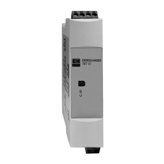
Summary of Contents for Endress+Hauser iTEMP PCP TMT 121
- Page 1 ® iTEMP PCP TMT 121 BA 156R/24/ae/08.03 51006707 Temperature DIN rail transmitter Operating instructions...
- Page 2 Preparing the communication with PC configuration software ➪ Page 13 Instrument configuration (including a description of the unit functions) A complete description of all the functions as well as a detailed overview of the functionality can be found in this chapter. Endress+Hauser...
-
Page 3: Table Of Contents
Temperature DIN rail transmitter Endress+Hauser Table of contents Safety notes..... 4 Technical Data ....20 Designated use . -
Page 4: Safety Notes
Warning! Electrical shock could cause death or serious injury. If the sensor is installed in a high voltage environment and a fault or installation error occurs, high voltage may be present on the transmitter leads and terminals. Endress+Hauser... -
Page 5: Operational Safety
– Devices that are used in hazardous areas or cables for such devices must have the corresponding type of protection. Safe area (non-hazardous areas)! This symbol identifies the non-hazardous area in the diagrams in these Operating Instructions. – Devices in non-hazardous areas must also be certified if connection cables run through a hazardous area. Endress+Hauser... -
Page 6: Identification
CE mark. UL recognized component to UL 3111-1 GL German Lloyd marine approval GL Type Approval for temperature measurements in hazardous locations on GL Classed Vessels, Marine and Offshore Installations. Endress+Hauser... -
Page 7: Delivery Contents
® ® • iTEMP and ReadWin 2000 are registered trademarks of Endress+Hauser Wetzer GmbH + Co. KG, Nesselwang, Germany Installation Installation conditions • When installing and operating the unit, please take note of the allowable ambient temperature (see chapter 10 "Technical Data"). -
Page 8: Installation
• Install and tighten the connection head cover. Enclosure covers must be completely engaged to meet explosion-proof area requirements. Fig. 3: Installation of DIN rail TMT 121 transmitter. 1 thermowell 2 sensor 3 extension nipples and adapters 4 connection head 5 TMT 121 transmitter Endress+Hauser... - Page 9 • Run the sensor lead wires from the sensor assembly to the TMT 121 transmitter. • Attach the sensor wires to the TMT 121 transmitter. Fig. 4: Installing the TMT 121 DIN rail transmitter Endress+Hauser...
-
Page 10: Wiring
Note! The screws on the terminals must be screwed in tightly. • PC configuration (SETUP socket): Connect the SETUP connection cable (see Fig. 5). Endress+Hauser... -
Page 11: Ground The Transmitter
3.75 kV AC (from the sensor input to the output), so the input circuit may also be grounded at any single point. When using a grounded thermocouple, the grounded junction serves as this point. Endress+Hauser... -
Page 12: Operation
RS232C connector screws to the PC. If the PC does not have a RS232 serial interface, use a USB (UNIVERSAL SERIAL BUS) converter. Full compliance with the USB specifications Version 1.0.11.1 and USB CDC Version 1.1 are required to support the RS232 serial interface. Endress+Hauser... -
Page 13: Commissioning
• For detailed operating instructions for the PC configuration software please read the online documentation (BA137R/09/ae) contained in the PC operation and readout software (see folder ’Doc’). This software can be downloaded free of charge from the Internet at the following address: www.readwin2000.com Endress+Hauser... - Page 14 Input: Limitation values see ’Sensor type’ range start value 0 °C Input of 20 mA value. Measurement Input: Limitation values see ’Sensor type’ range end value 100 °C On sensor type polynom RTD, see description ’Customer specific linearization’ Coefficient X0 to Endress+Hauser...
- Page 15 Input of the simulation value (current). Input: 3.8 to 20.5 mA Customer-specific linearization Customer-specific linearization and sensor matching are activated after the POLYNOM RTD sensor type is selected. Please find detailed information about linearization in the PC configuration software. Endress+Hauser...
-
Page 16: Maintenance
Configuration set for PC SETUP (SETUP program and PC serial interface cable (TTL/RS 232C): → Order No.: TMT121A-VM. ® ReadWin 2000 PC SETUP program can be downloaded free of charge from the internet from the following address: www.readwin2000.com Please contact your supplier when ordering! Endress+Hauser... -
Page 17: Trouble-Shooting
No power supply on the 2-wire Check the current loop connection No communication Power supply too low (< 8 V) Check power supply Defective interface cable Check interface cable Defective interface Check PC interface Defective device Replace device Endress+Hauser... - Page 18 (≤ 3.6 mA or ≥ 21 mA) Incorrect 2-wire connection (current Connect the cables correctly (see loop) connection diagram) No power supply on the 2-wire Check current loop; the supply connection should be > 12 V Defective device Replace device Endress+Hauser...
-
Page 19: Returns
DIN rail transmitter please take note of the local disposal regulations. Software history 1.00.00 / 10.2001 Original software Compatible with: • Readwin® 2000 1.2.2 and higher 1.01.00 / 04.2003 Original software Compatible with: • Readwin® 2000 1.12.0 and higher New: By measuring °F, values are stored with higher precision. Endress+Hauser... -
Page 20: Technical Data
(0 to 20 Ω) • Sensor cable resistance max. 11 Ω per cable in the 3- and 4-wire system • Sensor current: ≤ 0.6 mA Resistance Ω 10 to 400 Ω 10 Ω Resistance transmitter 10 to 2000 Ω 100 Ω Endress+Hauser... -
Page 21: Output
Sensor break; sensor short circuit To NAMUR NE 43 ≥ 21.0 high Source impedance max. (V - 12V) / 0.022 A (current Power supply output) e.g. (24 V - 12V)/0.022 A = 545.5Ω Transmission behavior Temperature linear, resistance linear, voltage linear Endress+Hauser... -
Page 22: Power Supply
-10 to 100 mV Voltage transmitters (mV) % is related to the adjusted measurement range. The value to be applied is the greater. Influence of supply voltage • ≤ ±0.01%/V deviation from 24 V Values refer to the full scale value. Endress+Hauser... -
Page 23: Installation Conditions
-40 to 212 °F (-40 to +100 °C) Climate class as per IEC 60654-1, class C Condensation allowed Degree of protection NEMA 1 (IP 20) Shock and vibration 4g / 2 to 150 Hz as per IEC 60 068-2-6 resistance Endress+Hauser... -
Page 24: Mechanical Construction
Mechanical construction Design, dimensions Fig. 7: Dimensions of the DIN rail transmitter in inches (mm) Weight approx. 3.2 oz (90 g) • Housing: Material Plastic PC / ABS, UL 94V0 Terminals Cable up to max. 16 AWG (secure screws) Endress+Hauser... -
Page 25: Human Interface
The measurement system fulfils the requirements demanded by the EU regulations. Endress+Hauser acknowledges successful unit testing by adding the CE mark. • FM IS, Class I, Div. 1+2, Group A, B, C, D / FM NI, Class I, Div. 2, Group A, B, C, D Hazardous area approvals •... - Page 26 Class I / Zone 0 IIC Nonhazardous Locations NI / Class I / Division 2 / Groups ABCD 3 4 5 6 TMT 121 TMT 121 ENDRESS+HAUSER Associated Intrinsically Apparatus e.g. RN 221N Intrinsically safe loop power supply supply with suitable...
- Page 27 Class I / Zone 1 / Ex ia IIC Nonhazardous Locations NI / Class I / Division 2 / Groups ABCD 3 4 5 6 TMT 121 ENDRESS+HAUSER TMT 121 Associated Intrinsically Apparatus e.g. RN 221N Intrinsically safe loop power supply...
-
Page 28: Index
Temperature DIN rail transmitter Endress+Hauser Index Online documentation ..... 13 Returns ....... . . 19 Safety message . - Page 29 Please note that the issuance of a Return Authorization number does not automatically mean that credit will be issued, or that the return is covered by our warranty. An Endress+Hauser associate will contact you regarding the disposition of your returned equipment.
- Page 30 BA 156R/24/ae/08.03 51006707 FM+SGML6.0 ProMoDo...
Need help?
Do you have a question about the iTEMP PCP TMT 121 and is the answer not in the manual?
Questions and answers