Table of Contents
Advertisement
Advertisement
Table of Contents

Related Manuals for Carbide 3D Shapeoko 5 Pro


Summary of Contents for Carbide 3D Shapeoko 5 Pro
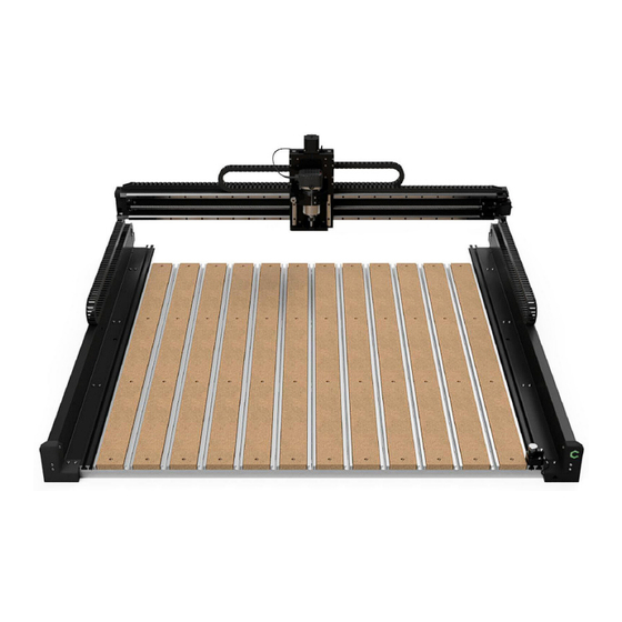
- Page 1 Shapeoko 5 Pro CNC Router Assembly Guide...
-
Page 2: Table Of Contents
Table of Contents WELCOME AND CONGRATULATIONS . . . . . . . . . . . . . . . . . . . . . . . . . . . . . . . . . . . . . . . . . . . . . . . . . . . . . . . . . . . . . . 2 INVENTORY . -
Page 3: Welcome And Congratulations
30 days that you own your Shapeoko, we’ll replace any Shipping Box 2 Contains Carbide 3D-branded item that’s damaged, even if it’s your fault . Details about what’s covered can be found at X-Axis Gantry Assembly Hybrid Table Extrusions and MDF Strips (Nested Together) shop.carbide3d.com/pages/mistakes-are-on-us. -
Page 4: Unpack Box 1
Items Needed in Step 1 1.1 Unpack Box 1 1.2 Position Baseframe Description In Box 1, locate the box labeled Open Me First, Position the four baseframe members Baseframe Members remove the tool bag, and set the box aside. horizontally across your table about 15.7 inches apart, center to center. -
Page 5: Install Y-Right Assembly
At location 1, the BHCS insert through the b. At location 1, the BHCS insert through the holes in the end cap. a. Y-Right has a Carbide 3D logo on the front a. Y-Left has a blank front plate. holes in the end cap. -
Page 6: Install The Cable Track
The X-Axis gantry assembly is heavy and can easily 2. Install the cable track to the last baseframe a. Shapeoko 5 Pro gantry (note that the X-Axis Pull the Y-Right carriage all the way to the front tip over. If the gantry tips over, the mating faces on member at the back of the machine. -
Page 7: Square The Machine
1.9 Square the Machine Check that the Y-Right and Y-Left carriages 3. From the right side of the machine, push the NOTE: The Y-Left extrusion is slotted. When 5. Push the gantry back to the third baseframe are still pushed all the way to the front of the gantry toward the front of the machine until it attaching the left side of the gantry, you can slide the member and tighten the screws on the right,... -
Page 8: Install The Hdz
Items Needed in Step 2 2.1 Install the HDZ Open the HDZ box and remove the assembled b. The HDZ slides onto the two locating pins. Description HDZ (Z-Axis Assembly), HDZ hardware, X-Axis Note that it may not slide all the way HDZ (Z-Axis Assembly) stepper motor, X-Axis stepper motor hardware. -
Page 9: Install X-Axis Stepper Motor
2.2 Install X-Axis Stepper Motor 4. Press the couplers together until fully seated and the motor is flush with the motor mount. See Locate the X-motor in the HDZ box. Fig . 2-4. 2. Orient the X-motor with the motor coupler facing 5. -
Page 10: Install Extrusions
Items Needed for Step 3 3.1 Install Extrusions 3.2 Install MDF Strips Locate the aluminum extrusions, MDF strips, and Position the ten (10) MDF strips inside the Hybrid Description the small hardware box inside Box 2. The MDF Table extrusions. See Fig . 3-2. strips are nested inside the extrusions. -
Page 11: Install Wiring Harness
Items Needed in Step 4 4.1 Install Wiring Harness Description The wiring is pre-made, pre-tested, and is an exact 3. Lift the drag chain, slide it under the gantry, and Wiring Harness fit for your machine. The wiring harness has several place it on top of the Y-Right assembly. -
Page 12: Install Yl Wire Keeper
4.2 Install YL Wire Keeper 5. Use a 4mm hex key and two (2) M6×16mm BHCS 6. Use a 2.5mm hex key and two (2) M3×6mm Move to the back of the machine. SHCS to secure the tail of the drag chain at the to attach the wire keeper to the Y-Left assembly. -
Page 13: Connect Front Plate
4.3 Connect Front Plate 4.4 Install YR Wire Keeper Locate the front plate extension cable (3-pin to 4. Direct the end of the cable past the final Locate the Y-Right wire keeper. It has “YR” 4. Use a 4mm hex key and two (2) M6×16mm 4-pin) in the Wiring Harness box. -
Page 14: Attach Cables At Y-Right
4.5 Attach Cables at Y-Right NOTE: Connectors are polarized and will only 2. Connect the gantry LED. See Figs . 4-7 and 4-9. 5. Connect the Z-Axis stepper motor. connect one way. Do not force a connection. Be sure a. LED connectors are 2-pin, dual-row (vertical). a. -
Page 15: Install Y-Right End Cap
4.6 Install Y-Right End Cap 4.7 Connect Z-Axis Cables M6×12 SHCS Gather the Y-Right end cap and hardware, one 5. Locate the green and yellow grounding wire At the back of the HDZ, connect the Z-Axis M6×30mm and one M6×12mm SHCS. exiting the wiring harness at the head. -
Page 16: Connect Y-Left Motor And Limit Cables
4.8 Connect Y-Left Motor 4.9 Connect Y-Right Motor and Limit Cables and Limit Cables 4. Connect the Y-Left limit switch. See Fig . 4-13. 4. Connect the Y-Right limit switch. See Fig . 4-14. a. YL-limit switch connectors are 3-pin, single- a. YR-limit switch connectors are 3-pin, single- Move to back of the machine at Y-Left (right side Move to the Y-Right side of the machine. -
Page 17: Install Grounding Block
4.10 Install Grounding Block 4.11 Connect Front Plate Extension Locate the grounding block and its hardware in 4. Locate the green and yellow cable with the the Grounding Block bag. banana plug exiting the wiring harness. Locate the end of the front plate extension 2. -
Page 18: Preparing The Router Drag Chains
Items Needed in Step 5 5.1 Preparing the Router 5.2 Insert Power Cable Drag Chains Description Place the router at the head end of the X-Axis (longer) drag chain. Locate the two empty router drag chains in the X- and Y-Axis Router Drag Chains 2. -
Page 19: Install The Drag Chains
5.3 Install the Drag Chains 5.4 Secure Router & Cable 5.5 Install Y-Left End Cap NOTE: When installing the drag chains, if a head or 5. Use a 2.5mm hex key and two (2) M3×6mm Orient the router in the spindle mount so that Gather the Y-Left end cap and hardware, one tail link is upside down, simply pry it off with a small SHCS to secure the X-Axis (longer) drag chain... -
Page 20: Connect The Controller
Items Needed in Step 6 6.1 Connect the Controller Description Locate the Controller box, Power Pendant box, 4. Plug the 8-pin end of the power pendant cable Controller into the port labeled “POWER PENDANT” on the and USB cable in the S5 Electronics box. Power Pendant controller. -
Page 21: Install The Bitsetter
Open Me First box. MUST update your machine configuration settings . box. See the Shapeoko 5 Pro Getting Started Guide for 6. Plug the short 3-pin BitSetter extension cable 2. Use a self adhesive cable tie and a zip tie to tidy 2. - Page 22 3630 Skypark Drive 310-504-3637 Torrance, CA 90505 support@carbide3d.com facebook.com/carbide3d instagram.com/carbide3d...
Need help?
Do you have a question about the Shapeoko 5 Pro and is the answer not in the manual?
Questions and answers