Table of Contents
Advertisement
Quick Links
Advertisement
Table of Contents

Subscribe to Our Youtube Channel
Related Manuals for Carbide 3D Shapeoko XL


Summary of Contents for Carbide 3D Shapeoko XL
-
Page 2: Table Of Contents
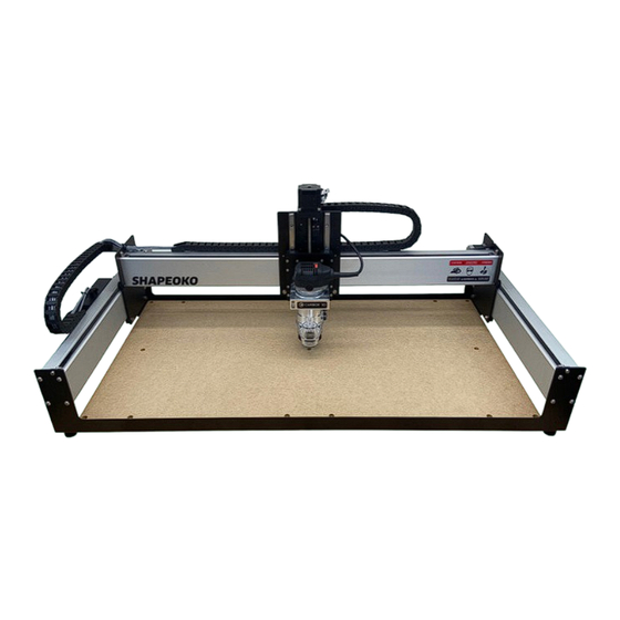
You are now the proud owner of the Shapeoko XL, an incredibly powerful and easy-to-use CNC machine. Welcome and Congratulations....................1 In this guide we will walk you step-by-step through the assembly of your Shapeoko XL. If you run into any Important Safety Instructions.....................2 problems along the way, send us an email at support@carbide3d.com... -
Page 3: Important Safety Instructions
Start Carbide Motion 5 on your computer. Turn the Shapeoko XL on by flipping the in-line rocker switch on the power supply cord to the ON position. Once Consider the possibility of a fire caused by friction from the router and take suitable fire prevention powered on, you will see a steady blue LED light on the Carbide Motion board through a slit in the enclosure precautions (e.g. -
Page 4: Step 1 Inventory
PRO TIP: Your Shapeoko XL kit has been carefully packaged by hand and double checked for accuracy. If, after completing your inventory, you find that something is missing or damaged, contact us at support@carbide3d.com and we’ll ship it to you ASAP. -
Page 5: Step 2 Baseframe
Y‑Axis Left Assembly & XL Final Assembly box contents; see Figure 1‑4: Y‑Axis Right Assembly Boxes Item Description Baseframe Hardware: M5 x 25mm Button Head Cap Screws (+3 Extra) Open the boxes labeled Y-Axis Right Assembly Baseframe Adjustable Leveling Feet and Y-Axis Left Assembly and visually verify they match the carriages shown in Figure 1‑3. -
Page 6: Step 6 Drag Chain
X/Z+ Box Sweepy Box This box should contain all the items listed in the The Sweepy Dust Boot is available for 65mm and table below and shown in Figure 1‑5. 69mm routers. Open the Sweepy box and verify you received the correct diameter. See Figure 1‑7. Figure 1-5 Figure 1-7 Item... - Page 7 Endplates Additional Required Tools The following tools are not included in your The two (2) endplates are identical. See Shapeoko kit, but are required for assembly. See Figure 1‑10. Figure 1‑13: Each endplate has eight (8) integrated PEM nuts. Inspect each nut to verify threads are properly Item Description formed and that it is seated squarely in place.
- Page 8 Required Components See Figure 2‑2: Item Description Location Step 2 Endplate MDF Baseplate Cross Strap Adjustable Leveling Foot XL Final Assembly Box Baseframe M5 x 25mm Button Head Cap Screw XL Final Assembly Box Required Tools See Figure 2‑3: Item Description 3mm Hex Key Level (not included) Recommended Tools See Figure 2‑3:...
- Page 9 Attach the MDF Baseplate Attach the Front Endplate 1. Lay the MDF baseplate over the three cross 1. Slide the remaining endplate UNDER all three straps, with the countersunk holes facing up. cross straps along the front of the baseframe and align the screw holes.
- Page 10 Required Components See Figure 3‑2: Step 3 Item Description Location X-Axis Aluminum Extrusion Rail (X-Rail) Y-Axis Left Assembly Box (empty) Y-Axis Right Assembly Box (empty) Carriages Y-Axis Left Carriage (Y1-Carriage) Y-Axis Left Assembly Box M6 x 12mm Button Head Cap Screw XL Final Assembly Box Z-Plus Carriage (Z-Plus) X/Z+ Box...
- Page 11 30mm standoffs pointing up. 3. Set the X-motor onto the four (4) evenly- spaced standoffs in the center of the Z-Plus, with the Carbide 3D label facing down (toward the idlers). See Figure 3‑8. 4. Use the 4mm hex key and four (4) M5x10mm socket head cap screws to secure the X-motor to the Z-Plus.
- Page 12 5. Grasp the sides of the Z-Plus with both hands and lower the Z-carriage with your thumbs The router mount attaches to the FRONT of the tramming plate with the Carbide 3D logo facing UP. until it stops at the bottom. See Figure 3‑13.
- Page 13 Install the Z‑Plus NOTE: Each extrusion rail has a pair of V-rails running the entire length of one side. 1. With the router mount facing front, line the These V-rails serve as linear tracks for the four V-wheels up with the two V-rails, and V-wheels, securing the carriages to the slide the Z-Plus onto the open end of the X-rail.
- Page 14 Required Components See Figure 4‑2: Item Description Location Step 4 Y-Axis Left Aluminum Extrusion Rail (Y1-Rail) M6 x 12mm Button Head Cap Screw XL Final Assembly Box Y-Axis Right Aluminum Extrusion Rail (Y2-Rail) M6 x 12mm Button Head Cap Screw XL Final Assembly Box Gantry Required Tools See Figure 4‑3:...
- Page 15 Insert the Y1‑Rail 1. Prop up the Y1-rail with the two foam packing blocks from the Y-Axis Left and Right Assembly boxes. See Figure 4‑8. WARNING: Be sure to insert the Y1-rail right- side up: M6 holes towards the REAR and the 2.
- Page 16 Required Components See Figure 5‑2: Item Description Location Step 5 Steel-Core Toothed Belt XL Final Assembly Box Belt Clip XL Final Assembly Box M5 x 10mm Socket Head Cap Screw XL Final Assembly Box Belting Required Tools See Figure 5‑3: Item Description 3 and 4mm Hex Key Ruler or Tape Measure (not included) Figure 5-3...
- Page 17 Install the X‑Rail Belt 6. Use the 3mm hex key to reach in between the X-motor and carriage plate, hook the loop, and 1. Attach a belt clip to one end of the longest pull it up and out towards you. See Figure 5‑8. belt.
- Page 18 11. Use the 4mm hex key and one (1) M5x10mm 5. Slide the 3mm hex key under the belt, between socket head cap screw to attach the belt clip the two idlers, and use it as a lever against the to the Y2-carriage.
- Page 19 Required Components See Figure 6‑2: Item Description Location Step 6 Wiring Harness (X-Axis Drag Chain & Y-Axis Drag Chain) XL Wiring Harness Box 1 *** *** *** X-AXIS DRAG CHAIN SUPPORT SYSTEM *** *** *** X-Axis Drag Chain Head Bracket XL Wiring Harness Box 1 Drag Chain M5 x 8mm Socket Head Cap Screw XL Wiring Harness Box 2...
- Page 20 Y1-carriage with four (4) M5x10mm socket head cap screws. However, to attach the Y-Axis drag chain head bracket to the Shapeoko XL, the top two (2) motor-mount screws will need to be replaced by two (2) longer M5x16mm socket head cap screws. Once replaced, the shorter screws will no longer be needed.
- Page 21 Install the Wiring Harness THE WIRING HARNESS The complete wiring harness consists of the Y-Axis drag chain, X-Axis drag chain, four stepper WARNING: Drag chains will only curl in one direction. Do not force the drag chain to bend; if it motor extension cables, two proximity switches with cables, and one proximity switch extension doesn’t curl easily, simply turn it over and try again.
- Page 22 3. Reach over the X-rail and lift the tail of the 6. Use the 2mm hex key and one (1) M3x4mm Y-Axis drag chain with your left hand and the flat head screw to secure the tail of the Y-Axis head with your right, as shown in Figure 6‑11.
- Page 23 Required Components See Figure 7‑2: Item Description Location Step 7 X-Axis Proximity Switch Plate XL Wiring Harness Box M3 x 18mm Socket Head Cap Screw XL Wiring Harness Box M5 x 8mm Socket Head Cap Screw XL Wiring Harness Box Cable tie XL Wiring Harness Box Proximity Switches Y-Axis Proximity Switch Plate...
- Page 24 The Y-Axis proximity switch exits the Y-Axis drag Switches chain at the Y1-carriage. It attaches to the Y-Axis The Shapeoko XL includes three inductive switch plate then mounts to the OUTSIDE of the proximity switches. The Z-Axis proximity switch is Y2-carriage.
-
Page 25: Step 8 Wiring
Required Components See Figure 8‑2: Item Description Location Step 8 Carbide Motion Board and Enclosure XL Final Assembly Box PCB Riser Board (Adapter) XL Final Assembly Box M6 x 12mm Button Head Cap Screw XL Final Assembly Box Enclosure Cover XL Final Assembly Box Wiring Thumb Screw XL Final Assembly Box... - Page 26 Install the PCB Riser Board 2. Bundle all seven cables together and direct them into the notch at the top of the enclosure. The PCB riser board is required to connect the 3. Re-install the enclosure cover. polarized 3-pin inductive proximity switches to the Carbide Motion board.
-
Page 27: Step 9 Cleanup
Required Components See Figure 9‑2: Item Description Location Step 9 Cable Tie Mounts XL Wiring Harness Box M4 x 6mm Socket Head Cap Screw XL Wiring Harness Box Cable Ties XL Wiring Harness Box Shapeoko Decal XL Final Assembly Box Cleanup Required Tools See Figure 9‑3: Item... - Page 28 Secure Loose Cables 2. Use five (5) cable ties to secure the cables to the five (5) cable tie mounts. See Figure 9‑7. The cable tie mounts have two attachment Secure Cables at the Y1‑Carriage points. When securing cables to the All seven (7) cables crossing the Y1-carriage, are center cable tie mount, only use the upper bundled into the circular cutout at the top of the...
- Page 29 Required Components See Figure 10‑2: Item Description Location Step 10 Compact Router Compact Router Box Cable Ties XL Wiring Harness Box #201 ¼-inch Square End Mill Cutter XL Final Assembly Box Sweepy Dust Boot Sweepy Box Compact Router Required Tools See Figure 10‑3: Item Description 4mm Hex Key...
- Page 30 Secure the Power Cord Install Sweepy Dust Boot 1. Fully seat the upper half of the dust boot onto NOTE: The router’s power cord can cause the router’s lower motor housing with the electromagnetic interference with the 36mm dust port facing forward and toggle the stepper motor extension cables and the USB quick release to tighten.
-
Page 31: Step 11 Level And Square
1. Double-check for level now at several different points across the machine: front-to-back, side-to-side, and diagonally. Adjust the four (4) leveling feet where necessary. On the following pages you will find helpful information to get you ready to use your Shapeoko XL. Confirm Tension of the V‑Wheels 1. -
Page 32: Connect To Power
4. Flip the in-line rocker switch on the power cord to 4. Flip the in-line rocker switch on the power cord the ON position to turn on the Shapeoko XL. to the ON position. You will hear the motors begin to hum and a blue LED on the Carbide 5. -
Page 33: Workholding
Use these ultra-low-profile Gator Tooth Clamps as a backstop, practice run before moving on to cutting projects. flexible, reliable way to hold down material to your Shapeoko XL. a side clamp, or a toe clamp. With over 30mm of lateral travel, The kit includes everything you need to add this system to your these beasts will hold your job down safely and securely. -
Page 34: Cutting Tutorials And Projects
The Star Wars Coaster Project is an excellent crash course on how to use your Shapeoko XL. The tutorial walks you through designing a simple set of coasters in Carbide Create and then executing the project with Carbide Motion.
Need help?
Do you have a question about the Shapeoko XL and is the answer not in the manual?
Questions and answers