Advertisement
Table of Contents
- 1 Table of Contents
- 2 Welcome and Congratulations
- 3 Parts of the Shapeoko HDM
- 4 Important Safety Instructions
- 5 Step 1: Unpack the Machine
- 6 Step 2: Install the Software
- 7 Step 3: Install the Bitsetter HDM
- 8 Step 4: Set up the Chiller
- 9 Step 5: Set up the Spindle
- 10 Step 6: Set up the Electronics
- 11 Step 7: Enable & Configure the Bitsetter HDM
- 12 Step 8: Control the Shapeoko HDM
- 13 Shapeoko HDM Maintenance
- 14 Tramming the HDM
- 15 Extras
- Download this manual
Advertisement
Table of Contents

Related Manuals for Carbide 3D Shapeoko HDM


Summary of Contents for Carbide 3D Shapeoko HDM
- Page 1 Shapeoko GETTING STARTED GUIDE...
-
Page 3: Table Of Contents
Step 5: Set Up the Spindle ....................12 Step 6: Set Up the Electronics .................... 13 Step 7: Enable & Configure the BitSetter HDM ..............14 Step 8: Control the Shapeoko HDM ................... 16 Shapeoko HDM Maintenance ..................... 18 Tramming the HDM ......................21 Extras ........................... -
Page 4: Welcome And Congratulations
Optical isolation and RS-422 serial connection for reduced electrical noise and static discharge. In this guide we’ll walk you through everything you need to know to get started using your Shapeoko HDM. If you encounter any issues setting up your machine, contact our tech support team at support@carbide3d.com... -
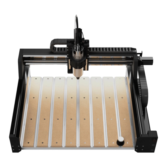
Page 5: Parts Of The Shapeoko Hdm
Parts of the Shapeoko HDM Coolant Tubes (2) Stepper Motors (4): Z, X, YL, YR Spindle Spindle Mount Drag Chains (2): X and Y Linear Rails (2 per Axis) Ballscrews (4): Z, X, YL, YR Drag Chain Support Panels (2) - Page 6 Variable Frequency Drive (VFD) Latches (2) Cable Channels (3) Power Switch Power Cord Jack — Outside Electronics Cabinet Fans (2) Variable Frequency Drive (VFD) 36V Power Supply Warthog Controller Electronics Cabinet — Inside docs.carbide3d.com...
-
Page 7: Important Safety Instructions
Important Safety Instructions The Shapeoko HDM is a machine tool and requires the same caution that should be exercised with any power tool. Please keep this manual in a safe place for reference. WARNING: To reduce risk of burns, fire, electric shock, injury, and death, or damage to equipment or property, read the following warnings carefully. - Page 8 Shut Off Machine When Not in Use Always power down the machine after each use: enable the spindle lock-out, disable the power to the machine, then turn off the power switch on the electronics cabinet. Wait 5–10 minutes, then shut off the chiller. Fire Prevention Never run the spindle with the chiller turned off.
-
Page 9: Step 1: Unpack The Machine
Lift from the front edge of the X-extrusion and the front end of the two Y-extrusions. See Fig. 1. Figure 1 Unbox the Shapeoko HDM To remove the machine from the packing crate: 1. Lift the sides of the packing crate to remove them. - Page 10 Unpack the Accessory Boxes Chiller Box Item Description CW-3000 Chiller Power Cord User Manual Accessories Box Item Description Electronics Cabinet Power Cord USB C-to-A Cable Sweepy 80mm V2 Dust Boot with Hose Adapters (3) #201 ¼” Square End Mill Precision Collets: ¼” and ”...
-
Page 11: Step 2: Install The Software
Check out the Carbide Motion User Guide: docs.carbide3d.com/assembly/carbidemotion/userguide. Carbide Create Carbide Create is a cross-platform 2D CAD/CAM software package made by Carbide 3D. This software is ideal for designing 2D and 2.5D parts, has built in 3D previews and works flawlessly with your machine. You’ll use Carbide Create to create 2D and 2.5D designs, generate toolpaths, and export G-code which you will run in Carbide... -
Page 12: Step 3: Install The Bitsetter Hdm
Step 3: Install the BitSetter HDM The BitSetter HDM is an automatic tool offset probe. It tracks the length of every tool installed in the spindle and updates the Z-zero position based on changes to the length of the tool. The BitSetter HDM will automatically measure the tool length in three circumstances: •... -
Page 13: Step 4: Set Up The Chiller
In the event of a malfunction, the chiller will display an error code on the LED screen. Error codes are listed in the included chiller manual. Contact the Carbide 3D tech support team at support@carbide3d.com assistance troubleshooting error codes. -
Page 14: Step 5: Set Up The Spindle
RPM based on the project G-code. The display screen on the VFD will show the spindle RPM during operation and error codes in the event of a malfunction. Contact the Carbide 3D tech support team at support@carbide3d.com for assistance troubleshooting error codes. -
Page 15: Step 6: Set Up The Electronics
Step 6: Set Up the Electronics The electronics cabinet contains the Warthog controller, power supply, and variable-frequency drive (VFD), which controls the water-cooled spindle. The Warthog controller uses the 36-volt power supply to power the motors and gantry. Warthog uses a combination of optical isolation and an RS-422 serial connection to the computer for increased immunity from electrical noise and static discharge. -
Page 16: Step 7: Enable & Configure The Bitsetter Hdm
Step 7: Enable & Configure the BitSetter HDM Setting Up the BitSetter HDM Home the Machine First, connect to and home the machine: 1. Power up your computer. 2. Connect the USB cable to the computer. 3. Start Carbide Motion. 4. - Page 17 In order for the BitSetter HDM to work, the post processor in Carbide Create must be correctly set: 1. In Carbide Create, go to Edit > Select Post Processor in the menu bar. 2. Select Carbide 3D Shapeoko. 3. In the Output Units dropdown list, select Metric or Inch.
-
Page 18: Step 8: Control The Shapeoko Hdm
Step 8: Control the Shapeoko HDM Machine-Control Buttons There are three machine-control buttons on the front-right endplate (see Fig. 4): 1. Feed Hold Button: Press and hold the button for momentary feed hold. Release the button to return to normal operation. When the button is pressed, Carbide Motion will open a dialog box letting you know that feed hold is activated. - Page 19 4. Load the G-code and the first tool, and set job zero. Ensure the spindle lock-out is engaged (the button LED will be off) before loading the first tool. 5. Turn on the chiller. 6. Press the Spindle Lock-Out button to enable the spindle (the red LED will turn on). 7.
-
Page 20: Shapeoko Hdm Maintenance
Shapeoko HDM Maintenance Recommended Oil We only recommend using Mobile Vactra No 2 oil on linear rails, ball bearing carriages (AKA guides or carriages), and ball screws. It should NOT be used on any other parts of the machine. Follow the safety guidelines provided with the oil. Wear gloves and safety glasses. - Page 21 4. Remove the small M4 grub screw in the center of each carriage. See Fig. 5. * Figure 5 5. Press the tip firmly into the screw hole and gently squeeze about 1ml of oil into each linear guide. See Fig.
- Page 22 6. Replace the M4 screws. 7. Apply a small amount of Vactra No 2 along the ball screw and linear rail (approximately 1–2ml). 8. Jog the axis the full length of travel a number of times at approximately 1000mm a min. 9.
-
Page 23: Tramming The Hdm
Tramming the HDM What is Tramming and Why Is it Important? Have you ever seen small tool marks on your projects or found that the audible pitch of the router/spindle changes significantly when cutting in a certain direction? If you are nodding to either of these, then you may need to tram your machine. - Page 24 Spindle is nodding backward. Spindle is nodding forward. The rear edge is cutting deepest. The front edge is cutting deepest. Spindle yaw is counterclockwise. Spindle yaw is clockwise. The left edge is cutting deepest. The right edge is cutting deepest. docs.carbide3d.com...
- Page 25 Tramming Once identified, it is easy enough to correct the tramming. Our entire Shapeoko range can be adjusted as needed. We recommend designing a basic square pocket surfacing toolpath for a small 2” × 2” square of stock and surface it using a ¼ end mill, with a depth of cut of 0.1mm (0.0039”), and a 6.35mm (¼”) step over. Adjusting Nod Nod should always be adjusted first.
-
Page 26: Extras
Extras Troubleshooting Guide PROBLEM POSSIBLE REASON HOW TO RESOLVE Power switch on the control cabinet is not Power on the control cabinet. turned on. Press the Machine Power button on the Power to the machine is disabled. front-right endplate (the blue button LED Machine will not will turn on). - Page 27 Machine Operating Checklist 1. Practice Safe Machining Always follow the safety guidelines listed at the beginning of this document. Always wear appropriate safety equipment, especially safety glasses/goggles and hearing protection. 2. Check the Machine Condition Check that all screws are tight; ballscrews, linear rails and guides, spindle, VFD, chiller, and extrusions are in good condition with no nicks or other damage;...
- Page 28 2. Load the new tool. 3. Click the Resume button in Carbide Motion. The BitSetter HDM will automatically measure the length of the new tool. 8. Set Job Zero Set job zero manually, or by using the probing sequence if you have a BitZero V1 or V2. If you wish to change the tool after setting job zero: 1.
- Page 29 Collet: A collet is a cone-shaped sleeve that holds an end mill in place in the spindle. End Mill / Cutter / Tool: End mills are the cutting tools used by the Shapeoko HDM. They come in several varieties, such as square, ball nose, and V-bit, and many sizes.
- Page 30 Jog: Move the spindle to a specific position (a set of X, Y, Z coordinates) in the work area. Spindle: The spindle is the part of the Shapeoko HDM that turns the end mills. The 80mm water-cooled spindle has an 8–24k RPM motor. It is controlled by the variable-frequency drive (VFD) and cooled by the closed-loop chiller.
- Page 31 support@carbide3d.com 12/18/2021 v1.0...
- Page 32 Carbide 3D 3630 Skypark Drive Torrance, CA 90505 310-504-3637 support@carbide3d.com facebook.com/carbide3d instagram.com/carbide3d...
Need help?
Do you have a question about the Shapeoko HDM and is the answer not in the manual?
Questions and answers