Table of Contents
Advertisement
Advertisement
Table of Contents

Related Manuals for Carbide 3D SHAPEOKO 3


Summary of Contents for Carbide 3D SHAPEOKO 3
-
Page 2: Table Of Contents
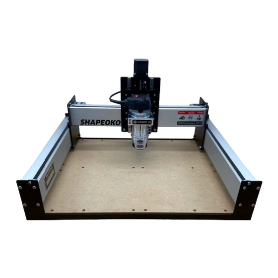
You are now the proud owner of the Shapeoko 3, an incredibly powerful and easy-to-use CNC machine. In this guide we will walk you step-by-step through the assembly of your Shapeoko 3. If you run into any Important Safety Instructions......................2 problems along the way, send us an email at support@carbide3d.com... -
Page 3: Important Safety Instructions
Start Carbide Motion 5 on your computer. Turn the Shapeoko 3 on by flipping the in-line rocker switch on the power supply cord to the ON position. Once Consider the possibility of a fire caused by friction from the router and take suitable fire prevention powered on, you will see a steady blue LED light on the Carbide Motion board through a slit in the enclosure precautions (e.g. -
Page 4: Step 1 Inventory
Carbide Compact Router Box Contains the Compact Router and Accessories/Tools Take Inventory PRO TIP: Your Shapeoko 3 kit was carefully Now, take a full inventory of all components using packaged by hand. If, after completing your the checklists on the following pages. Inspect items... - Page 5 Shapeoko 3 Final Assembly Box Shapeoko 3 Final Assembly box contents; see Figure 1‑4: Open the box labeled Shapeoko 3 Final Assembly and inspect its contents. Many parts are packaged in Item Description small plastic bags, and smaller bags may be packed into larger bags This box contains the items listed in the Baseframe Adjustable Leveling Feet table on the next page and shown in Figure 1‑4.
- Page 6 X/Z+ Box Endplates This box contains all the items listed in the table The two (2) endplates are identical. See Figure 1‑8. below and shown in Figure 1‑5. Each endplate has eight (8) integrated PEM nuts. Inspect each nut to verify threads are properly formed and that it is seated squarely in place.
- Page 7 Additional Required Tools Before You Begin Assembly The following tools are not included in your This guide contains many instructions with a Shapeoko kit, but are required for assembly. See directional reference, such as: left, right, front, Figure 1‑11: back, rear, inside, outside, etc. All such references are from the perspective of one Item Description...
-
Page 8: Step 2 Baseframe
See Figure 2‑2: Item Description Location Step 2 Endplate MDF Baseplate Adjustable Leveling Foot Shapeoko 3 Final Assembly Box M5 × 25mm Button Head Cap Screw Shapeoko 3 Final Assembly Box Baseframe Required Tools See Figure 2‑3: Item Description 3mm Hex Key... - Page 9 3 on the floor; a large workbench is essential. the MDF baseplate to the two endplates, six The completed dimensions of the Shapeoko 3 (6) screws for each endplate. See Figure 2‑7. are 28.5″ (X) × 24″ (Y) × 17.5″ (Z).
- Page 10 Y-Axis Right Assembly Box (empty) Carriages Y-Axis Left Carriage (Y1-Carriage) Y-Axis Left Assembly Box M6 × 12mm Button Head Cap Screw Shapeoko 3 Final Assembly Box Z-Plus Carriage (Z-Plus) X/Z+ Box Tramming Plate X/Z+ Box M5 × 8mm Socket Head Cap Screw...
- Page 11 Open the V‑Wheels ECCENTRIC NUTS AND V-WHEELS EXPLAINED 1. Gather the three (3) carriages. See Figure 3‑6: Eccentric nuts and V-wheels are what we use to adjust the gantry at the intersect between the carriage V-wheels and the V-rails. A loose connection here is referred to as carriage slop. To eliminate slop, a very small amount of tension is added a.
- Page 12 See Figure 3‑13. The router mount attaches to the FRONT of the tramming plate with the Carbide 3D logo facing UP. 1. Add one drop of Loctite 242 Threadlocker to the threads of the two (2) pocketed screw holes at the Figure 3-13...
- Page 13 Position the X‑Rail Install the Z‑Plus 1. With the router mount facing front, line the NOTE: Each extrusion rail has a pair of four V-wheels up with the two V-rails, and V-rails running the entire length of one side. slide the Z-Plus onto the open end of the X-rail. These V-rails serve as linear tracks for the See Figure 3‑17.
- Page 14 Step 4 Y-Axis Left Aluminum Extrusion Rail (Y1-Rail) M6 × 12mm Button Head Cap Screw Shapeoko 3 Final Assembly Box 8 Y-Axis Right Aluminum Extrusion Rail (Y2-Rail) M6 × 12mm Button Head Cap Screw Shapeoko 3 Final Assembly Box 8...
-
Page 15: Step 3 Carriages
Insert the Y1-Rail one front and one back. This creates a pivot point for rotating the Y2-rail up and into place. NOTE: The Y1-rail is plain, there are no 1. Prop up the Y1-rail with the two long foam threaded holes on either side of the rail. packing blocks from the X/Z+ box. -
Page 16: Step 5 Belting
Required Components See Figure 5‑2: Item Description Location Step 5 Steel-Core Toothed Belt Shapeoko 3 Final Assembly Box Belt Clip Shapeoko 3 Final Assembly Box M5 × 10mm Socket Head Cap Screw Shapeoko 3 Final Assembly Box Belting Required Tools See Figure 5‑3:... - Page 17 Install the X‑Rail Belt 7. Use the 3mm hex key to reach in between the X-motor and carriage plate, hook the loop, and 1. Select one of the three identical belts. pull it up and out towards you. See Figure 5‑8. 2.
- Page 18 12. Use the 4mm hex key and one (1) M5×10mm 5. Slide the 3mm hex key under the belt, between socket head cap screw to attach the belt clip the two idlers, and use it as a lever against the to the Y2-carriage.
- Page 19 Item Description Location Step 6 X-Axis Proximity Switch Shapeoko 3 Final Assembly Box 1 X-Axis Proximity Switch Plate Shapeoko 3 Final Assembly Box 1 M3 × 18mm Socket Head Cap Screw Shapeoko 3 Final Assembly Box 2 M5 × 8mm Socket Head Cap Screw...
- Page 20 Install the Y-Axis Proximity Switch The Y-Axis proximity switch has the shorter Switches cable. It attaches to the Y-Axis proximity switch The Shapeoko 3 has three inductive proximity mounting plate then attaches to the OUTSIDE of switches. The Z-Axis proximity switch is the Y2-carriage.
-
Page 21: Step 7 Wiring
Item Description Location Step 7 Carbide Motion Board and Enclosure Shapeoko 3 Final Assembly Box 1 PCB Riser Board (Adapter) Shapeoko 3 Final Assembly Box 1 M6 × 12mm Button Head Cap Screw Shapeoko 3 Final Assembly Box 2 Enclosure Cover... - Page 22 Install the PCB Riser Board WARNING: All connectors are polarized; they can only be connected in one way. Connecting The PCB riser board is required to connect the the wrong way will damage the machine. DO polarized 3-pin inductive proximity switches to the NOT FORCE A CONNECTION.
- Page 23 Connect the X- and Z- Cables Connect the Y-Axis Cables 1. Plug the Y1- and Y2-motor cables into the 1. Plug the X- and Z-motor cables into the corresponding connectors on the Carbide corresponding connectors on the Carbide Motion board labeled “Y1” and “Y2.” See Motion board labeled “X”...
- Page 24 See Figure 8‑2: Item Description Location Step 8 Compact Router Compact Router Box Cable Ties Shapeoko 3 Final Assembly Box #201 ¼-inch Square End Mill Cutter Shapeoko 3 Final Assembly Box Sweepy Dust Boot Sweepy Box Compact Router Required Tools See Figure 8‑3:...
- Page 25 Ensure this power cord to the two “standoff loops.” is accessible while the machine is running, in case you need to shut off the Shapeoko 3 7. Use a pair of flush cut pliers or scissors to trim immediately.
-
Page 26: Step 9 Level And Square
Square the Machine The machine is gradually brought into square by first loosening all structural support screws, then Step 9 tightening again while SIMULTANEOUSLY holding the X-rail parallel to the front and rear endplates. 1. Use the 4mm hex key to loosen all twenty-four (24) M6×12mm button head cap screws 1/2 turn back from snug (there are four (4) in the ends of Level and Square... - Page 27 Next Steps Download the Software On the following pages you will find helpful information to get you ready to use your Shapeoko 3. 1. Download Carbide Motion 5 from: carbide3d.com/carbidemotion/download. 1. Connect to Power 2. Download Carbide Create from: carbide3d.com/carbidecreate.
-
Page 28: Run The Test Project
Run the Test Project 2. Choose “Standard” from the Size dropdown list, “Z-Plus (Leadscrew)” from the Z-Axis Type dropdown list, and “Inches” or “MM” from the Units dropdown list. See Figure 11‑3. 3. Click the Update Shapeoko Configuration Required Components button in the middle of the dialog window. See Figure 11‑3. -
Page 29: Workholding
This concept is called workholding. There are several common ways to hold material down. The specifics of Star Wars Coaster Project is an excellent crash course on how to use your Shapeoko 3. The tutorial walks you through your project, part, material, and other requirements will determine which method you should use. The main objective for designing a simple set of coasters in Carbide Create and then executing the project with Carbide Motion. -
Page 30: Glossary Of Terms
Toolpath: A toolpath is the “route” the cutting tool will follow as it shapes the workpiece. We use Carbide Create, Carbide 3D’s cross-platform CAD/CAM program, to define the toolpaths for a project. Working Envelope: A working envelope is the CNC machine’s range of movement across each of its three axes, X, Y, and Z.
Need help?
Do you have a question about the SHAPEOKO 3 and is the answer not in the manual?
Questions and answers