Siemens SITRANS L Operating Instructions Manual
Radar transmitters with profibus pa
Hide thumbs
Also See for SITRANS L:
- Operating instructions manual (269 pages) ,
- Compact operating instructions (114 pages) ,
- Application examples (11 pages)
Table of Contents
Advertisement
Quick Links
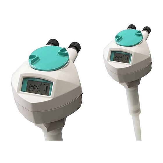
SITRANS LR200 with PROFIBUS PA
SITRANS L
Radar Transmitters
SITRANS LR200 with PROFIBUS PA
Operating Instructions
7ML5422 (Polypropylene rod antenna)
7ML5423 (Rod antenna)
7ML5425 (Horn antenna)
07/2021
A5E32337680-AF
Introduction
Safety notes
Description
Installing/mounting
Connecting
Operating
Parameter assignment
Service and maintenance
Diagnosing and
troubleshooting
Technical specifications
Dimension drawing
Product documentation and
support
Antenna options
Technical reference
PROFIBUS PA profile
structure
PROFIBUS communication
LCD menu structure
Abbreviations
1
2
3
4
5
6
7
8
9
10
11
A
B
C
D
E
F
G
Advertisement
Table of Contents
Troubleshooting

Related Manuals for Siemens SITRANS L


Summary of Contents for Siemens SITRANS L
- Page 1 SITRANS LR200 with PROFIBUS PA Introduction Safety notes Description SITRANS L Installing/mounting Connecting Radar Transmitters SITRANS LR200 with PROFIBUS PA Operating Parameter assignment Service and maintenance Operating Instructions Diagnosing and troubleshooting Technical specifications Dimension drawing Product documentation and support Antenna options...
- Page 2 Note the following: WARNING Siemens products may only be used for the applications described in the catalog and in the relevant technical documentation. If products and components from other manufacturers are used, these must be recommended or approved by Siemens. Proper transport, storage, installation, assembly, commissioning, operation and maintenance are required to ensure that the products operate safely and without any problems.
-
Page 3: Table Of Contents
Table of contents Introduction ............................11 Purpose of this documentation ..................11 Checking the consignment ....................11 Security information ......................12 Transportation and storage ....................12 Notes on warranty ......................13 Safety notes ............................14 Preconditions for safe use ....................14 Laws and directives ...................... - Page 4 Table of contents Connecting ............................33 Basic safety notes ......................33 Connecting SITRANS LR200 ....................35 5.2.1 Basic PLC configuration with PROFIBUS PA ................37 5.2.2 PLC configuration with PROFIFBUS PA for hazardous areas ..........38 Nameplates for hazardous area installations ............... 39 5.3.1 Device nameplate (ATEX/UKEX/IECEx/INMETRO) ..............
- Page 5 Table of contents 6.3.6.2 Set address ........................66 6.3.6.3 Echo profile utilities ......................66 6.3.6.4 Echo profile ........................67 6.3.6.5 View Saved Echo Profiles ....................67 6.3.6.6 Echo profile data logging ....................68 6.3.6.7 TVT Shaper ........................68 6.3.6.8 Auto false echo suppression ....................69 6.3.6.9 Echo Setup ........................
- Page 6 Table of contents 7.3.4.1 Volume (2.4.1.) ......................... 99 7.3.4.2 Vessel shape (2.4.1.1.) ...................... 99 7.3.4.3 Maximum volume (2.4.1.2.) .................... 100 7.3.4.4 Dimension A (2.4.1.3.)..................... 101 7.3.4.5 Dimension L (2.4.1.4.) ..................... 101 7.3.4.6 XY index (2.4.1.5.) ......................101 7.3.5 Signal processing (2.5.) ....................102 7.3.5.1 Near range (2.5.1.) ......................
- Page 7 Table of contents 7.5.2.4 Reminder activation (4.2.4.)..................... 124 7.5.2.5 Reminder 1 (required) (4.2.5.) ..................124 7.5.2.6 Reminder 2 (demanded) (4.2.6.) ..................124 7.5.2.7 Maintenance status (4.2.7.) ..................... 124 7.5.2.8 Acknowledge status (4.2.8.) .................... 125 7.5.2.9 Acknowledge (4.2.9.) ...................... 125 7.5.3 Remaining sensor lifetime (4.3.) ..................
- Page 8 Table of contents Service and maintenance ........................139 Maintenance and repair ....................139 8.1.1 Maintenance ........................139 Cleaning .......................... 140 Return procedure ......................140 Penetration of moisture into the device ................141 Disposal ........................... 141 Replacing the antenna ..................... 141 Diagnosing and troubleshooting .......................
- Page 9 Table of contents B.1.9 Raised-face flange markings ..................... 166 B.1.10 Flat-face flange (constant thickness series) ............... 167 B.1.11 Flat-face flange dimensions ..................... 168 B.1.12 Flat-face flange markings ....................169 B.1.13 Flange mounting instructions ..................170 B.1.14 PTFE tape......................... 171 B.1.15 Rod assembly ........................
- Page 10 Table of contents How the transducer block works ..................196 Analog Input Function Blocks 1 and 2 ................197 Output conversion ......................197 Device/input simulation ....................198 AIFB function groups ....................... 198 Analog Input Function Block function groups (simulation, mode and status) ..... 198 D.10 How an Analog Input Function Block works ..............
-
Page 11: Introduction
Introduction Purpose of this documentation These instructions contain all information required to commission and use the device. Read the instructions carefully prior to installation and commissioning. In order to use the device correctly, first review its principle of operation. The instructions are aimed at persons mechanically installing the device, connecting it electronically, configuring the parameters and commissioning it, as well as service and maintenance engineers. -
Page 12: Security Information
Siemens’ products and solutions undergo continuous development to make them more secure. Siemens strongly recommends that product updates are applied as soon as they are available and that the latest product versions are used. Use of product versions that are no longer supported, and failure to apply the latest updates may increase customer’s exposure to... -
Page 13: Notes On Warranty
The sales contract contains all obligations on the part of Siemens as well as the complete and solely applicable warranty conditions. Any statements regarding device versions described in the manual do not create new warranties or modify the existing warranty. -
Page 14: Safety Notes
Safety notes Preconditions for safe use This device left the factory in good working condition. In order to maintain this status and to ensure safe operation of the device, observe these instructions and all the specifications relevant to safety. Observe the information and symbols on the device. Do not remove any information or symbols from the device. -
Page 15: Fcc Conformity
Safety notes 2.2 Laws and directives 2.2.1 FCC Conformity US Installations only: Federal Communications Commission (FCC) rules Note • This equipment has been tested and found to comply with the limits for a Class A digital device, pursuant to Part 15 of the FCC Rules. These limits are designed to provide reasonable protection against harmful interference when the equipment is operated in a commercial environment. -
Page 16: Ce And Ukca Electromagnetic Compatibility (Emc) Conformity
2.2.4 Radio Equipment compliance (Europe and UK) Hereby, Siemens declares that the SITRANS LR200 is in compliance with the essential requirements and other relevant provisions of Directive 2014/53/EU and Regulation SI 2017/1206. The LR200 complies with EN 302 372 for use in closed storage vessels, when installed according to the installation requirements of EN 302 372, and may be used in all EU countries and the UK. -
Page 17: Conformity With European Directives
Safety notes 2.2 Laws and directives 2.2.5 Conformity with European directives The CE marking on the device symbolizes the conformity with the following European directives: Electromagnetic compatibil- Directive of the European Parliament and of the Council on the ity EMC harmonisation of the laws of the Member States relating to elec- 2014/30/EU tromagnetic compatibility... -
Page 18: Requirements For Special Applications
If you need additional information not covered by these instructions, contact your local Siemens office or company representative. Note Operation under special ambient conditions... -
Page 19: Lithium Batteries
Safety notes 2.4 Lithium batteries WARNING Loss of safety of device with type of protection "Intrinsic safety Ex i" If the device or its components have already been operated in non-intrinsically safe circuits or the electrical specifications have not been observed, the safety of the device is no longer ensured for use in hazardous areas. -
Page 20: Description
Description SITRANS LR200 Overview SITRANS LR200 is a 2-wire 6 GHz pulse radar level transmitter for continuous monitoring of liquids and slurries in storage vessels including high pressure and high temperature, to a range of 20 meters (66 feet). The instrument consists of an electronic component coupled to an antenna and either a threaded or flange type process connection. -
Page 21: Applications
SITRANS LR200 is very easy to install and configure via a graphical Human Machine Interface (HMI). You can modify the built in parameters either locally via the Siemens infrared handheld programmer, or from a remote location using one of the following options: •... -
Page 22: Installing/Mounting
Note Material compatibility Siemens can provide you with support concerning selection of parts wetted by process media. However, you are responsible for the selection of parts. Siemens accepts no liability for faults or failures resulting from incompatible materials. WARNING Unsuitable connecting parts Risk of injury or poisoning. - Page 23 Installing/mounting 4.1 Basic safety notes WARNING Pressure applications Danger to personnel, system and environment can result from improper installation. • Improper installation may result in loss of process pressure. CAUTION External stresses and loads Damage to device by severe external stresses and loads (e.g. thermal expansion or pipe tension).
-
Page 24: Mounting
Installing/mounting 4.2 Mounting WARNING Insufficient air supply The device may overheat if there is an insufficient supply of air. • Install the device so that there is sufficient air supply in the room. • Observe the maximum permissible ambient temperature. Refer to the information in the section Operating conditions (Page 151). -
Page 25: Nozzle Design
Installing/mounting 4.2 Mounting 4.2.1.1 Nozzle design • For nozzles 100 mm (4") in length or shorter use the 100 mm (4") shield. • For nozzles 250 mm (10") in length or shorter use the 250 mm (10") shield. The end of the shield section or end of the horn should protrude a minimum of 10 mm (0.4”) to avoid false echoes being reflected from the nozzle. -
Page 26: Nozzle Location
Installing/mounting 4.2 Mounting 4.2.1.2 Nozzle location Beam angle • Beam angle is the width of the cone where the energy density is half of the peak energy density. • The peak energy density is directly in front of and in line with the rod antenna. •... -
Page 27: Access For Programming
Installing/mounting 4.2 Mounting 4.2.1.3 Access for programming Provide easy access for viewing the display and programming via the handheld programmer. ① Ambient temperature (surrounding enclosure volume) -40 to +80 °C (-40 to +176 °F) ② Device nameplate ③ Process device tag ④... -
Page 28: Orientation In A Vessel With Obstructions
Installing/mounting 4.2 Mounting 4.2.1.4 Orientation in a vessel with obstructions Polarization reference point For best results on a vessel with obstructions, or a stillpipe with openings, orient the front or back of the device toward the obstructions. For an illustration, refer to Mounting on a stillpipe or bypass pipe (Page 28). - Page 29 Installing/mounting 4.2 Mounting Device orientation Bypass installation ① Vent ② Align front or back of device with vents ③ Optimum diameter 80 mm (3") Stillpipe installation ① Slots ② Align front or back of device with stillpipe slots SITRANS LR200 with PROFIBUS PA Operating Instructions, 07/2021, A5E32337680-AF...
-
Page 30: Installation
4.3 Installation Installation Siemens Level Transmitters with flanged, threaded, or sanitary clamp type process mounts have no pressure-bearing housing of their own and, therefore, do not come under the Pressure Equipment Directive as pressure or safety accessories, (see EU Commission Guideline 1/8). -
Page 31: Installation Instructions
Installing/mounting 4.3 Installation 4.3.1 Installation instructions Note • For pressure applications, it will be necessary to use PTFE tape or other appropriate thread sealing compound, and to tighten the process connection beyond hand-tight. • There is no limit to the number of times the device can be rotated without damage. •... -
Page 32: Disassembly
Installing/mounting 4.4 Disassembly Disassembly WARNING Incorrect disassembly The following risks may result from incorrect disassembly: - Injury through electric shock - Risk through emerging media when connected to the process - Risk of explosion in hazardous area In order to disassemble correctly, observe the following: •... -
Page 33: Connecting
Connecting Basic safety notes WARNING Unsuitable cables, cable glands and/or plugs Risk of explosion in hazardous areas. • Use only cable glands/plugs that comply with the requirements for the relevant type of protection. • Close unused cable inlets for the electrical connections. •... - Page 34 Connecting 5.1 Basic safety notes WARNING Unprotected cable ends Risk of explosion through unprotected cable ends in hazardous areas. • Protect unused cable ends in accordance with IEC/EN 60079-14. WARNING Improper laying of shielded cables Risk of explosion through compensating currents between hazardous area and the non-hazardous area.
-
Page 35: Connecting Sitrans Lr200
Connecting 5.2 Connecting SITRANS LR200 Connecting SITRANS LR200 Note • Check the nameplate on your instrument, to verify the approval rating. • Use appropriate conduit seals to maintain IP or NEMA rating. • See Device nameplate (ATEX/UKEX/IECEx/INMETRO) (Page 39). • Use a twisted pair cable: AWG 22 to 14 (0.34 mm to 2.5 mm •... - Page 36 Connecting 5.2 Connecting SITRANS LR200 If you want to rotate the enclosure, use the 2 mm Allen key to loosen the locking ring. 1. Strip the cable jacket for approximately 70 mm (2.75") from the end of the cable. 2. Thread the wires through the gland 3.
-
Page 37: Basic Plc Configuration With Profibus Pa
Connecting 5.2 Connecting SITRANS LR200 5.2.1 Basic PLC configuration with PROFIBUS PA ① Active PLC ② PDM on PC/laptop ③ DP/PA coupler ④ PROFIBUS DP ⑤ PROFIBUS PA ⑥ LR200 SITRANS LR200 with PROFIBUS PA Operating Instructions, 07/2021, A5E32337680-AF... -
Page 38: Plc Configuration With Profifbus Pa For Hazardous Areas
Connecting 5.2 Connecting SITRANS LR200 5.2.2 PLC configuration with PROFIFBUS PA for hazardous areas ① Active PLC ② PDM on PC/laptop ③ EEx ia type DP/PA coupler ④ Non-hazardous area ⑤ Hazardous area ⑥ EEx ia device SITRANS LR200 with PROFIBUS PA Operating Instructions, 07/2021, A5E32337680-AF... -
Page 39: Nameplates For Hazardous Area Installations
5.3.2 Device nameplate (FM/CSA) ① The FM/CSA Intrinsically Safe connection drawing number 23650529 can be downloaded from the product page of our website at LR200 (www.siemens.com/LR200). Go to Support > Approv- als/Certificates. • For wiring requirements: follow local regulations. •... - Page 40 Connecting 5.3 Nameplates for hazardous area installations Entity concept The Entity Concept allows interconnection of intrinsically safe apparatus to associated apparatus not specifically examined in such combination. The criteria for interconnection is that the voltage and current which intrinsically safe apparatus can receive and remain intrinsically safe, considering faults, must be equal to or greater than the output voltage (Uo) and output current (Io) levels which can be delivered by the associated apparatus, considering faults and applicable factors.
-
Page 41: Instructions Specific To Hazardous Area Installations
Connecting 5.4 Instructions specific to hazardous area installations Instructions specific to hazardous area installations 5.4.1 (Reference European ATEX Directive 2014/34/EU, Annex II, 1.0.6 and UK Regulation SI 2016/1107) The following instructions apply to equipment covered by certificate numbers SIRA 06ATEX2356X, SIRA 09ATEX4152X, CSAE 21UKEX2084X, and CSAE 21UKEX4083X: 1. - Page 42 Connecting 5.4 Instructions specific to hazardous area installations Specific conditions of use • Parts of the enclosure may be non-conducting and may generate an ignition-capable level of electrostatic charge under certain extreme conditions. The user should ensure that the equipment is not installed in a location where it may be subjected to external conditions (such as high-pressure steam), which might cause a build-up of electrostatic charge on non-conducting surfaces.
-
Page 43: Operating
Operating Basic safety notes DANGER Toxic gases and liquids Danger of poisoning when venting the device: if toxic process media are measured, toxic gases and liquids can be released. • Before venting ensure that there are no toxic gases or liquids in the device, or take the appropriate safety measures. -
Page 44: Local Operation
Operating 6.2 Local operation Local operation 6.2.1 Activating SITRANS LR200 Power up the instrument. SITRANS LR200 automatically starts up in Measurement mode. A transition screen showing the current firmware revision and an incrementing line of stars is displayed while the first measurement is being processed. Press Mode to toggle between Measurement and Program Mode. - Page 45 Operating 6.2 Local operation PROGRAM mode display Navigation view ① Item band ④ Current item number ② Menu bar ⑤ Current item ③ Current menu • A visible menu bar indicates the menu list is too long to display all items. •...
-
Page 46: Handheld Programmer
Operating 6.2 Local operation 6.2.3 Handheld programmer 6.2.3.1 (Part No. 7ML1930-1BK) The programmer is ordered separately. SITRANS LR200 with PROFIBUS PA Operating Instructions, 07/2021, A5E32337680-AF... -
Page 47: Key Functions In Measurement Mode
Operating 6.2 Local operation 6.2.3.2 Key functions in measurement mode Key functions in measurement mode Function Result Updates internal enclosure temperature New value is displayed in LCD secondary re- reading. gion. Updates echo confidence value. Updates distance measurement Mode opens PROGRAM mode Opens the menu level last displayed in this power cycle, unless power has been cycled since exiting PROGRAM mode or more than 2... -
Page 48: Parameter Menus
Operating 6.2 Local operation 6.2.5 Parameter menus Note For the complete list of parameters with instructions, see Parameter assignment (Page 90). Parameters are identified by name and organized into function groups. See LCD menu structure (Page 214). 1. QUICK START 2. - Page 49 Operating 6.2 Local operation 2. Navigating: key functions in Navigation mode Note • In Navigation mode ARROW keys move to the next menu item in the direction of the arrow. • For Quick Access to parameters via the handheld programmer, press Home , then enter the menu number, for example: 2.4.1.
- Page 50 Operating 6.2 Local operation The LCD returns to parameter view and displays the new selection. ① Parameter name ② Parameter number ③ Current selection 4. Changing a numeric value • Navigate to the desired parameter. • Press RIGHT arrow to open parameter view. The current value is displayed. •...
- Page 51 Operating 6.2 Local operation Key functions in edit mode Name Function UP or DOWN arrow Selecting Scrolls to item. options Numeric • Increments or decrements digits editing • Toggles plus and minus sign RIGHT arrow Selecting • Accepts the data (writes the parame- options ter) •...
-
Page 52: Quick Start Wizard Via The Handheld Programmer
Operating 6.2 Local operation 6.2.6 Quick Start Wizard via the handheld programmer 1. Quick Start 1.1. Quick Start Wiz • Point the programmer at the display from a maximum distance of 300 mm (1 ft), then press RIGHT arrow to activate PROGRAM mode and open menu level 1. •... - Page 53 Operating 6.2 Local operation Operating Mode ① Space ④ High Calibration Point (process full level) ② Level ⑤ Sensor reference point ③ Distance ⑥ Low Calibration Point (process empty level) Operation Description NO SERVICE Measurement and associated loop current are not updated, and the device defaults to Fail-safe mode.
-
Page 54: Auto False Echo Suppression
Operating 6.2 Local operation 6.2.7 Auto False Echo Suppression If you have a vessel with known obstructions, we recommend using Auto False Echo Suppression to prevent false echo detection. See TVT setup (2.5.10.) (Page 107) for instructions. This feature can also be used if SITRANS LR200 displays a false high level, or the reading is fluctuating between the correct level and a false high level. -
Page 55: Device Address
SIMATIC PDM is a software package used to commission and maintain SITRANS LR200 and other process devices. Please consult the operating instructions or online help for details on using SIMATIC PDM. You can find more information at www.siemens.com/simatic-pdm (www.siemens.com/simatic-pdm). SITRANS LR200 with PROFIBUS PA... -
Page 56: Functions In Simatic Pdm
Operating 6.3 Remote operation 6.3.2 Functions in SIMATIC PDM Note • For a complete list of parameters see Parameter assignment (Page 90). • While the device is in PROGRAM mode the output remains fixed and does not respond to changes in the device. SIMATIC PDM monitors the process values, alarms and status signals of the device. -
Page 57: Initial Setup
1. Check that you have the most recent EDD, and if necessary download it from the product page of our website at LR200 (www.siemens.com/LR200). Save the files to your computer, and extract the zipped file to an easily accessed location. Launch SIMATIC PDM – Manager Device Catalog, browse to the unzipped EDD file and select it. -
Page 58: Quick Start Wizard
HART and PROFIBUS PA devices with SIMATIC PDM can be downloaded from the product page of our website at: www.siemens.com/LR200 (www.siemens.com/LR200)). 3. Open the menu Device – Master Reset and click on OK to perform a reset to Factory Defaults. -
Page 59: Step 1 - Identification
Operating 6.3 Remote operation 6.3.4.2 Step 1 - Identification Note The layout of the dialog boxes shown may vary according to the resolution setting for your computer monitor. 1. Click on Read Data from Device to upload Quick Start parameter settings from the device to the PC/PG and ensure PDM is synchronized with the device. -
Page 60: Step 3 - Vessel Shape
Operating 6.3 Remote operation 6.3.4.4 Step 3 - Vessel Shape The vessel shapes shown are predefined. To describe a more complex shape see Using Linearization via the Quick Start Wizard (Page 62). For a vessel with obstructions, see Auto False Echo Suppression. (Page 69) Select the vessel shape and click on NEXT. -
Page 61: Step 4 - Range
Operating 6.3 Remote operation 6.3.4.5 Step 4 - Range Set the parameters, and click on NEXT. 6.3.4.6 Step 5 - Summary Check parameter settings, and click on BACK to return and revise values, FINISH to save settings offline, or FINISH AND DOWNLOAD to save settings offline and transfer them to the device. -
Page 62: Using Linearization Via The Quick Start Wizard
Operating 6.3 Remote operation Example (values for example purposes only) Break- Level Volume point no. value (m) value (l) 3000 19.5 8000 6.3.4.8 Using Linearization via the Quick Start Wizard Open the menu Device - Wizard - Quick Start: In Step 1 - Identification, click on Read Data from Device, select language, and click on Next. - Page 63 Operating 6.3 Remote operation ① Linearization • Enter parameter values. • Click on Linearization • In the Linearization window click on the appropriate Breakpoint tab to open the dialog window. , and click on OK. • Enter the desired level and associated volume values Note The Reset button resets values to the values in the offline table.
-
Page 64: Configuring A Stillpipe Application
Operating 6.3 Remote operation In Step 5 – Summary, check parameter values. Click on BACK to return and revise values, FINISH to save settings offline, or FINISH AND DOWNLOAD to save settings offline and transfer them to the device. The message Quick Start was successful will appear. Click on OK. 6.3.4.9 Configuring a stillpipe application •... -
Page 65: Changing Parameter Settings Using Simatic Pdm
Operating 6.3 Remote operation 6.3.5 Changing parameter settings using SIMATIC PDM 6.3.5.1 Changing parameter settings using SIMATIC PDM Note • For a complete list of parameters, see Parameter Reference (Page 90). • Clicking on Cancel during an upload from device to SIMATIC PDM will result in some parameters being updated. -
Page 66: Pull-Down Menus
Operating 6.3 Remote operation 6.3.6.1 Pull-down menus Device menus View menus Communication path Process variables (Page 77) Download the device Device diagnostics Upload to PC/PG Toolbar Update diagnostic status Device Status (Page 81) Set address (Page 66) Update (Page 82) Wizard - Quick start Echo profile utilities (Page 66) Maintenance (Page 73) -
Page 67: Echo Profile
Operating 6.3 Remote operation 6.3.6.4 Echo profile Note • Double click on each axis to see the Xscale and Data Scale values. Right-click or Left-click on the axis and drag to reposition the scale. • After saving a profile click on OK, not the x button, to close the Echo Profile Utilities window, otherwise the profile will not be saved. -
Page 68: Echo Profile Data Logging
Operating 6.3 Remote operation 6.3.6.6 Echo profile data logging You can store up to 60 profiles at a selected interval (maximum 60 minutes). Inside Echo Profile Utilities, in the Echo Profile Time Based Storage window: 1. Enter the desired interval between stored profiles. 2. -
Page 69: Auto False Echo Suppression
Operating 6.3 Remote operation • Click on Measure to refresh the echo profile and load the current TVT from the device. • Change the position of the cursor on the TVT using the Point+ and Point– buttons: raise and lower the TVT using Offset+ and Offset–. •... - Page 70 Operating 6.3 Remote operation 1. Make sure the material level is below all known obstructions. 2. Determine Auto False Echo Suppression Range. Measure the actual distance from the sensor reference point to the material surface using a rope or tape measure. Subtract 0.5 m (20") from this distance, and use the resulting value.
- Page 71 Operating 6.3 Remote operation Before Auto False Echo Suppression ① TVT Hover Level ④ Echo marker ② Default TVT ⑤ Material level ③ False echo After Auto False Echo Suppression ① False echo ④ Material level ② Learned TVT ⑤ Default TVT ③...
-
Page 72: Echo Setup
Operating 6.3 Remote operation 6.3.6.9 Echo Setup Provides quick access to echo profile parameters: ① Algorithm ⑤ CLEF Range ② Position Detect ⑥ Response Rate ③ Echo Threshold ⑦ Fill Rate/min. ④ Damping Filter ⑧ Empty Rate/min. SITRANS LR200 with PROFIBUS PA Operating Instructions, 07/2021, A5E32337680-AF... -
Page 73: Maintenance
Operating 6.3 Remote operation 6.3.6.10 Maintenance You can set schedules and reminders for: • device maintenance based on its projected lifetime • sensor maintenance based on its projected lifetime • service • calibration To set Device/Sensor Maintenance schedules: 1. Open the menu Device – Maintenance, and click on the Remaining Device/Sensor Lifetime tab. -
Page 74: Acknowledge Faults
Operating 6.3 Remote operation To set Service/Calibration schedules: 1. Open the menu Device – Maintenance, and click on the Service/Calibration Schedule tab. 2. Modify desired values and if desired, set reminders for either or both of Reminder 1 before Lifetime (Required)/Reminder 2 before Lifetime (Demanded). 3. - Page 75 Operating 6.3 Remote operation Simulate analog input to AIFB1 and AIFB2 Allows you to input a simulated measured value, status, and quality, in order to test the functioning of an Analog Input Function Block. 1. Open the menu Device – Simulation, and select the desired function block. 2.
- Page 76 Operating 6.3 Remote operation Simulate input Allows you to simulate the sensor value which is input to the Level Transducer Block. This tests everything between the Level Transducer Block and Output. 1. Open the menu Device – Simulation, and select Simulation (Input). 2.
-
Page 77: Process Variables
Operating 6.3 Remote operation 6.3.6.14 Process variables To compare outputs in real time open the menu View – Process Variables and click on Overview to see reading (level, space, distance, volume); analog output; device status; and current electronics temperature. To see highest and lowest electronics temperatures, navigate to Level Meter > Maintenance and Diagnostics >... - Page 78 Operating 6.3 Remote operation Function Blocks Open the menu View – Process Variables and click on Function Blocks to view the channel (level or distance), operating mode (Auto, Manual, or Out of Service), quality, status, simulation setting, and summary of alarms. Trend view Open the menu View –...
-
Page 79: Write Locking
Operating 6.3 Remote operation 6.3.6.15 Write Locking Prevents any changes to parameters via PDM or the hand-held programmer. If Write Locking is enabled, the data can be viewed but not modified. To enable/disable Write Protection: 1. Open the menu Device – Write Locking and turn Write Protection On or Off. 2. -
Page 80: Diagnostics
Operating 6.3 Remote operation To perform a reset to factory defaults: 1. Open the menu Device – Master Reset and click on OK to perform a reset to Factory Defaults. 2. After the reset is complete upload parameters to the PC/PG. (If you are performing a reset after replacing the device with a different instrument, do not upload parameters to the PC/PG). -
Page 81: Device Status
Operating 6.3 Remote operation 6.3.6.20 Device Status Open the menu View – Device Status to view Diagnostics, Device Status, Hardware/ Firmware (HW/FW) Status, and Maintenance status. ① Update diagnostics In the Diagnostics window, click on Update diagnostics to update diagnostic information and refresh linked icons. -
Page 82: Update
Operating 6.3 Remote operation 6.3.6.22 Update Open the menu View – Update to refresh the screen. 6.3.6.23 Security A password option protects security and communication control parameters from modification by a maintenance user. When you open a project the User dialog window provides two options: maintenance or specialist. -
Page 83: Application Examples
EDD is independent of the operating system. SITRANS DTM • SITRANS DTM is an EDDL interpreter developed by Siemens to interpret the EDD for that device. • To use SITRANS DTM to connect to an instrument, you must first install SITRANS DTM on your system and then install the instrument EDD written for SITRANS DTM. -
Page 84: Level Application Example
Operating 6.4 Application examples 6.4.2 Level application example The application is a vessel that takes an average 3 hours (180 minutes) to fill and 3 weeks to empty. Fill rate = 0.08 m/minute [(Low Cal Pt. minus High Cal Pt.) / fastest of fill or empty time] = (15.5 m –... -
Page 85: Liquid Resin In Storage Vessel, Level Measurement
Operating 6.4 Application examples 6.4.3 Liquid resin in storage vessel, level measurement Note • Minimum distance from flange face to target is limited by Near range (2.5.1.) (Page 102). • We recommend using Auto False Echo Suppression with an empty or almost empty vessel. To obtain level measurement/4 to 20mA output proportional to resin levels: •... -
Page 86: Liquid Resin In Storage Vessel
Operating 6.4 Application examples 6.4.4 Liquid resin in storage vessel Parameter Parameter name/No. Options/Values Function type Quick start Material (1.2.) LIQUID wizard parame- Response Rate (1.3.) Medium=1 m/minute ters Units (1.4.) meters Operating Mode (1.5.) LEVEL Level Low calibration point 5 m (16.4 ft) (1.6.) High calibration point... - Page 87 Operating 6.4 Application examples ① Sensor reference point ⑥ A=0.8 m ② 0.5 m ⑦ L=6 m ③ High calibration point ⑧ Volume reading ④ 3.5 m ⑨ 100%=8000 L ⑤ Low calibration point Parameter Parameter name/No. Options/Values Function type Quick start Material (1.2.) LIQUID...
-
Page 88: Application With Stillpipe
Operating 6.4 Application examples 6.4.6 Application with stillpipe A stillpipe is recommended for products with a dK of less than 3, or if extremely turbulent or vortex conditions exist. This mounting arrangement can also be used to provide optimum signal conditions on foaming materials. Note •... -
Page 89: Stillpipe Table
Operating 6.4 Application examples 6.4.7 Stillpipe table Parameter Parameter no./name Options/Values Function type Quick start Material (1.2.) LIQUID LOW DK wizard Response Rate (1.3.) Medium =1 m/minute Units (1.4.) meters Operating Mode (1.5.) LEVEL Level is reported as Volume when a vessel shape is selected. -
Page 90: Parameter Assignment
Parameter assignment Parameter reference Note • Parameter names and menu structure are almost identical for SIMATIC PDM and the local display interface (LDI). • To enter Program mode using the device buttons, press . Press to return to Measurement mode. •... -
Page 91: Quick Start (1.)
Parameter assignment 7.2 Quick start (1.) Quick start (1.) The Quick Start wizard provides an easy step-by-step procedure to configure the device for a simple application. From measurement screen, press RIGHT arrow twice to open the Quick Start Wizard menu. Select a wizard, press RIGHT arrow to open the first step, and follow the instructions. -
Page 92: Setup (2.)
Parameter assignment 7.3 Setup (2.) Setup (2.) 7.3.1 Identification (2.1) 7.3.1.1 Identification (2.1.) 2.1.1. Tag Text that can be used in any way. A recommended use is as a unique label for a field device in a plant. Limited to 32 ASCII characters. Note SITRANS PDM limits the TAG field to a maximum of 24 characters. -
Page 93: Sensor (2.3.)
Parameter assignment 7.3 Setup (2.) 7.3.3 Sensor (2.3.) 7.3.3.1 Units (2.3.1.) Description sensor measurement units Options m, cm, mm, ft, in Factory setting 7.3.3.2 Level unit (2.3.2.) Description Select engineering units for Level. Options m, cm, mm, ft, in, % Factory setting 7.3.3.3 PV units (volume/level) (2.3.3.) -
Page 94: Material (2.3.5.)
Parameter assignment 7.3 Setup (2.) 7.3.3.5 Material (2.3.5.) Description Automatically configures the device to operate in the chosen application type, by changing one or more of the following parameters: Propagation Factor, Posi- tion Detect, and/or CLEF Range. Options LIQUID LIQUID LOW DK (low dielectric liquid - CLEF algorithm enabled Factory setting LIQUID... - Page 95 Parameter assignment 7.3 Setup (2.) Low calibration point (2.3.7.1.) Description to Low Calibration Point. Units are de- Distance from sensor reference point fined in Units. Values 0 to 20 m Factory setting 20.00 m Related Far range (2.5.2.) (Page 103) parameters Units (2.3.1.) (Page 93) ①...
- Page 96 Parameter assignment 7.3 Setup (2.) Sensor offset (2.3.7.3.) Description Sensor Offset is a constant offset that can be added to or subtracted from sensor value to compensate if the sensor reference point has shifted. For example, this could result from adding a thicker gasket or reducing the standoff/nozzle height. The units are defined in Units (2.3.1.) (Page 93).
-
Page 97: Rate (2.3.8.)
Parameter assignment 7.3 Setup (2.) 7.3.3.8 Rate (2.3.8.) Response rate (2.3.8.1.) Response Rate sets the reaction speed of the device to measurement changes. Use a setting just faster than the maximum filling or emptying rate (whichever is greater). Note Changing Response Rate resets Fill rate/min (2.3.8.2.) (Page 97), Empty rate/min (2.3.8.3.) (Page 98) and Filter time constant (2.6.8.1.) (Page 114). - Page 98 Parameter assignment 7.3 Setup (2.) Empty rate/min (2.3.8.3.) Empty rate defines the maximum rate at which the reported sensor value is allowed to increase. Allows you to adjust the device's response to increases in the actual material level. Empty rate is automatically updated whenever Response rate (2.3.8.1.) (Page 97) is altered. Note Enter a value slightly greater than the maximum vessel-emptying rate, in units per minute.
-
Page 99: Linearization (2.4.)
Parameter assignment 7.3 Setup (2.) 7.3.4 Linearization (2.4.) 7.3.4.1 Volume (2.4.1.) Carries out a volume conversion from a level value. 7.3.4.2 Vessel shape (2.4.1.1.) Defines the vessel shape and allows the LR200 to calculate volume instead of level. If None is selected, no volume conversion is performed. -
Page 100: Maximum Volume (2.4.1.2.)
Parameter assignment 7.3 Setup (2.) Vessel shape LCD Display/ Also required description HALF SPHERE BOTTOM maximum volume, dimension A FLAT SLOPED BOTTOM maximum volume, dimension A PARABOLIC ENDS maximum volume, dimension A, Parabolic end horizontal dimension L cylinder LINEAR TABLE maximum volume, tables 1-32 Linearization table (lev- level and volume breakpoints... -
Page 101: Dimension A (2.4.1.3.)
Parameter assignment 7.3 Setup (2.) 7.3.4.4 Dimension A (2.4.1.3.) Description The height of the vessel bottom when the bottom is conical, pyramidal, parabol- ic, spherical, or flat -sloped. If the vessel is horizontal with parabolic ends, the depth of the end. For an illustration, refer to Vessel shape (2.4.1.1.) (Page 99). Values 0.0000 to 999999 mm in Level Units Factory setting... -
Page 102: Signal Processing (2.5.)
Parameter assignment 7.3 Setup (2.) To enter breakpoints via the handheld programmer: 1. The default for level values is percent: if you want to select units instead, navigate to Setup (2.) > Sensor (2.3.) > Level Unit (2.3.2.), and select the desired unit. 2. -
Page 103: Far Range (2.5.2.)
Parameter assignment 7.3 Setup (2.) 7.3.5.2 Far range (2.5.2.) Description Allows the material level to drop below Low Calibration Point without generat- ing a Loss of Echo (LOE) state. Use this feature if the measured surface can drop below the Low Cal. Point in normal operation. For an illustration, refer to Low calibration point (2.3.7.1.) (Page 95). -
Page 104: Maximum Sensor Value (2.5.5.)
Parameter assignment 7.3 Setup (2.) 7.3.5.5 Maximum sensor value (2.5.5.) The maximum recorded Sensor value in units defined in Unit (2.3.1.). • Open the menu View – Device Diagnostics, select Device Status, and click on the Device Status tab. • Check Sensor Peak Values 7.3.5.6 Shots (2.5.6.) The number of echo profile samples averaged to produce a measurement. - Page 105 Parameter assignment 7.3 Setup (2.) Echo threshold (2.5.7.3.) Description Sets the minimum echo confidence that the echo must meet in order to prevent a Loss of Echo condition and the expiration of the LOE timer. When Confidence (2.5.9.1.) (Page 107) exceed Echo Threshold, the echo is accepted as a valid echo and is evaluated.
-
Page 106: Sampling (2.5.8.)
Parameter assignment 7.3 Setup (2.) 7.3.5.8 Sampling (2.5.8.) Sampling provides a method of checking the reliability of a new echo before accepting it as the valid reading, based on numbers of samples above or below the currently selected echo. Echo lock (2.5.8.1.) Description Selects the measurement verification process. -
Page 107: Echo Quality (2.5.9.)
Parameter assignment 7.3 Setup (2.) 7.3.5.9 Echo quality (2.5.9.) Confidence (2.5.9.1.) Description Indicates echo reliability: higher values represent better echo quality. The display shows the echo confidence of the last measurement. Echo threshold (2.5.7.3.) (Page 105) defines the minimum criterion for echo confidence. Values (view 0 to 99 only) - Page 108 Parameter assignment 7.3 Setup (2.) Before Auto False Echo Suppression ① TVT Hover Level ② Default TVT ③ False echo ④ Material level ⑤ Echo marker 1. Determine Auto False Echo Suppression Range. Measure the actual distance from the sensor reference point to the material surface using a rope or tape measure.
- Page 109 Parameter assignment 7.3 Setup (2.) To set Auto False Echo Suppression via SIMATIC PDM: Open the menu Device – Echo Profile Utilities and click on the tab Auto False Echo Suppression. For more detailed instructions, refer to Auto false echo suppression (Page 69). To set Auto False Echo Suppression via the handheld programmer: Options Default TVT will be used...
-
Page 110: Tvt Shaper (2.5.11.)
Parameter assignment 7.3 Setup (2.) Shaper mode (2.5.10.4.) Description Enables/disables the TVT shaper. Options OFF (factory setting) 7.3.5.11 TVT shaper (2.5.11.) Breakpoint 1-9 (2.5.11.1.) Values Range: –50 to 50 dB Factory setting 0 dB Breakpoint 10-18 (2.5.11.2.) Values Range: –50 to 50 dB Factory setting 0 dB Breakpoint 19-27 (2.5.11.3.) -
Page 111: Mode (2.6.2.)
Parameter assignment 7.3 Setup (2.) 7.3.6.2 Mode (2.6.2.) Used to request an operating mode from the Analog Input Function Block. Options Automatic Mode (AUTO) Manual Mode (MAN) Out of Service (O/S) Allows you to put the SITRANS LR200 into Out of Service Mode and then reset it to Automatic Mode. -
Page 112: Input Scaling (2.6.5.)
Parameter assignment 7.3 Setup (2.) 7.3.6.5 Input scaling (2.6.5.) Upper value (2.6.5.1.) Factory setting: 100% Setting range: Range: -999999 to 999999 Purpose: Defines the operational upper range value of the input value (Process Value Scale) in PV (volume/level) Units. Process Value Scale normalizes the input value to a customer-defined range. -
Page 113: Alarms And Warnings (2.6.7.)
Parameter assignment 7.3 Setup (2.) Lower value (2.6.6.2.) Factory setting: Setting range: Range: -999999 to 999999 Purpose: Defines the operational lower range value of the output value in AIFB1 units. 7.3.6.7 Alarms and warnings (2.6.7.) High limit alarm (2.6.7.1.) Factory setting: Setting range: Range: -999999 to 999999 Purpose:... -
Page 114: Display (2.6.8.)
Parameter assignment 7.3 Setup (2.) Limit hysteresis (2.6.7.5.) Hysteresis is used to adjust the sensitivity of the trigger for alarm messages. It is used to compensate when a process variable fluctuates around the same value as a limit. A high level alarm occurs when a value exceeds an upper limit. -
Page 115: Fail-Safe Mode (2.6.9.)
Parameter assignment 7.3 Setup (2.) Decimal point (2.6.8.4.) Factory setting: Setting range: Range: 0, 1, 2, 3, 4, 5, 6, 7 Purpose: The number of digits to display after the decimal point. (The LCD is limited to displaying two decimal places in Measurement mode. In SIMATIC PDM, up to seven decimal places may be used to display meas- ured values.) 7.3.6.9... -
Page 116: Aifb2 (2.7.)
Parameter assignment 7.4 Diagnostics (3.) 7.3.7 AIFB2 (2.7.) See AIFB1 (2.6.) (Page 110): the parameters for AIFB2 are identical. 7.3.8 Measured values (2.8.) Read only. Allows you to view measured values for diagnostic purposes. In SIMATIC PDM, open the menu View - Process Variables. MAIN OUPUT (PV-Primary Value) (2.8.1.) The value for level, or volume (if volume conversion is selected). -
Page 117: Fault Reset (3.2.)
Parameter assignment 7.4 Diagnostics (3.) 7.4.2 Fault reset (3.2.) Clears the following faults: Fault code Description Device Lifetime Reminder 1 (Maintenance Required) Device Lifetime Reminder 2 (Maintenance Demanded) Sensor Lifetime Reminder 1 (Maintenance Required) Sensor Lifetime Reminder 2 (Maintenance Demanded) Device Service Reminder 1 (Maintenance Required) Device Service Reminder 2 (Maintenance Demanded) Internal Temperature High... -
Page 118: Enable (3.4.1.)
Parameter assignment 7.4 Diagnostics (3.) 7.4.5 Enable (3.4.1.) Note When cyclic communication is in progress, Condensed Status Mode cannot be changed. Options NO (disabled) YES (enabled) Select Yes or No to enable/disable Condensed Mode. 7.4.6 Features supported (3.4.2.) Read only. Features supported are: •... -
Page 119: Allocation (3.5.)
Parameter assignment 7.4 Diagnostics (3.) 7.4.8 Allocation (3.5.) 7.4.8.1 Event index (3.5.1.) The numeric component of the Event Code for a Condensed Status event. Use the index number to identify a particular event in the list below. Event index Event code Event description Loss of Echo No Tech Power... -
Page 120: Event Status (3.5.2.)
Parameter assignment 7.4 Diagnostics (3.) 7.4.8.2 Event status (3.5.2.) Event Status allows you to assign one of the status options listed below, to any of the events listed in Event Index (3.5.1.). This allows you to tailor a device response appropriate for your particular process. -
Page 121: Peak Values (3.6.)
Parameter assignment 7.4 Diagnostics (3.) To assign a diagnosis to a particular event via the handheld programmer: 1. Go to Enable (3.4.1.) and select Yes to enable Condensed Mode. 2. Go to Event Index (3.5.1.) and enter the event index number corresponding to a particular event. -
Page 122: Service (4.)
Parameter assignment 7.5 Service (4.) Service (4.) 7.5.1 Master reset (4.1.) Note Following a Factory Reset, some degree of reprogramming may be required, depending on the option chosen below. Reset options Result Factory defaults Resets all user parameters to the manufacturer’s default settings, with certain exceptions. -
Page 123: Remaining Device Lifetime (4.2.)
Parameter assignment 7.5 Service (4.) 7.5.2 Remaining device lifetime (4.2.) Note • Four sets of parameters allow you to monitor the Device/Sensor Lifetimes and set up Maintenance/Service schedules, based on operating hours instead of a calendar-based schedule, see Remaining sensor lifetime (4.3.) (Page 126), Service schedule (4.4.) (Page 129), and Calibration schedule (4.5.) (Page 132). -
Page 124: Time In Operation (4.2.2.)
Parameter assignment 7.5 Service (4.) 7.5.2.2 Time in operation (4.2.2.) Read only. The amount of time the sensor has been operating. 7.5.2.3 Remaining lifetime (4.2.3.) Read only. Lifetime expected (4.2.1.) (Page 123) less Time in operation (4.2.2.) (Page 124). 7.5.2.4 Reminder activation (4.2.4.) Factory setting: Setting range:... -
Page 125: Acknowledge Status (4.2.8.)
Parameter assignment 7.5 Service (4.) 7.5.2.8 Acknowledge status (4.2.8.) Indicates which level of maintenance reminder has been acknowledged. In SIMATIC PDM, open the menu Diagnostics > Device Diagnostics, click on the Maintenance tab, and check the Calibration Schedule Status window. 7.5.2.9 Acknowledge (4.2.9.) Purpose:... -
Page 126: Remaining Sensor Lifetime (4.3.)
Parameter assignment 7.5 Service (4.) 7.5.3 Remaining sensor lifetime (4.3.) Note • Four sets of parameters allow you to monitor the Device/Sensor Lifetimes and set up Maintenance/Service schedules, based on operating hours instead of a calendar-based schedule, see Remaining device lifetime (4.2.) (Page 123), Service schedule (4.4.) (Page 129), and Calibration schedule (4.5.) (Page 132). -
Page 127: Time In Operation (4.3.2.)
Parameter assignment 7.5 Service (4.) 7.5.3.2 Time in operation (4.3.2.) Read only. The amount of time the sensor has been operating. 7.5.3.3 Remaining lifetime (4.3.3.) Read only. Lifetime expected (4.3.1.) (Page 126) less Time in operation (4.3.2.) (Page 127). 7.5.3.4 Reminder activation (4.3.4.) Factory setting: Setting range:... -
Page 128: Acknowledge Status (4.3.8.)
Parameter assignment 7.5 Service (4.) 7.5.3.8 Acknowledge status (4.3.8.) Indicates which level of maintenance reminder has been acknowledged. In SIMATIC PDM, open the menu Diagnostics > Device Diagnostics, click on the Maintenance tab, and check the Calibration Schedule Status window. 7.5.3.9 Acknowledge (4.3.9.) Purpose:... -
Page 129: Service Schedule (4.4.)
Parameter assignment 7.5 Service (4.) 7.5.4 Service schedule (4.4.) Note • Four sets of parameters allow you to monitor the Device/Sensor Lifetimes and set up Maintenance/Service schedules, based on operating hours instead of a calendar-based schedule, see also Remaining sensor lifetime (4.3.) (Page 126), Remaining device lifetime (4.2.) (Page 123), and Calibration schedule (4.5.) (Page 132). -
Page 130: Time Since Last Service (4.4.2.)
Parameter assignment 7.5 Service (4.) 7.5.4.2 Time since last service (4.4.2.) Time elapsed since last service. Can be reset to zero after performing a service. Can be reset locally by entering 0 in this parameter. To reset to zero: • In SIMATIC PDM, open the menu Device – Maintenance, click on the Service Schedule tab, and click on Service Performed to restart the timer and clear any fault messages. -
Page 131: Reminder 2 (Demanded) (4.4.6.)
Parameter assignment 7.5 Service (4.) 7.5.4.6 Reminder 2 (demanded) (4.4.6.) Factory setting: 0.019 years Setting range: 0 to 20 years Purpose: If Time until next service (4.4.3.) (Page 130) is equal to or less than this value, the device generates a Maintenance Demanded reminder. Description: 1. -
Page 132: Calibration Schedule (4.5.)
Parameter assignment 7.5 Service (4.) 7.5.5 Calibration schedule (4.5.) Note • Four sets of parameters allow you to monitor the Device/Sensor Lifetimes and set up Maintenance/Service schedules, based on operating hours instead of a calendar-based schedule, see also Remaining device lifetime (4.2.) (Page 123), Remaining sensor lifetime (4.3.) (Page 126), and Service schedule (4.4.) (Page 129). -
Page 133: Time Since Last Calibration (4.5.2.)
Parameter assignment 7.5 Service (4.) 7.5.5.2 Time since last calibration (4.5.2.) Time elapsed since last calibration. Can be reset to zero after performing a calibration. Can be reset locally by entering 0 in this parameter. To reset to zero: • In SIMATIC PDM, open the menu Device – Maintenance, click on the Calibration Schedule tab, and click on Calibration Performed to restart the timer and clear any fault messages. -
Page 134: Reminder 2 (Demanded) (4.5.6.)
Parameter assignment 7.5 Service (4.) 7.5.5.6 Reminder 2 (demanded) (4.5.6.) Factory setting: 0.019 years Setting range: 0 to 20 years Purpose: If Time until next calibration (4.5.3.) (Page 133) is equal to or less than this value, the device generates a Maintenance Demanded reminder. Description: 1. -
Page 135: Power-On Resets (4.8.)
Parameter assignment 7.5 Service (4.) 7.5.8 Power-on resets (4.8.) The number of power cycles that have occurred since manufacture. In SIMATIC PDM, open the menu View – Wear. 7.5.9 LCD fast mode (4.9.) Description Enables a faster rate of measurement from the device by disabling most of the display area. -
Page 136: Communication (5.)
STD PROFILE Standard Profile (uses generic GSD for 2 AIFB [ident # = 0x9701] MANUFACTURER Manufacturer-specific (uses Siemens EDD and GSD file, which identifies the LR200 [PROFIBUS PA]) [ident # = 0x8150] STD – AIFB 1 ONL. Standard Profile AIFB 1 only (uses generic GSD for 1 AIFB) -
Page 137: Security (6.)
Parameter assignment 7.7 Security (6.) Security (6.) 7.7.1 Remote access (6.1.) 7.7.1.1 Remote lockout (6.1.1.) Description Enables or disables programming via the network and PDM. Options OFF (remote operation enabled) ON (remote operation disabled Factory setting Note If access control is changed to limit remote access, it can be reset only via the handheld programmer. -
Page 138: Language (7.)
Parameter assignment 7.8 Language (7.) Language (7.) Description Selects the language to be used on the LCD. Options English (factory setting) Deutsch Français Español SITRANS LR200 with PROFIBUS PA Operating Instructions, 07/2021, A5E32337680-AF... -
Page 139: Service And Maintenance
• Remove the instrument from service and wipe the antenna clean using a cloth and suitable cleaning solution. WARNING Impermissible repair of the device • Repair must be carried out by Siemens authorized personnel only. SITRANS LR200 with PROFIBUS PA Operating Instructions, 07/2021, A5E32337680-AF... -
Page 140: Cleaning
To return a product to Siemens, see Returns to Siemens (www.siemens.com/returns-to- siemens). Contact your Siemens representative to clarify if a product is repairable, and how to return it. They can also help with quick repair processing, a repair cost estimate, or a repair report/cause of failure report. -
Page 141: Penetration Of Moisture Into The Device
Further information about devices containing batteries can be found at: Information about battery/product return (WEEE) (https://support.industry.siemens.com/cs/document/109479891/) Replacing the antenna • When a new antenna is installed the propagation factor will not change. • After replacing the antenna check the material level reported by the device against the actual material level, and if necessary use Sensor Offset (2.3.3.) (Page 96) to compensate. -
Page 142: Diagnosing And Troubleshooting
• Check the network to ensure the PCL is com- municating with the LR200. If you continue to experience problems, go to our website at: www.siemens.com/LR200 (www.siemens.com/LR200), and check the FAQs for SITRANS LR200, or contact your Siemens representative. SITRANS LR200 with PROFIBUS PA... -
Page 143: General Fault Codes
Adjust process conditions to minimize foam or other adverse conditions. • Correct configuration range. • If fault persists, contact your local Siemens representa- tive. S: 2 Unable to collect profile because of a power Repair required: contact your local Siemens representa- condition that is outside the operating range of tive. - Page 144 • Ensure settings for High Calibration Point and Low Calibration Point are different. S: 11 Internal temperature sensor failure. Repair required: contact your local Siemens representa- tive. S: 12 Internal temperature of device has exceeded • Relocate device and/or lower process temperature specifications: it is operating outside its tem- enough to cool device.
- Page 145 Meaning Corrective Action Icon S: 34 Factory calibration for the device has been lost. Replacement required: contact your local Siemens repre- sentative S: 35 Factory calibration for the device has been lost. Replacement required: contact your local Siemens repre- sentative S: 36 Unable to start microwave module.
-
Page 146: Device Status Icons
Diagnosing and troubleshooting 9.3 Device status icons Device status icons Icon Priority Meaning Level • Maintenance alarm • Measurement values are not valid • Maintenance warning: maintenance demanded immediately • Measured signal still valid • Maintenance required • Measured signal still valid •... -
Page 147: Operation Troubleshooting
Diagnosing and troubleshooting 9.4 Operation troubleshooting Operation troubleshooting Operating symptoms, probable causes, and resolutions. Symptom Cause Action Display shows level or target is out of range • check specifications • check Low calibration point (2.3.7.1.) (Page 95) • increase Confidence (2.5.9.1.) (Page 107) Display shows material build-up on antenna •... - Page 148 Diagnosing and troubleshooting 9.4 Operation troubleshooting Symptom Cause Action liquid surface vortexed • decrease Fill rate/min (2.3.8.2.) (Page 97) • relocate device to side pipe • increase confidence threshold in Echo threshold (2.5.7.3.) (Page 105) material filling • relocate SITRANS LR200 Reading response slow Fill rate/min (2.3.8.2.) (Page 97) •...
-
Page 149: Technical Specifications
Technical specifications 10.1 Performance Reference operating conditions according to IEC 60770-1 Ambient temperature +15 to +25 °C (+59 to +77 °F) Storage temperature +15 to +25 °C (+59 to +77 °F) Humidity 45% to 75% relative humidity Ambient pressure 860 to 1060 mbar g (86000 to 106000 N/m Measurement accuracy (measured in accordance with IEC 60770-1) Maximum measured error (including hysteresis and non-repeatability) From end of antenna to 600 mm (1.96... -
Page 150: Power
Interface Configuration remote Siemens SIMATIC PDM local Siemens infrared handheld programmer Display (local) graphic LCD with bar graph representing level Display quality will be degraded in temperatures below –25 °C (–13 °F) and above +65 °C (+149 °F). 10.4 Construction... -
Page 151: Operating Conditions
Technical specifications 10.5 Operating conditions Enclosure Construction aluminum, polyester powder-coated Conduit entry 2 x M20x1.5, or 2 x ½" NPT Ingress protec- Type 4X, Type 6, IP 67, IP68 tion Weight (excluding extensions) 100 mm threaded polypropylene rod antenna approx. 3.5 kg (7.7 lb) DN50/PN16 or 2"... -
Page 152: Process
Technical specifications 10.6 Process 10.6 Process Process temperature Polypropylene rod 40 to +80 °C (40 to +176 °F) PTFE rod or SS horn 40 to +200 °C (40 to +392 °F) Pressure (vessel) up to 40 bar, gauge (580 psi, gauge) The maximum temperature is dependent on the process connection, antenna materials, and vessel pressure. -
Page 153: Programmer Data - 7Ml1930-1Bk
Technical specifications 10.8 Programmer data - 7ML1930-1BK 10.8 Programmer data - 7ML1930-1BK Siemens Infrared IS (Intrinsically Safe) Handheld Programmer for hazardous and all other locations (battery is non-replaceable). Approvals CE and UKCA FM/CSA Class I, II, III, Div. 1, Gr. A to G T6 ATEX 1 GD Ex ia op is IIC T4 Ga Ex ia op is IIIC T135°C Da... -
Page 154: Dimension Drawing
Dimension drawing 11.1 Uni-construction polypropylene rod antenna ① 1/2 " NPT cable entry (or alternatively, ⑥ Mounting thread M20 cable gland) ② Threaded cover ⑦ Polypropylene rod antenna with integral mounting thread and shield ③ Enclosure/electronics ⑧ Shield length (internal) Standard: 100 mm (4") Option: 250 mm (10") ④... - Page 155 Dimension drawing 11.1 Uni-construction polypropylene rod antenna Threaded connection markings Threaded connection markings are found on the flat face/faces of the process connection. Serial number: a unique number allotted to each process connection, including the date of manufacture (MMDDYY) followed by a number from 001 to 999. SITRANS LR200 with PROFIBUS PA Operating Instructions, 07/2021, A5E32337680-AF...
-
Page 156: Product Documentation And Support
Entering a serial number 1. Open the PIA Life Cycle Portal (https://www.pia-portal.automation.siemens.com). 2. Select the desired language. 3. Enter the serial number of your device. The product documentation relevant for your device is displayed and can be downloaded. -
Page 157: Technical Support
In addition to our technical support, Siemens offers comprehensive online services at Service & Support (http://www.siemens.com/automation/serviceandsupport). Contact If you have further questions about the device, contact your local Siemens representative at Personal Contact (http://www.automation.siemens.com/partner). To find the contact for your product, go to "all products and branches" and select "Products &... -
Page 158: Antenna Options
• Process temperature and pressure capabilities are dependent upon information on the process device tag. Reference drawing listed on the tag is available on the product page of our website at LR200 (www.siemens.com/LR200), under More Info > Installation drawings > Level Measurement > Continous Radar > LR200. -
Page 159: Flange Adapter Versions
Antenna options B.1 Flange adapter versions Flange adapter versions B.1.1 Threaded connection, PTFE rod ① Nameplate ④ Stainless steel mounting thread ② Locking ring ⑤ PTEE rod antenna ③ Process device tag ⑥ Sensor reference point 17 mm (0.67") SITRANS LR200 with PROFIBUS PA Operating Instructions, 07/2021, A5E32337680-AF... -
Page 160: Pfte Rod Antenna, Flat-Face Flange
Antenna options B.1 Flange adapter versions B.1.2 PFTE rod antenna, flat-face flange For other flange dimensions and bolt hole sizing, refer to Flat-face flange dimensions (Page 168). ① Nameplate ④ PTEE rod antenna ② Locking ring ⑤ Sensor reference point ③... -
Page 161: Threaded Connection, Pfte Rod, External Shield
Antenna options B.1 Flange adapter versions B.1.3 Threaded connection, PFTE rod, external shield ① Nameplate ⑥ Stainless steel antenna shield (inactive length) ② Sensor reference point ⑦ Stainless steel mounting thread ③ Shield length ⑧ Process device tag SL=min. 100 mm (4") customer- specified ④... -
Page 162: Flat-Face Flange With Horn Antenna And Waveguide Extension
Antenna options B.1 Flange adapter versions B.1.4 Flat-face flange with horn antenna and waveguide extension Note More information • For other flange dimensions and bolt hole sizing, refer to Raised-face flange dimensions (Page 166) or Flat-face flange dimensions (Page 168). •... -
Page 163: Flanged Horn Dimensions
Antenna options B.1 Flange adapter versions B.1.5 Flanged horn dimensions Note • Signal amplitude increases with horn diameter, so use the largest practical size. • 80 mm (3") and 100 mm (4") are not recommended in vessels due to the wide beam/ poor performance. - Page 164 Antenna options B.1 Flange adapter versions ① Waveguide ⑤ Locking ring ② Diameter ⑥ Nameplate ③ Sensor reference point ⑦ Flange thickness: See Raised-Face Flange Di- mensions (Page 166) or Flat-Face Flange Di- mensions (Page 168) ④ Process device tag ⑧...
-
Page 165: Raised-Face Flange Per En 1092-1
Antenna options B.1 Flange adapter versions B.1.7 Raised-face flange per EN 1092-1 ① Enclosure mounting hole (4) ⑦ Flange thickness ② Bolt hole ⑧ Facing height 3 mm ③ Enclosure mounting hole circle diame- ⑨ Facing diameter ter 86.36 (3.40") ④... -
Page 166: Raised-Face Flange Dimensions
Serial number: a unique number allotted to each flange, including the date of manufacture (MMDDYY) followed by a number from 001 to 999 Flange series: the Siemens drawing identification Heat code: a flange material batch code identification Facing: defines RF option... -
Page 167: Flat-Face Flange (Constant Thickness Series)
Antenna options B.1 Flange adapter versions B.1.10 Flat-face flange (constant thickness series) For details, refer to Flat-face flange dimensions (Page 168). ① Bolt hole ⑤ 20 mm (0.80") nominal ② Enclosure mounting hole ⑥ Antenna mounting hole ③ Bolt hole circle ⑦... -
Page 168: Flat-Face Flange Dimensions
Antenna options B.1 Flange adapter versions B.1.11 Flat-face flange dimensions Pipe size Flange size Flange O.D. Bolt hole cir- Bolt hole ∅ Number of cle ∅ bolts 2" ASME 150 lb 6.0” 4.75” .7” 3" ASME 150 lb 7.5” 6.0” .75”... -
Page 169: Flat-Face Flange Markings
(MMDDYY) followed by a number from 001 to 999. Flange series: the Siemens drawing identification. Nominal size: the flange size followed by the hole pattern for a particular flange class. For example: •... -
Page 170: Flange Mounting Instructions
Antenna options B.1 Flange adapter versions B.1.13 Flange mounting instructions Note • The integral process seal MUST rest on the customer-supplied flange (see the detail below). • The straight/taper transition of the rod should extend past the nozzle/vessel opening. Add extensions as required ①... -
Page 171: Ptfe Tape
Antenna options B.1 Flange adapter versions B.1.14 PTFE tape Note Pressure applications For pressure applications, it will be necessary to use PTFE tape or other appropriate thread sealing compound, and to tighten the process connection beyond hand-tight. B.1.15 Rod assembly ①... -
Page 172: Rod Extension Requirements
150 mm (6”) 50 mm 100 mm >150 mm (6”) extension not required Consult Siemens Milltronics for assistance with nozzle sizes not listed. Shielded rod antennas are available for these applications. Mounting guidelines B.2.1 Nozzle design • The nozzle should be as short as possible. -
Page 173: Threaded Rod Antenna
Antenna options B.2 Mounting guidelines B.2.3 Threaded rod antenna 1.5” or 2” threaded process connections are available in three thread types: NPT, BSP, and G. ① PTFE ② 316 S.S. ③ Max. nozzle height 100 mm (4") ④ Min I.D. 100 mm (4") For smaller diameters use a shielded rod. -
Page 174: Waveguide Antenna
• Process temperature and pressure capabilities are dependent upon information on the process device tag. The reference drawing listed on the tag can be downloaded from our website at: www.siemens.com/LR200. ① Vent hole ② Minimum 80 mm (3") • Recommended for products with a dK lower than 3. -
Page 175: Horn With Waveguide Extensions
Antenna options B.2 Mounting guidelines B.2.6 Horn with waveguide extensions • Recommended for long nozzles with a small diameter. For example, if the nozzle is 100 mm (4”) in diameter and 460 mm (18”) in length), the rod antenna is not suitable due to interference from the nozzle. -
Page 176: Technical Reference
Technical reference Note Where a number follows the parameter name [for example, Master Reset (4.1.)] this is the parameter access number via the handheld programmer. See Parameter Reference (Page 90) for a complete list of parameters. Fail-safe Mode The purpose of the Fail-safe setting is to put the process into a safe mode of operation in the event of a fault or failure. -
Page 177: Principles Of Operation
Echo processing C.3.1 Process Intelligence The signal processing technology embedded in Siemens radar level devices is known as Process Intelligence. Process intelligence provides high measurement reliability regardless of the dynamically changing conditions within the vessel being monitored. The embedded Process Intelligence dynamically adjusts to the constantly changing material surfaces within these vessels. -
Page 178: Echo Selection
Technical reference C.3 Echo processing C.3.2 Echo selection Time varying threshold (TVT) A time varying threshold (TVT) hovers above the echo profile to screen out unwanted reflections (false echoes). In most cases the material echo is the only one which rises above the default TVT. In a vessel with obstructions, a false echo may occur. - Page 179 Technical reference C.3 Echo processing Position Detect (2.5.7.2.) The echo position detection algorithm determines which point on the echo will be used to calculate the precise time of flight, and calculates the range using the calibrated propagation velocity (see Propagation Factor (2.5.3.) for values). There are three options: •...
- Page 180 Technical reference C.3 Echo processing Example: CLEF off: Position set to Hybrid Vessel height: 1.5 m; CLEF range set to 0 (Center algorithm gives the same result.) ① Default TVT ② Material echo ③ Vessel bottom echo selected ④ Echo marker Example: CLEF enabled Vessel height: 1.5 m;...
-
Page 181: Clef Range
Technical reference C.3 Echo processing C.3.2.1 CLEF range CLEF Range (2.5.7.4.) is referenced from Low Calibration Point (process empty level ). When the Hybrid algorithm is selected in Position Detect (2.5.7.2.), the CLEF algorithm will be applied up to the limit of CLEF Range. Above this limit the Center algorithm will be applied. ①... -
Page 182: Auto False Echo Suppression
Technical reference C.3 Echo processing C.3.2.4 Auto False Echo Suppression Note • For detailed instructions on using this feature via PDM see Auto False Echo Suppression (Page 69). • For detailed instructions on using this feature via the handheld programmer see Auto False Echo Suppression (2.8.7.1.) (Page 107). -
Page 183: Measurement Range
Technical reference C.4 Measurement Range Example after Auto False Echo Suppression Auto False Echo Suppression Range set to 2 m ① Learned TVT ④ Default TVT ② False echo ⑤ Material echo ③ Auto False Echo Suppression Range ⑥ Echo marker Measurement Range Near range Near Range programs SITRANS LR200 to ignore the zone in front of the antenna. -
Page 184: Measurement Response
Technical reference C.5 Measurement Response Measurement Response Note Units are defined in Units (2.3.1.) and are in meters by default. Response Rate (2.3.8.1.) limits the maximum rate at which the display and output respond to changes in the measurement. There are three preset options: slow, medium, and fast. Once the real process fill/empty rate (m/s by default) is established, a response rate can be selected that is slightly higher than the application rate. -
Page 185: Loss Of Echo (Loe)
Technical reference C.7 Loss of Echo (LOE) Loss of Echo (LOE) A loss of echo (LOE) occurs when the calculated measurement is judged to be unreliable because the echo confidence value has dropped below the echo confidence threshold. Confidence (2.5.9.1.) (Page 107) describes the quality of an echo. Higher values represent higher quality. -
Page 186: Maximum Process Temperature Chart
Technical reference C.8 Maximum process temperature chart Maximum process temperature chart CAUTION Internal temperature Internal temperature must not exceed 80 °C (176°F) Note • The chart below is for guidance only. • The chart does not represent every possible process connection arrangement. For example, it will NOT apply if you are mounting SITRANS LR200 directly on a metallic vessel surface. -
Page 187: Process Pressure/Temperature Derating Curves
Technical reference C.9 Process pressure/temperature derating curves Where the chart does not apply, please use your own judgement regarding the use of SITRANS LR200. See Electronics temperature (3.3.) (Page 117) to monitor the internal temperature. If the internal temperature exceeds the maximum allowable limit, a sun shield or a longer nozzle may be required. -
Page 188: Pressure Equipment Directive, Ped, 2014/68/Eu
C.9.1 Pressure Equipment Directive, PED, 2014/68/EU Siemens Level Transmitters with flanged, threaded, or sanitary clamp type process mounts have no pressure-bearing housing of their own and, therefore, do not come under the Pressure Equipment Directive as pressure or safety accessories, (see EU Commission Guideline 1/8). -
Page 189: Ptfe Rod Antenna, Dn Hole Pattern, Pn16
Technical reference C.9 Process pressure/temperature derating curves C.9.3 PTFE rod antenna, DN hole pattern, PN16 Flat-face flange (constant flange thickness series) SITRANS LR200 with PROFIBUS PA Operating Instructions, 07/2021, A5E32337680-AF... -
Page 190: Pfte Rod Antenna Threaded Connection
Technical reference C.9 Process pressure/temperature derating curves C.9.4 PFTE rod antenna threaded connection SITRANS LR200 with PROFIBUS PA Operating Instructions, 07/2021, A5E32337680-AF... -
Page 191: Horn Antenna Or Waveguide, Asme Hole Pattern, 150 Lb
Technical reference C.9 Process pressure/temperature derating curves C.9.5 Horn antenna or waveguide, ASME hole pattern, 150 lb Flat-face flange (constant flange thickness series) SITRANS LR200 with PROFIBUS PA Operating Instructions, 07/2021, A5E32337680-AF... -
Page 192: Horn Antenna Or Waveguide Dn Hole Pattern, Pn16
Technical reference C.9 Process pressure/temperature derating curves C.9.6 Horn antenna or waveguide DN hole pattern, PN16 Flat-face flange (constant flange thickness series) SITRANS LR200 with PROFIBUS PA Operating Instructions, 07/2021, A5E32337680-AF... -
Page 193: Pfte Rod Antenna, Dn Hole Pattern, Pn16, Pn40
Technical reference C.9 Process pressure/temperature derating curves C.9.7 PFTE rod antenna, DN hole pattern, PN16, PN40 Raised Face Flange per EN 1092-1 C.9.8 Horn antenna or waveguide, DN hole pattern, PN16, PN40 Raised Face Flange per EN 1092-1 SITRANS LR200 with PROFIBUS PA Operating Instructions, 07/2021, A5E32337680-AF... -
Page 194: Profibus Pa Profile Structure
PROFIBUS PA profile structure PROFIBUS level device design The device follows the profile block model and is implemented as a Profile 3.0, Class B, PA device. Standard profile parameters are used to program the level transducer block. Block Model The Block Model represents how measured values are recorded and processed. All data is viewed from the perspective of the DCS or PLC, so information from the sensor is an input. -
Page 195: Transducer Block Function Groups
PROFIBUS PA profile structure D.3 Transducer Block function groups Analog Input Function Blocks AIFB1 and AIFB2 The two AIFBs are completely independent of each other. They utilize the measurement value output from the Transducer Block [Primary Value (PV), Secondary Value 1 (SV1), or Secondary Value 2 (SV2)] and apply any required quality checks, scaling, and Fail-safe operation selections. -
Page 196: How The Transducer Block Works
PROFIBUS PA profile structure D.4 How the transducer block works How the transducer block works 1. The sensor technology sub-block selects the proper echo. For an explanation of sensor technology, see Technical reference (Page 176). The sensor value (in sensor units) is checked to see if it is within its measuring limits. If the limit is exceeded, this results in a Bad status and the error message Failure in measurement. -
Page 197: Analog Input Function Blocks 1 And 2
PROFIBUS PA profile structure D.5 Analog Input Function Blocks 1 and 2 3. Linearization can be carried out to accommodate complex vessel shapes, or to provide level to volume conversion. 4. The Transducer Block provides three possible outputs: – Primary Value (PV) / Level (level units) –... -
Page 198: Device/Input Simulation
PROFIBUS PA profile structure D.7 Device/input simulation Device/input simulation You can define a simulated value to be input to the AIFB instead of the output value from the Transducer Block. The simulated value allows the AIFB to be tested independently of the characteristics of the environment. -
Page 199: How An Analog Input Function Block Works
PROFIBUS PA profile structure D.10 How an Analog Input Function Block works D.10 How an Analog Input Function Block works The AIFB provides a linear conversion to any desired units. 1. The AIFB Input value is the processed output value of the Transducer Block, in Transducer Block units. -
Page 200: Profibus Communication
To use PROFIBUS PA, you will need a PC configuration tool: we recommend SIMATIC PDM. Please consult the operating instructions or online help for details on using SIMATIC PDM. You can find more information at: www.siemens.com/simatic-pdm (www.siemens.com/simatic-pdm) SIMATIC PDM SIMATIC PDM is a software package used to commission and maintain SITRANS LR200 and other process devices. -
Page 201: The Gsd File
The GSD file The GSD file SIEM810F.gsd is available from the SITRANS LR200 product page on our website. www.siemens.com/LR200 (www.siemens.com/LR200) > downloads Bus termination Note PROFIBUS PA cable shield MUST be terminated at both ends of the cable for it to work properly. -
Page 202: Operating As A Profile Device
Configuring PROFIBUS PA with an S7-300/ 400 PLC 1. If SITRANS LR200 is not listed in the STEP 7 device catalog, you can download the GSD file from the Siemens Web site and import it into Step 7. Go to LR200 (www.siemens.com/LR200), and click Downloads. -
Page 203: Cyclic Data
PROFIBUS communication E.12 Cyclic data E.12 Cyclic data When you configure the device on the PROFIBUS PA bus, there are two slots available for modules. Note Each of the slots has to have a module defined in it. Slot 0 always transmits AIFB1 information; slot 1 defaults to Free Place, but can be changed to AIFB2 information. -
Page 204: Status Byte
PROFIBUS communication E.13 Status byte E.13 Status byte In PROFIBUS PA there are two possible types of status byte: • status byte: originally defined in Profile Standard V3.0 • condensed status: an alternative status byte defined in Profile Standard V3.01 You can choose which type of status byte will be returned, by enabling or disabling Condensed Status (3.4.): see Enable (3.4.1.) for details. -
Page 205: Condensed Status
PROFIBUS communication E.14 Condensed status E.14 Condensed status These codes are available when Condensed Status is enabled. See Condensed Status (3.4.) for more details. Condensed Status (GOOD) Hex value Status - GOOD Description 0x80 GOOD – ok No error or special condition is associated with this value. 0x84 GOOD –... - Page 206 PROFIBUS communication E.14 Condensed status Condensed Status (UNCERTAIN) Hex value Status - UNCERTAIN Description 0x73 UNCERTAIN – simulat- Indicates the start of a simulation. ed value, start Simulation of a measured value or Input FB mode changes from AUTO to MAN. •...
-
Page 207: Diagnostics
PROFIBUS communication E.15 Diagnostics E.15 Diagnostics All diagnostic information shown below is viewable via PDM. E.16 Diagnosis reply (available cyclically) During DPV0 data exchange, the PROFIBUS PA slave will notify the Master when a serious error occurs. The Master will then send a Diagnosis request. The reply to this request is normally logged in the PLC and is referred to as the "Hex values."... -
Page 208: Extended Mode Diagnosis
PROFIBUS communication E.18 Extended mode diagnosis E.18 Extended mode diagnosis Extended Mode Diagnosis Hex values Byte Description Indication class 0x01000000 Electronics failure 0x02000000 Mechanical failure 0x04000000 Motor Temperature too high 0x08000000 Electronics temperature too high 0x10000000 Memory error 0x20000000 Measurement failure 0x40000000 Device not initialized (no calibration) 0x80000000... -
Page 209: Condensed Mode Diagnosis
PROFIBUS communication E.19 Condensed mode diagnosis E.19 Condensed mode diagnosis Condensed Mode Diagnosis Hex values Byte Description Indication class 0x01000000 Electronics failure 0x02000000 Mechanical failure 0x04000000 Motor Temperature too high 0x08000000 Electronics temperature too high 0x10000000 Memory error 0x20000000 Measurement failure 0x40000000 Device not initialized (no calibration) 0x80000000... -
Page 210: Acyclic Extended Diagnostics (General Fault Codes)
PROFIBUS communication E.20 Acyclic extended diagnostics (general fault codes) E.20 Acyclic extended diagnostics (general fault codes) In addition to the extended diagnostics available by cyclic data exchange (shown above), further extended diagnostics are available via acyclic communications. This consists of six bytes. - Page 211 • If fault persists, contact your local Sie- mens representative. Unable to collect profile because of a Repair required. Contact your local Siemens power condition that is outside the oper- representative. ating range of the device. Device is nearing its lifetime limit accord- Replacement is recommended.
- Page 212 S:18 Calibration interval as defined in Mainte- Perform calibration. nance Demanded Limit has expired. S:28 Internal device failure caused by a RAM Repair required: contact your local Siemens memory error. representative. S:29 EEPROM damaged. Repair required: contact your local Siemens representative.
-
Page 213: Acyclic Data
PROFIBUS communication E.21 Acyclic data E.21 Acyclic data The device supports up to four simultaneous connections by a Class 2 Master (C2 connection). It supports one connection by a Class 1 Master (C1 connection). In order for a Class 1 Master to read parameters from a device, it needs to know the slot and absolute index of the parameter. -
Page 214: Lcd Menu Structure
LCD menu structure 1. QUICK START 1.1. LANGUAGE 1.2. MATERIAL 1.3. RESPONSE RATE 1.4. UNITS 1.5. OPERAT. MODE 1.6. LOW CALIB. PT. 1.7. HIGH CALIB. PT. 1.8. APPLY? 2. SETUP 2.1. IDENTIFICATION 2.1.1. TAG 2.1.2. DESCRIPTOR 2.1.3. MESSAGE 2.2. DEVICE 2.2.1. - Page 215 LCD menu structure 2.4.1. VOLUME 2.4.1.1. VESSEL SHAPE 2.4.1.2. MAX. VOLUM 2.4.1.3. DIMENS A 2.4.1.4. DIMENS L 2.4.1.5. XY INDEX 2.4.1.6. X VALUE 2.4.1.7. Y VALUE 2.5. SIGNAL PROC. 2.5.1. NEAR RANGE 2.5.2. FAR RANGE 2.5.3. PROPAG FACTOR 2.5.4. MIN SENSOR VAL. 2.5.5.
- Page 216 LCD menu structure 2.6.5.2. LOWER VALUE 2.6.6. OUTPUT SCALING 2.6.6.1. UPPER VALUE 2.6.6.2. LOWER VALUE 2.6.7. ALARMS & WARNINGS 2.6.7.1. HI LIMIT ALARM 2.6.7.2. HI LIMIT WARN 2.6.7.3. LO LIMIT WARN 2.6.7.4. LO LIMIT ALARM 2.6.7.5. LIMIT HYSTERESI. 2.6.8. DISPLAY 2.6.8.1.
- Page 217 LCD menu structure 2.8.2. O/P NO LINEAR. 2.8.3. O/P NO OFFSETS 3. DIAGNOSTICS 3.1. ECHO PROFILE 3.2. FAULT RESET 3.3. ELECT. TEMP. 3.3.1. MIN. VALUE 3.3.2. MAX. VALUE 3.4. COND. STAT. 3.4.1. ENABLE 3.4.2. FEAT. SUPPORTED 3.4.3. FEAT. ENABLED 3.5. ALLOCATION 3.5.1.
- Page 218 LCD menu structure 4.4. SERVICE SCHED. 4.4.1. SERV. INTERVAL 4.4.2. TIME LAST SERV. 4.4.3. TIME NEXT SERV. 4.4.4. REMINDER ACTIV. 4.4.5. REMIND. 1 (REQ) 4.4.6. REMIND. 2 (DEM) 4.4.7. MAINT STAT 4.4.8. ACK STATUS 4.4.9. ACK 4.5. CALIB. SCHED. 4.5.1. CALIB. INTERVAL 4.5.2.
-
Page 219: Abbreviations
Abbreviations Abbreviations Short form Long form Description Units AIFB Analog Input Function Block CE / FM / CSA Conformité Européenne / Factory Mutual / safety approval Canadian Standards Association Internal capacitance Digital to analog Distributed Control System control room appa- ratus dielectric constant Electronic Device Description... -
Page 220: Glossary
Glossary accuracy degree of conformity of a measure to a standard or a true value. agitator mechanical apparatus for mixing or aerating. A device for creating turbulence. algorithm a prescribed set of well-defined rules or processes for the solution of a problem in a finite number of steps. - Page 221 Glossary blanking a blind zone extending away from the reference point plus any additional shield length. The device is programmed to ignore this zone. capacitance the property of a system of conductors and dielectrics that permits the storage of electricity when potential differences exist between the conductors.
- Page 222 Glossary Echo Confidence describes the quality of an echo. Higher values represent higher quality. Echo Threshold defines the minimum value required for an echo to be accepted as valid and evaluated. Echo Lock Window a window centered on an echo in order to locate and display the echo’s position and true reading.
- Page 223 Glossary multiple echoes secondary echoes that appear as double, triple, or quadruple echoes in the distance from the target echo. Near Blanking see Blanking. nozzle a length of pipe mounted onto a vessel that supports the flange. parameters in programming, variables that are given constant values for specific purposes or processes. polarization the property of a radiated electromagnetic wave describing the time-varying direction and amplitude of the electric field vector.
- Page 224 Glossary range extension the distance below the zero percent or empty point in a vessel. relative humidity the ratio of the actual amount of moisture in the atmosphere to the maximum amount of moisture the atmosphere could hold (which varies depending on the air temperature). relative permittivity see dielectric constant.
-
Page 225: Index
Index configuration network, 200 Configuration quick start via LUI, 52 Abbreviations and idetifications Customer Support, (Refer to Technical support) list, 219 cyclic data Accuracy, 149 versus acyclic data, 203 Activating SITRANS LR200, 44 acyclic diagnostics fault codes, 207 Agitator blade detection avoiding, 106 Damping Antenna... - Page 226 Index time varying threshold (TVT), 178 Installation Echo selection beam angle, 26 algorithm, 104 enclosure rotating, 31 CLEF (Constrained Leading Edge Fit)), 104 vessel shape notes, 25 position algorithm, 104 Internal temperature Echo setup monitoring, 187 quick access, 72 edit mode handheld programmer, 48 key functions, 51 key functions...
- Page 227 Index Measurement range Quick start wizard blanking via Near Range, 183 via LUI, 52 extension via Far Range, 183 via SIMATIC PDM, 58 Measurement Response explanation, 184 Modifications correct usage, 14 reading erratic improper, 14 troubleshooting, 147 mounting reading incorrect nozzle location, 25 troubleshooting, 148 Mounting...
- Page 228 Index Support request, 157 Technical support, 157 partner, 157 personal contact, 157 Temperature ambient, 149 Terminal access, 36 Test certificates, 14 Threaded connection markings, 166 trend view via PDM, 78 Troubleshooting communication, 142 operation, 147 TVT (time varying threshold) explanation, 178 TVT shaper manual adjustment via PDM, 68 TVT Shaper...
Need help?
Do you have a question about the SITRANS L and is the answer not in the manual?
Questions and answers