Siemens SITRANS L Operating Instructions Manual
Radar transmitters
Hide thumbs
Also See for SITRANS L:
- Operating instructions manual (269 pages) ,
- Compact operating instructions (114 pages) ,
- Application examples (11 pages)

Related Manuals for Siemens SITRANS L


Summary of Contents for Siemens SITRANS L
- Page 1 Operating Instructions SITRANS L Radar Transmitters SITRANS LR110 Edition 12/2020 https://www.siemens.com...
- Page 2 Preface Introduction Safety notes SITRANS L Description Radar Transmitters SITRANS LR110 Installing/mounting Modbus Connecting Access protection Operating Instructions Setup with smart device (Bluetooth) Operating Diagnostics and troubleshooting Service and maintenance Certificates and approvals Technical data and dimensions 12/2020 62707-76-01 A5E49829013...
- Page 3 Note the following: WARNING Siemens products may only be used for the applications described in the catalog and in the relevant technical documentation. If products and components from other manufacturers are used, these must be recommended or approved by Siemens. Proper transport, storage, installation, assembly, commissioning, operation and maintenance are required to ensure that the products operate safely and without any problems.
-
Page 4: Table Of Contents
Table of Contents Preface ............................v Introduction ........................... 1 Function ........................ 1 Target group ......................1 Symbols used ......................1 Safety notes .......................... 3 Authorised personnel .................... 3 Appropriate use ....................3 Warning about incorrect use ................. 3 General safety instructions ..................3 Radar frequencies for worldwide use .............. - Page 5 Table of Contents Connecting ......................21 Operating ..........................23 Diagnostics and troubleshooting ..................27 Maintenance ....................... 27 Rectify faults ....................... 27 Status messages according to NE 107 ..............28 Treatment of measurement errors ............... 30 Return procedure ....................35 Technical support ....................36 How to proceed if a repair is necessary ...............
-
Page 6: Preface
Preface Safety instructions for Ex areas WARNING Take note of the Ex specific safety instructions for Ex applications. These instructions are attached as documents to each transmitter with Ex approval and are part of the operating instructions. Redaktionsstand: 2020-12-01 SITRANS LR110 Operating Instructions, 12/2020, A5E49829013... - Page 7 Preface SITRANS LR110 Operating Instructions, 12/2020, A5E49829013...
-
Page 8: Introduction
Introduction Function This instruction provides all the information you need for mounting, connection and setup as well as important instructions for maintenance, fault rectification, the exchange of parts and the safety of the user. Please read this information before putting the transmitter into operation and keep this manual accessible in the immediate vicinity of the device. - Page 9 Introduction 1.3 Symbols used Sequence of actions Numbers set in front indicate successive steps in a procedure. Battery disposal This symbol indicates special information about the disposal of batteries and accumulators. SITRANS LR110 Operating Instructions, 12/2020, A5E49829013...
-
Page 10: Safety Notes
Safety notes Authorised personnel All operations described in this documentation must be carried out only by trained, qualified personnel authorised by the plant operator. During work on and with the device, the required personal protective equipment must always be worn. Appropriate use SITRANS LR110 is a transmitter for continuous level measurement. -
Page 11: Radar Frequencies For Worldwide Use
A Class 2 power supply unit has to be used for the installation in the USA and Canada. Security information Siemens provides products and solutions with industrial security functions that support the secure operation of plants, systems, machines and networks. To protect plants, systems, machines and networks against cyber threats, it is necessary to implement (and continuously maintain) a holistic, state-of-the-art industrial security concept. - Page 12 Use of product versions that are no longer supported, and failure to apply the latest updates may increase customer’s exposure to cyber threats. To stay informed about product updates, subscribe to the Siemens Industrial Security RSS Feed under: https://www.siemens.com/industrialsecurity...
- Page 13 Safety notes 2.7 Security information SITRANS LR110 Operating Instructions, 12/2020, A5E49829013...
-
Page 14: Description
Description Configuration Scope of delivery The scope of delivery encompasses: • SITRANS LR110 radar transmitter Information sheet " Documents and software" with: • • Transmitter serial number • QR code with link for direct scanning • Information sheet " Device Bluetooth and Parameter Access Codes" with: •... -
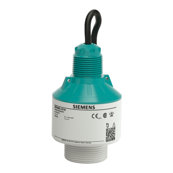
Page 15: Principle Of Operation
Description 3.2 Principle of operation Constituent parts Radar antenna Process fitting Electronics housing Mounting thread Connection cable Figure 3.1 Components of SITRANS LR110 Nameplate The nameplate contains the most important data for identification and use of the transmitter. Transmitter type Serial number Technical data Field for approvals QR code for device documentation... -
Page 16: Adjustment
The frequency change is proportional to the distance and is converted into the level. Adjustment Wireless adjustment Devices with integrated Bluetooth module can be adjusted wirelessly via Siemens mobile IQ app: • Smartphone/tablet (iOS or Android operating system) Transmitter Smart device Figure 3.3... -
Page 17: Accessories
Description 3.5 Accessories Transport Transport must be carried out in due consideration of the notes on the transport packaging. Nonobservance of these instructions can cause damage to the device. Transport inspection The delivery must be checked for completeness and possible transit damage immediately at receipt. -
Page 18: Installing/Mounting
Installing/mounting General instructions Ambient conditions The transmitter is suitable for standard and extended ambient conditions acc. to DIN/ EN/IEC/ANSI/ISA/UL/CSA 61010-1. It can be used indoors as well as outdoors. Process conditions Note For safety reasons, the transmitter must only be operated within the permissible process conditions. -
Page 19: Mounting Instructions
Installing/mounting 4.3 Mounting instructions Figure 4.1 Mounting via a mounting bracket Mounting instructions Installation position When mounting the device, keep a distance of at least 200 mm (7.874 in) from the vessel wall. If the device is installed in the center of dished or round vessel tops, multiple echoes can arise. - Page 20 Installing/mounting 4.3 Mounting instructions Reference point Figure 4.3 Reference point Inflowing medium Do not mount the transmitters in or above the filling stream. Make sure that you detect the medium surface, not the inflowing product. Figure 4.4 Mounting of the radar transmitter with inflowing medium Nozzle For nozzle mounting, the nozzle should be as short as possible and its end rounded.
- Page 21 Installing/mounting 4.3 Mounting instructions Figure 4.6 Nozzle mounting with deviating nozzle dimensions Nozzle diameter d Nozzle length h 40 mm 1½" ≤ 150 mm ≤ 5.9 in 50 mm 2" ≤ 200 mm ≤ 7.9 in 80 mm 3" ≤ 300 mm ≤ 11.8 in 100 mm 4" ≤ 400 mm ≤ 15.8 in 150 mm 6" ≤ 600 mm ≤ 23.6 in Orientation In liquids, direct the device as perpendicular as possible to the medium surface to achieve optimum measurement results.
-
Page 22: Measurement Setup - Flow
Installing/mounting 4.4 Measurement setup - Flow Figure 4.8 Agitators Foam generation Through the action of filling, stirring and other processes in the vessel, foams which considerably damp the emitted signals may form on the medium surface. If foams lead to measurement errors, you should use transmitters with guided radar. Measurement setup - Flow In general, the following must be observed while mounting the device: •... - Page 23 Installing/mounting 4.4 Measurement setup - Flow Rectangular overfall Overfall orifice (side view) Upstream water Tailwater Overfall orifice (view from tailwater) Figure 4.9 Flow measurement with rectangular flume: h = max. filling of the rectangular max. flume Khafagi-Venturi flume Position transmitter Venturi flume Figure 4.10 Flow measurement with Khafagi-Venturi flume: h = max.
-
Page 24: Connecting
Connecting Preparing the connection Safety instructions Always keep in mind the following safety instructions: • Carry out electrical connection by trained, qualified personnel authorised by the plant operator WARNING Only connect or disconnect in de-energized state. Voltage supply The data for power supply are specified in chapter " Technical data". Note Power the transmitter via an energy-limited circuit (power max. -
Page 25: Wiring Plan
Connecting 5.2 Wiring plan Wiring plan Wire assignment, connection cable Figure 5.1 Wire assignment in permanently connected connection cable Wire colour Function Polarity Brown Voltage supply Plus (+) Blue Voltage supply Minus (-) Black Modbus signal D+ Plus (+) White Modbus signal D- Minus (-) Shielding SITRANS LR110... -
Page 26: Access Protection
Access protection Bluetooth radio interface Devices with a Bluetooth radio interface are protected against unwanted access from outside. This means that only authorized persons can receive measured and status values and change device settings via this interface. Bluetooth PIN A Bluetooth PIN is required to establish Bluetooth communication via the adjustment tool (smartphone/tablet/notebook). - Page 27 Access protection 6.2 Protection of the parameterization Device Access PUK The Device Access PUK allows unlocking the device in case the user PIN is no longer known. It can't be changed. The Device Access PUK can also be found on the supplied information sheet "...
-
Page 28: Setup With Smart Device (Bluetooth)
Setup with smart device (Bluetooth) Connecting Connecting Start the adjustment app. The smart device searches automatically for Bluetooth- capable transmitters in the area. The devices found are listed. Select the requested transmitter in the device list. Authenticate When establishing the connection for the first time, the operating tool and the transmitter must authenticate each other. - Page 29 Setup with smart device (Bluetooth) 7.1 Connecting SITRANS LR110 Operating Instructions, 12/2020, A5E49829013...
-
Page 30: Operating
Operating To configure the device: Download and install the SITRANS mobile IQ app from the App store to your mobile device. Launch the app. Devices in range will appear. Click on the device you wish to connect to. On first connection, a PIN code shipped with the device needs to be entered (see Device Bluetooth and SITRANS LR110 Operating Instructions, 12/2020, A5E49829013... - Page 31 Operating Parameter Access Codes sheet). Following successful PIN entry, the device cockpit will be shown. SITRANS LR110 Operating Instructions, 12/2020, A5E49829013...
- Page 32 Operating Use the Setup/Quick Commissioning to configure the transmitter for your application type. SITRANS LR110 Operating Instructions, 12/2020, A5E49829013...
- Page 33 Operating Many diagnostic tools are supported, including the echo profile viewer: SITRANS LR110 Operating Instructions, 12/2020, A5E49829013...
-
Page 34: Diagnostics And Troubleshooting
Diagnostics and troubleshooting Maintenance Maintenance If the device is used properly, no special maintenance is required in normal operation. Precaution measures against buildup In some applications, buildup on the antenna system can influence the measuring result. Depending on the transmitter and application, take measures to avoid heavy soiling of the antenna system. -
Page 35: Status Messages According To Ne 107
Diagnostics and troubleshooting 9.3 Status messages according to NE 107 • Signal processing Fault rectification The first measures are: • Evaluation of fault messages • Checking the output signal • Treatment of measurement errors A smart device (smartphone/tablet) with the adjustment app or a PC/notebook with the PDM and the suitable EDD offer you further comprehensive diagnostic possibilities. - Page 36 Diagnostics and troubleshooting 9.3 Status messages according to NE 107 Code Cause Rectification Text message F105 The transmitter is still in the switch-on Wait for the end of the switch-on phase, the measured value could not phase Determine measured yet be determined value Duration up to 3 minutes depending on the measurement environment...
-
Page 37: Treatment Of Measurement Errors
Diagnostics and troubleshooting 9.4 Treatment of measurement errors Code Cause Rectification Text message Error in the delivery Load XML file with transmitter data status into the transmitter M501 Hardware error EEPROM Send transmitter for repair Error in the delivery status M507 Error during setup Carry out reset and repeat setup Error in the... - Page 38 Diagnostics and troubleshooting 9.4 Treatment of measurement errors Fault description Cause Rectification Measured value shows a Min./max. adjustment not correct Adapt min./max. adjustment too low or too high level Incorrect linearization curve Adapt linearization curve Measured value jumps Due to the process, the amplitude Carry out a auto false echo towards 100 % of the level echo sinks...
- Page 39 Diagnostics and troubleshooting 9.4 Treatment of measurement errors Fault description Cause Rectification Measured value jumps Varying condensation or Carry out a auto false echo sporadically to 100 % contamination on the antenna suppression or increase auto during filling false echo suppression with condensation/contamination in the close range by editing Measured value jumps to...
- Page 40 Diagnostics and troubleshooting 9.4 Treatment of measurement errors Fault description Cause Rectification Fault description Cause Rectification Measured value shows a Min./max. adjustment not correct Adapt min./max. adjustment too low or too high level Incorrect linearization curve Adapt linearization curve Measured value jumps Due to the process, the amplitude Carry out a auto false echo towards 100 %...
- Page 41 Diagnostics and troubleshooting 9.4 Treatment of measurement errors Fault description Cause Rectification Measured value jumps Changing condensation or Carry out a auto false echo sporadically to 100 % contamination on the antenna suppression or increase auto during filling false echo suppression with condensation/contamination in the close range by editing Fault description...
-
Page 42: Return Procedure
Required forms: • Delivery note • Return goods delivery note with the following information: https:// www.siemens.com/processtransmitteration/returngoodsnote • Product (item description) • Number of returned devices/replacements parts • Reason for returning the item(s) •... -
Page 43: Technical Support
[https://www.siemens.com/ processtransmitteration/certificates] or on an included DVD. How to proceed if a repair is necessary If it is necessary to repair the transmitter, please contact Siemens. You find the locations on " www.siemens.com/processautomation [https://www.siemens.com/ processautomation]. SITRANS LR110 Operating Instructions, 12/2020, A5E49829013... -
Page 44: Service And Maintenance
Devices can be returned to the supplier within the EC, or to a locally approved disposal service for eco-friendly recycling. Observe the specific regulations valid in your country. Further information about devices containing batteries can be found at: ( https:// support.industry.siemens.com/cs/document/109479891/) Note Special disposal required The device includes components that require special disposal. •... - Page 45 Service and maintenance 10.2 Disposal SITRANS LR110 Operating Instructions, 12/2020, A5E49829013...
-
Page 46: Certificates And Approvals
The Bluetooth radio module in the device has been tested and approved according to the current edition of the applicable country-specific norms or standards. The confirmations as well as regulations for use can be found in the document " Radio licenses" supplied or on www.siemens.com/level [https://www.siemens.com/ level]. 11.2 Approvals for Ex areas Approved versions for use in hazardous areas are available or in preparation for the device series. -
Page 47: Eu Conformity
Certificates and approvals 11.5 EU conformity You can find the respective certificates on www.siemens.com/level [https:// www.siemens.com/level]. 11.5 EU conformity The device fulfils the legal requirements of the applicable EU directives. By affixing the CE marking, we confirm the conformity of the transmitter with these directives. -
Page 48: Technical Data And Dimensions
Technical data Note for approved transmitters Device specifications: Siemens makes every effort to ensure the accuracy of these specifications, but reserves the right to change them at any time. Device-specific approvals: The device-specific approvals are always to be found on the nameplates on the device. - Page 49 Technical data and dimensions 12.1 Technical data Input variable Measured variable The measured variable is the distance between the antenna edge of the transmitter and the medium surface. The antenna edge is also the reference point for the measurement. Measuring range 0 … 15 m (0 … 49.21 ft) Min.
- Page 50 Technical data and dimensions 12.1 Technical data Characteristics and performance data Measuring frequency W-band (80 GHz technology) Measuring cycle time ≤ 250 ms Step response time ≤ 3 s Beam angle 8° With operating voltage U ≥ 24 V DC Time span after a sudden distance change from 1 m to 5 m until the output signal reaches 90 % of the final value for the first time (IEC 61298-2).
-
Page 51: Modbus - Overview
Technical data and dimensions 12.2 Modbus – Overview 12 DC 150 mW/330 mW 24 V DC 240 mW/420 mW Reverse voltage protection Integrated Overvoltage protection Dielectric strength against > 10 kV metallic mounting parts Overvoltage resistance (test > 1000 V impulse voltages 1.2/50 µs at 42 Ω) Additional overvoltage Due to the floating structure of the electronics and comprehensive arrester insulation measures generally not necessary. -
Page 52: Setup
Technical data and dimensions 12.4 Setup Register Register Name Data type Configurable Values Unit Default Number Value Baud Rate enum16 1200, 2400, 4800, – 9600 9600, 19200, 38400, 57600 Parity enum8 0 = None, 1 = Odd, 2 = – Even Stopbits enum8 1 = None, 2 = Two... - Page 53 Technical data and dimensions 12.5 Measured values Register Register Name Data Note Number type Access Gallons, 43=Cubic Meters, 44=Feet, 45=Meters, 46=Barrels, 47=Inches, 48=Centimeters, 49=Millimeters, 111=Cubic Yards, 112=Cubic Feet, 113=Cubic Inches float32 Primary Variable in Byte Order CDAB SV Unit enum16 Unit Code float32 Secondary Variable in Byte Order CDAB TV Unit...
-
Page 54: Additional Measurement Data
Technical data and dimensions 12.6 Additional measurement data Register Register Name Data Note Number type Access 2004 float32 Secondary Variable in Byte Order ABCD (Big Endian) 2006 float32 Third Variable in Byte Order ABCD (Big Endian) 2008 float32 Quarternary Variable in Byte Order ABCD (Big Endian) 2100 Status... -
Page 55: Diagnosis Data, Device Information
Technical data and dimensions 12.7 Diagnosis data, device information 12.7 Diagnosis data, device information Register Register Name Type Note Number 2300 Current uint32 According to NAMUR NE 107 recommendation diagnostic code 2307 Device status uint8 Current event category: 0 = ok, 1 = failure, 2 = check, 4 = maintenance, 8 = out of spec 2308 Device serial... - Page 56 Technical data and dimensions 12.8 Function codes Parameter Length Code/Data Start Address 2 Bytes Register Value 2 Bytes Data With this function code different diagnostic functions are triggered or diagnostic values read out. Parameter Length Code/Data Request: Function Code 1 Byte 0x08 Sub Function Code 2 Bytes...
-
Page 57: Configuration Of Typical Modbus Hosts
Technical data and dimensions 12.9 Configuration of typical Modbus hosts Parameter Length Code/Data Read Device ID Code 1 Byte 0x01 to 0x04 Object ID 1 Byte 0x00 to 0xFF Response: Function Code 1 Byte 0x2B MEI Type 1 Byte 0x0E Read Device ID Code 1 Byte 0x01 to 0x04 Confirmity Level... -
Page 58: Dimensions
Technical data and dimensions 12.10 Dimensions 12.10 Dimensions Figure 12.2 Dimensions SITRANS LR110 12.11 Licensing information for open source software Open source software components are also used in this device. A documentation of these components with the respective license type, the associated license texts, copyright notes and disclaimers can be found on our homepage. - Page 59 Technical data and dimensions 12.12 Trademark SITRANS LR110 Operating Instructions, 12/2020, A5E49829013...
- Page 60 Further Information Process Automation https://www.siemens.com/processautomation Industry Online Support (service and support) https://support.industry.siemens.com Industry Mall https://mall.industry.siemens.com Siemens AG Digital Industry Process Automation Postfach 48 48 90026 NÜRNBERG GERMANY...
Need help?
Do you have a question about the SITRANS L and is the answer not in the manual?
Questions and answers