Siemens SITRANS L Operating Instructions Manual
Radar transmitters
Hide thumbs
Also See for SITRANS L:
- Operating instructions manual (269 pages) ,
- Compact operating instructions (114 pages) ,
- Application examples (11 pages)

Related Manuals for Siemens SITRANS L


Summary of Contents for Siemens SITRANS L
- Page 1 Edition 10/2022 Operating Instructions SITRANS L Radar Transmitters SITRANS LR150 https://www.siemens.com/processautomation...
- Page 2 Preface Introduction Safety notes SITRANS L Description Radar Transmitters SITRANS LR150 Installing/mounting Connecting Operating Instructions Access protection Setup with the integrated Setup with smart device (Bluetooth) Setup with PC/notebook (HART modem) Operating Setup with SIMATIC PDM EDD Diagnostics and troubleshooting Service and maintenance...
- Page 3 Note the following: WARNING Siemens products may only be used for the applications described in the catalog and in the relevant technical documentation. If products and components from other manufacturers are used, these must be recommended or approved by Siemens. Proper transport, storage, installation, assembly, commissioning, operation and maintenance are required to ensure that the products operate safely and without any problems.
-
Page 4: Table Of Contents
Table of Contents Preface ............................vii Introduction ........................... 1 Function ........................ 1 Target group ......................1 Symbols used ......................1 Safety notes .......................... 3 Authorised personnel .................... 3 Appropriate use ....................3 Warning about incorrect use ................. 3 General safety instructions ..................3 Radar frequencies for worldwide use .............. - Page 5 Table of Contents Setup with the integrated HMI ................... 27 Adjustment system ....................27 Structure and views of the display ............... 28 Menu overview ....................31 Parameterization ....................36 Quick setup ......................36 7.5.1 Wizards for quick setup ..................36 7.5.2 Quick setup level, space, distance ...............
- Page 6 Table of Contents Diagnostics and troubleshooting ..................79 12.1 Maintenance ....................... 79 12.2 Rectify faults ....................... 79 12.3 Diagnosis, fault messages ................... 80 12.4 Status messages according to NE 107 ..............80 12.5 Treatment of measurement errors ............... 84 12.6 Return procedure ....................88 12.7 Technical support ....................
- Page 7 Table of Contents SITRANS LR150 Operating Instructions, 10/2022, 62711-76-01, A5E50352155...
-
Page 8: Preface
Preface Safety instructions for Ex areas: WARNING Take note of the Ex specific safety instructions for Ex applications. These instructions are attached as documents to each transmitter with Ex approval and are part of the operating instructions. Editing status: 2022-10-26 SITRANS LR150 Operating Instructions, 10/2022, 62711-76-01, A5E50352155... - Page 9 Preface viii SITRANS LR150 Operating Instructions, 10/2022, 62711-76-01, A5E50352155...
-
Page 10: Introduction
Introduction Function This instruction provides all the information you need for mounting, connection and setup as well as important instructions for maintenance, fault rectification, the exchange of parts and the safety of the user. Please read this information before putting the transmitter into operation and keep this manual accessible in the immediate vicinity of the device. - Page 11 Introduction 1.3 Symbols used Sequence of actions Numbers set in front indicate successive steps in a procedure. Disposal This symbol indicates special instructions for disposal. SITRANS LR150 Operating Instructions, 10/2022, 62711-76-01, A5E50352155...
-
Page 12: Safety Notes
Safety notes Authorised personnel All operations described in this documentation must be carried out only by trained, qualified personnel authorised by the plant operator. During work on and with the device, the required personal protective equipment must always be worn. Appropriate use SITRANS LR150 is a transmitter for continuous level measurement. -
Page 13: Radar Frequencies For Worldwide Use
Installations in Canada shall comply with the relevant requirements of the Canadian Electrical Code. Security information Siemens provides products and solutions with industrial security functions that support the secure operation of plants, systems, machines and networks. To protect plants, systems, machines and networks against cyber threats, it is necessary to implement (and continuously maintain) a holistic, state-of-the-art industrial security concept. - Page 14 Use of product versions that are no longer supported, and failure to apply the latest updates may increase customer’s exposure to cyber threats. To stay informed about product updates, subscribe to the Siemens Industrial Security RSS Feed under: https://www.siemens.com/industrialsecurity...
- Page 15 Safety notes 2.7 Security information SITRANS LR150 Operating Instructions, 10/2022, 62711-76-01, A5E50352155...
-
Page 16: Description
Description Configuration Scope of delivery The scope of delivery encompasses: • SITRANS LR150 radar transmitter • Information sheet " Documents and software" with: • Transmitter serial number • QR code with link for direct scanning • Information sheet " Device Bluetooth and Parameter Access Codes" with: •... -
Page 17: Principle Of Operation
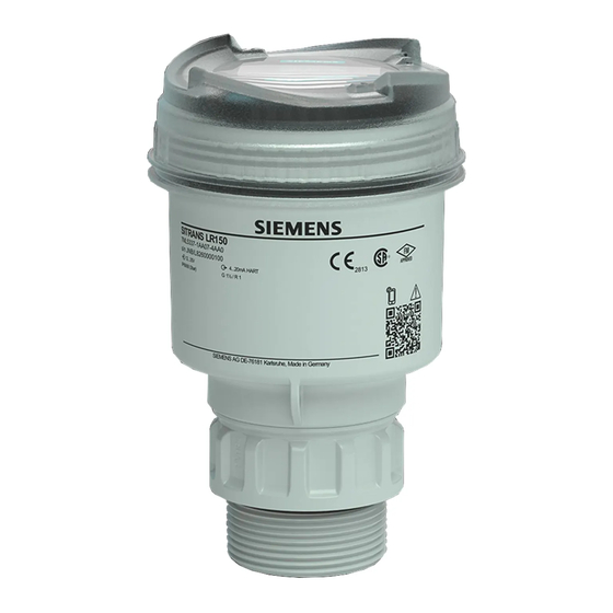
Description 3.2 Principle of operation Constituent parts Radar antenna Process fitting Process seal (G type threaded connections only) Electronics housing Display and adjustment unit Ventilation/pressure compensation Figure 3.1 Components of SITRANS LR150 (Example process fitting G1½) Nameplate The nameplate contains the most important data for identification and use of the transmitter. -
Page 18: Adjustment
Local adjustment On-site adjustment of the device is carried out via the optionally integrated HMI. Wireless adjustment Devices with integrated Bluetooth module can be adjusted wirelessly via Siemens mobile IQ app. Transmitter Smart device Figure 3.3 Wireless connection to standard operating devices with integrated Bluetooth LE Adjustment via the signal cable Devices with signal output 4 … 20 mA/HART can also be operated via a signal cable. -
Page 19: Packaging, Transport And Storage
Description 3.4 Packaging, transport and storage Transmitter HART resistance 250 Ω (optional depending on evaluation) Control system Handheld Figure 3.4 Connecting the PC to the signal cable Packaging, transport and storage Packaging Your transmitter was protected by packaging during transport. Its capacity to handle normal loads during transport is assured by a test based on ISO 4180. - Page 20 Description 3.4 Packaging, transport and storage • Not in the open • Dry and dust free • Not exposed to corrosive media • Protected against solar radiation • Avoiding mechanical shock and vibration Storage and transport temperature Storage and transport temperature see chapter " Supplement - Technical data - •...
- Page 21 Description 3.4 Packaging, transport and storage SITRANS LR150 Operating Instructions, 10/2022, 62711-76-01, A5E50352155...
-
Page 22: Installing/Mounting
Installing/mounting General instructions Ambient conditions The transmitter is suitable for standard and extended ambient conditions acc. to DIN/ EN/IEC/ANSI/ISA/UL/CSA 61010-1. It can be used indoors as well as outdoors. Process conditions Note For safety reasons, the transmitter must only be operated within the permissible process conditions. - Page 23 Installing/mounting 4.2 Mounting instructions The polarization direction is marked on the housing, see following drawing: Marking of the polarisation Figure 4.1 Position of the polarisation Note When the housing is rotated, the direction of polarization changes and hence the influence of the false echo on the measured value. Please keep this in mind when mounting or making changes later.
- Page 24 Installing/mounting 4.2 Mounting instructions Figure 4.3 Mounting of the radar transmitter on round vessel tops In vessels with conical bottom it can be advantageous to mount the device in the centre of the vessel, as measurement is then possible down to the bottom. Figure 4.4 Mounting of the radar transmitter on vessels with conical bottom Inflowing medium...
- Page 25 Installing/mounting 4.2 Mounting instructions Figure 4.6 Thread mounting If the reflective properties of the medium are good, you can mount SITRANS LR150 on nozzles longer than the antenna. The nozzle end should be smooth and burr-free, if possible also rounded. You will find recommended values for nozzle heights in the following illustration or the table.
-
Page 26: Measurement Setup - Flow
Installing/mounting 4.3 Measurement setup - Flow Agitators If there are agitators in the vessel, a auto false echo suppression should be carried out with the agitators in motion. This ensures that the interfering reflections from the agitators are saved with the blades in different positions. Figure 4.9 Agitators Foam generation... - Page 27 Installing/mounting 4.3 Measurement setup - Flow Flume Predefined curves: A flow measurement with these standard curves is very easy to set up, as no dimensional information of the flume is required. 1.86 • Palmer-Bowlus flume (Q = k x h • Venturi, trapezoidal weir, rectangular flume (Q = k x h •...
- Page 28 Installing/mounting 4.3 Measurement setup - Flow Rectangular overfall Overfall orifice (side view) Upstream water Tailwater Overfall orifice (view from tailwater) Figure 4.10 Flow measurement with rectangular flume: h = max. filling of the rectangular max. flume Khafagi-Venturi flume Position transmitter Venturi flume Figure 4.11 Flow measurement with Khafagi-Venturi flume: h = max.
- Page 29 Installing/mounting 4.3 Measurement setup - Flow SITRANS LR150 Operating Instructions, 10/2022, 62711-76-01, A5E50352155...
-
Page 30: Connecting
Connecting Preparing the connection Safety instructions Always keep in mind the following safety instructions: • Carry out electrical connection by trained, qualified personnel authorised by the plant operator WARNING Only connect or disconnect in de-energized state. Voltage supply The data for power supply are specified in chapter " Technical data". Note Power the transmitter via an energy-limited circuit (power max. -
Page 31: Connecting
Connecting 5.2 Connecting Note Shielded cable generally necessary in HART multidrop mode. Note If the temperatures are too high, the cable insulation can be damaged. Hence keep apart from the ambient temperature also the self-heating of the transmitter for the temperature resistance of the cable in the connection compartment in mind (With an ambient temperature ≥ 50 °C (122 °F) the connection cable should be suitable for a temperature which is at least 20 °C (36 °F) higher.). -
Page 32: Wiring Plan
Connecting 5.3 Wiring plan Note Fixed conductors and flexible conductors with ferrules can be inserted directly into the terminal openings. In the case of flexible conductors for opening the terminals, use a screwdriver (3 mm blade width) to push the actuator lever away from the terminal opening. -
Page 33: Connecting Hmi To Electronic Module
Connecting 5.4 Connecting HMI to electronic module Plug connector for HMI Figure 5.2 Connection compartment SITRANS LR150 Connecting HMI to electronic module Switch-on phase After connection to the power supply, the device carries out a self-test: • Internal check of the electronics •... -
Page 34: Access Protection
Access protection Bluetooth radio interface Devices with a Bluetooth radio interface are protected against unwanted access from outside. This means that only authorized persons can receive measured and status values and change device settings via this interface. Bluetooth PIN A Bluetooth PIN is required to establish Bluetooth communication via the adjustment tool (smartphone/tablet/notebook). - Page 35 Access protection 6.2 Protection of the parameterization Device Access PUK The Device Access PUK allows unlocking the device in case the user PIN is no longer known. It can't be changed. The Device Access PUK can also be found on the supplied information sheet "...
-
Page 36: Setup With The Integrated Hmi
Setup with the integrated HMI Adjustment system Function The transmitter is operated via the four keys of the integrated display and adjustment unit. The respective menu items are shown on the HMI. You can find the function of the individual keys in the following overview. Display and adjustment elements Adjustment keys Figure 7.1... -
Page 37: Structure And Views Of The Display
Setup with the integrated HMI 7.2 Structure and views of the display Function Measured value view: Select the desired measured value Parameter view: Select parameter Editing view: Change parameter value downwards Measured value view: Navigate to main menu or parameter view Parameter view: Navigate to edit view Editing view: confirm selected parameter value Time functions... - Page 38 Setup with the integrated HMI 7.2 Structure and views of the display Display symbols INFO field Symbol Meaning Device is write protected via parameter " User PIN". Loop test in operation EDIT When the symbol flashes, you can edit the parameter. INFO Diagnostic message.
- Page 39 Setup with the integrated HMI 7.2 Structure and views of the display Setting Description STEMP Electronics temperature If the mode of operation is set accordingly If the mode of operation is set accordingly Note If the measured value cannot be shown in the display, " 99999" appears flashing. In this case the selected unit or scaling must be adapted.
-
Page 40: Menu Overview
Setup with the integrated HMI 7.3 Menu overview EDIT" symbol (flashing) Figure 7.5 Editing view Ten minutes after the last key is pressed, an automatic return to the measured value view is triggered. Parameter changes that have not yet been confirmed are lost. Menu overview Menu item Parameter... - Page 41 Setup with the integrated HMI 7.3 Menu overview Menu item Parameter Setting Default OPEN Level of open liquid DEMO Demonstration MATERIAL TYPE SOLID SILO Silo SILO Buffer, surge bin OPEN Heap, pile UNITS, LOWER CAL PT, See OPERATION = LEVEL UPPER CAL PT, CONFIRM COMMISSION OPERATION = VOLUME MATERIAL TYPE LIQUID...
- Page 42 Setup with the integrated HMI 7.3 Menu overview Menu item Parameter Setting Default VFLOW UNITS = Level l/s, l/min, l/h, MI/d, m /s, m /min, m /h, m Scaling: ScalingUnit d, lb/s, lb/min, lb/h, gal/s, gal/min, gal/h, gal/d, Mgal/d, ft /s, ft /min, ft /h, ft /d, bbl/...
- Page 43 Setup with the integrated HMI 7.3 Menu overview Menu item Parameter Setting Default FAULT CUR = ≤ 3.6 mA, ≥ 21 mA ≤ 3.6 mA Main Current Output_Configuration1: Current Limits FAIL SAFE LOE = Echo HOLD = off HOLD Loss Detection: Mode FAULT = Failure LOE TIMER Echo Loss Detection: Echo Loss Time 15 s VOLUME...
- Page 44 Setup with the integrated HMI 7.3 Menu overview Menu item Parameter Setting Default AFES OFF False Signal Calculation: Manual Curve not active AFES False Signal Manual Action: 0 mm RANGE Distance PEAK VALUES MIN DISTANCE Min Level Distance MAX DISTANCE Max Level Distance TR TEMP MIN Min Electronic Temperature TR TEMP MAX...
-
Page 45: Parameterization
Setup with the integrated HMI 7.4 Parameterization Parameterization Starting From the measured value view, you can access the parameter view with the " → key, and by pressing " → again you can access the first menu level. Select Navigate to the desired parameter. Press "... - Page 46 Setup with the integrated HMI 7.5.1 Wizards for quick setup Procedure The first steps of the wizard are the same for all application types. The subsequent parameters of the wizard differ depending on the selected application. Three separate lists follow for documentation purposes. These lists contain the parameters of the wizard that are available for setting up each type of application.
-
Page 47: 7.5.2 Quick Setup Level, Space, Distance
Setup with the integrated HMI 7.5.2 Quick setup level, space, distance 7.5.2 Quick setup level, space, distance Mode OPERATION: LEVEL, SPACE, DIST Sets the mode of operation that determines the output and display: Setting Description LEVEL Level SPACE Space DIST Distance Volume VFLOW Volume flow... - Page 48 Setup with the integrated HMI 7.5.2 Quick setup level, space, distance Material type Used to optimize the device function depending on the type of material and vessel or application: Setting Selection Selection Vessel MATERIAL TYPE LIQUID STRGE Process vessel with agitation PRCSS Wet well WTWLL...
-
Page 49: 7.5.3 Quick Setup Volume
Setup with the integrated HMI 7.5.3 Quick setup volume Setting No: The wizard is closed and settings are not applied. They must be entered again when the wizard is run again. 7.5.3 Quick setup volume Mode OPERATION: Sets the mode of operation that determines the output and display: Setting Description LEVEL... - Page 50 Setup with the integrated HMI 7.5.3 Quick setup volume Setting Description Reference point Volume Volume of the material in Lower calibration point volume unit (related to the level) Material type Used to optimize the device function depending on the type of material and vessel or application: Setting Selection...
- Page 51 Setup with the integrated HMI 7.5.3 Quick setup volume Vessel dimension A VESSEL DIM A: Adjusts the height of the vessel bottom in the case of a conical or flat inclined bottom. Lower calibration point LOWER CAL PT: Sets the distance from the transmitter reference point to the lower calibration point: usually corresponds to the zero point of the process.
-
Page 52: Quick Setup Volume Flow
Setup with the integrated HMI 7.5.4 Quick setup volume flow 7.5.4 Quick setup volume flow Mode OPERATION: Sets the mode of operation that determines the output and display: Setting Description Level LEVEL Space SPACE Distance DIST Volume Volume flow VFLOW Transmitter reference point Upper calibration point Lower calibration point Far range... - Page 53 Setup with the integrated HMI 7.5.4 Quick setup volume flow Material type Used to optimize the device function depending on the type of material or application: Setting Selection Selection Selection MATERIAL TYPE LIQUID OPEN Open basin FLOW Open flume DEMO Demonstration Unit UNITS: Sets the measuring unit used (default setting in brackets):...
- Page 54 Setup with the integrated HMI 7.5.4 Quick setup volume flow Volume flow unit FLOW UNITS: Sets the measuring units for the volume. • Litres per second (l/s) • Litres per minute (l/m) • Litres per hour (l/h) • Mega litres per day (Ml/d) •...
-
Page 55: 7.5.5 Quick Setup Auto False Echo Suppression
Setup with the integrated HMI 7.5.5 Quick setup auto false echo suppression Final scaling value UPPER SCALNG: Sets the process value that corresponds to a loop current of 20 mA. Confirm CONFIRM: Accepts the settings as the last step in the wizard. Setting Yes: The wizard is closed and settings are applied. -
Page 56: Application Examples
Setup with the integrated HMI 7.6 Application examples As soon as the wizard is successfully completed, parameter " Auto false echo suppression" is set to " Activated" and the determined TVT curve is used. Confirm CONFIRM: Accepts the settings as the last step in the wizard. Setting Yes: The wizard is closed and settings are applied. -
Page 57: 7.6.2 Application Example Volume Flow
Setup with the integrated HMI 7.6.2 Application example volume flow Quick commissioning Setting/value Description parameter Unit Measuring unit of the transmitter Lower calibration point 9.0 m Zero point of the process Upper calibration point 1.0 m Full point of the process 7.6.2 Application example volume flow In this example, a 12 inch (0.305 m) venturi flume is installed in an open channel. -
Page 58: Settings
Setup with the integrated HMI 7.7 Settings Quick Setting/value Description commissioning parameter Material type Liquid Measuring Liquid RWRC Venturi flume structure Lower calibration Distance to the empty point point or bottom of the measuring channel. Adjusts the material level at 4 mA. Upper calibration Distance to maximum level. -
Page 59: Transmitter
Setup with the integrated HMI 7.7.2 Transmitter Linearization type Sets the type of linearization to calculate the volume or volume flow. 7.7.2 Transmitter Units Sets the measuring unit used. Setting Selection Selection Description Transmitter UNITS Millimetre Meter Inch Feet 7.7.3 Adjustment Lower calibration point LOWER CAL POINT: Sets the distance from the transmitter reference point to the lower calibration point. -
Page 60: Current Output
Setup with the integrated HMI 7.7.4 Current output 7.7.4 Current output Loop current mode Sets the operation of the current output as loop current 4 … 20 mA, or as fixed current value 4 mA for the HART multidrop mode. Setting Selection Selection Description CURRENT OUT LOOP CUR MDE 4 … 20 mA 4 mA fix... -
Page 61: 7.7.5 Volume
Setup with the integrated HMI 7.7.5 Volume Setting Selection Selection Description 4 … 20 mA Fault current Sets the current value that is output in case of an error. Setting Selection Selection Description CURRENT OUT FAULT CUR ≤ 3.6 mA ≥ 21 mA Safety function with echo loss Defines the behavior of the safety function in case of echo loss and expiration of the LOE timer. -
Page 62: 7.7.6 Volume Flow
Setup with the integrated HMI 7.7.6 Volume flow Setting Selection Selection Description Other required parameters VOLUME VESSEL SHAPE LINR Linear vessel Upper scaling point CONIC Conical vessel bottom Upper scaling point, vessel dimension A FLAT SLOPE Container with flat sloping bottom Upper scaling point, vessel dimension A CYLIN... - Page 63 Setup with the integrated HMI 7.7.6 Volume flow Note This menu is only visible on the device if it is configured. Lower calibration point LOWER CAL POINT: Sets the distance from the transmitter reference point to the lower calibration point. Upper calibration point UPPER CAL POINT: Sets the distance from the transmitter reference point to the upper calibration point.
-
Page 64: Custom
Setup with the integrated HMI 7.7.7 Custom If the value for one of these parameters is set outside the wizard, the other value is not automatically adjusted. 7.7.7 Custom This menu is only visible on the device if the vessel shape " Custom specific" is configured for the volume flow mode or if the measuring structure "... -
Page 65: Display
Setup with the integrated HMI 7.7.8 Display 7.7.8 Display Start view Sets the process value that appears first on the display after switching on. Setting Description LOCL DISPLAY Level LEVEL Space SPACE Distance DIST Volume Volume flow VFLOW Loop current LOOPC Percentage value Electronics temperature STEMP... - Page 66 Setup with the integrated HMI 7.8.1 Signal Signal quality Echo quality: Displays the echo quality. The higher the value, the higher the echo quality. Echo signal strength: Displays the strength of the valid echo in dB. Noise average value: Displays the average value of the noise in dB. Setting Selection Selection...
-
Page 67: Peak Values
Setup with the integrated HMI 7.8.2 Peak values Make sure that the material level is below all known installations when using the " Auto false echo suppression wizard" to determine the TVT. Ideally the vessel should be empty or almost empty. Note the distance to the material level when determining the echo profile and set the value in parameter "... -
Page 68: Circuit Test
Setup with the integrated HMI 7.8.3 Circuit test Max. measured distance MAX DISTANCE: Displays the value of the maximum measured distance. The value may reset if the unit is changed. Minimum electronics temperature TR TEMP MIN: Displays the value of the minimum transmitter temperature. Maximum electronics temperature TR TEMP MAX: Displays the value of the maximum transmitter temperature. -
Page 69: Resets
Setup with the integrated HMI 7.8.4 Resets 7.8.4 Resets Restart transmitter Is used to restart the device without switching off the supply voltage. Note The simulation is interrupted. Saved configurations are not reset Setting Selection Selection Description RESET DEVICE RSTRT CANCL Cancel Restart transmitter Reset... -
Page 70: Frequency
Setup with the integrated HMI 7.8.5 Frequency Setting Selection Selection Description RESET RESET PEAK Cancel DIST Distance STEMP Electronics temperature 7.8.5 Frequency Frequency Country specific settings for the radar signals are determined via the menu item frequency. • Mode 1: EU, Albania, Andorra, Azerbaijan, Australia, Belarus, Bosnia and Herzegovina, Canada, Liechtenstein, Morocco, Moldavia, Monaco, Montenegro, New Zealand, Northern Macedonia, Norway, San Marino, Saudi Arabia, Serbia, Switzerland, Turkey, Ukraine, United Kingdom, USA... -
Page 71: Communication
Setup with the integrated HMI 7.9 Communication Communication 7.9.1 HART address Function POLLING ADR: Sets the device address in a HART network. For point-to-point configurations the standard address is zero (0). For multidrop configurations, use a non-zero HART address, i.e. 1 to 63. 7.10 Safety 7.10.1... - Page 72 Setup with the integrated HMI 7.10.2 Bluetooth PIN is changed by the user and is no longer available, access is only possible via the emergency Bluetooth unlock code on the information sheet also supplied. SITRANS LR150 Operating Instructions, 10/2022, 62711-76-01, A5E50352155...
- Page 73 Setup with the integrated HMI 7.10.2 Bluetooth PIN SITRANS LR150 Operating Instructions, 10/2022, 62711-76-01, A5E50352155...
-
Page 74: Setup With Smart Device (Bluetooth)
Setup with smart device (Bluetooth) Connecting Connecting Start the adjustment app. The smart device searches automatically for Bluetooth- capable transmitters in the area. The devices found are listed. Select the requested transmitter in the device list. Authenticate When establishing the connection for the first time, the operating tool and the transmitter must authenticate each other. - Page 75 Setup with smart device (Bluetooth) 8.1 Connecting SITRANS LR150 Operating Instructions, 10/2022, 62711-76-01, A5E50352155...
-
Page 76: Setup With Pc/Notebook (Hart Modem)
Setup with PC/notebook (HART modem) Saving the parameterization data We recommend documenting or saving the parameterization data via SIMATIC PDM. That way the data are available for multiple use or service purposes. SITRANS LR150 Operating Instructions, 10/2022, 62711-76-01, A5E50352155... - Page 77 Setup with PC/notebook (HART modem) 9.1 Saving the parameterization data SITRANS LR150 Operating Instructions, 10/2022, 62711-76-01, A5E50352155...
-
Page 78: Operating
Operating To configure the device: Download and install the SITRANS mobile IQ app from the App store to your mobile device. Launch the app. Devices in range will appear. Click on the device you wish to connect to. On first connection, a PIN code shipped with the device needs to be entered (see Device Bluetooth and SITRANS LR150 Operating Instructions, 10/2022, 62711-76-01, A5E50352155... - Page 79 Operating Parameter Access Codes sheet). Following successful PIN entry, the device cockpit will be shown. SITRANS LR150 Operating Instructions, 10/2022, 62711-76-01, A5E50352155...
- Page 80 Operating Use the Setup/Quick Commissioning to configure the transmitter for your application type. SITRANS LR150 Operating Instructions, 10/2022, 62711-76-01, A5E50352155...
- Page 81 Operating SITRANS LR150 Operating Instructions, 10/2022, 62711-76-01, A5E50352155...
- Page 82 Operating • Mode 1: EU, Albania, Andorra, Azerbaijan, Australia, Belarus, Bosnia and Herzegovina, Canada, Liechtenstein, Morocco, Moldavia, Monaco, Montenegro, New Zealand, Northern Macedonia, Norway, San Marino, Saudi Arabia, Serbia, Switzerland, Turkey, Ukraine, United Kingdom, USA • Mode 2: Brazil, Japan, South Korea, Taiwan, Thailand •...
- Page 83 Operating SITRANS LR150 Operating Instructions, 10/2022, 62711-76-01, A5E50352155...
-
Page 84: Setup With Simatic Pdm Edd
SIMATIC PDM is a software package used to commission and maintain process devices: https://support.industry.siemens.com/cs/ww/en/view/109755005 Check the support page of our website to make sure you have the latest version of SIMATIC PDM, the most recent Service Pack (SP) and the most recent hot fix (HF). Go Software downloads: http://www.siemens.com/processinstrumentation/downloads... - Page 85 Setup with SIMATIC PDM EDD 11.1 Setup with SIMATIC PDM EDD Open the menu " Device > Download to device…". When complete, select " File > Save" to save the settings offline. The status fields are cleared. Figure 11.1 PDM structure view EDD offline, start Figure 11.2 PDM structure view EDD offline, continuation Procedure Select "...
- Page 86 Setup with SIMATIC PDM EDD 11.1 Setup with SIMATIC PDM EDD Figure 11.3 PDM quick setup wizard Select " Device > Echo profile utilities" to confirm the signal quality. Select the curves to be loaded into the echo profile view, then select " Load selected curves". Curves and other diagnostic information will be loaded after approximately 45 seconds.
- Page 87 SIMATIC PDM supports many other useful features, extensive diagnostic support and asset management. Details are found in the SIMATIC PDM manual here https:// support.industry.siemens.com/cs/ww/en/view/109755005 SITRANS LR150 Operating Instructions, 10/2022, 62711-76-01, A5E50352155...
-
Page 88: Diagnostics And Troubleshooting
Diagnostics and troubleshooting 12.1 Maintenance Maintenance If the device is used properly, no special maintenance is required in normal operation. Precaution measures against buildup In some applications, buildup on the antenna system can influence the measuring result. Depending on the transmitter and application, take measures to avoid heavy soiling of the antenna system. -
Page 89: Diagnosis, Fault Messages
Diagnostics and troubleshooting 12.3 Diagnosis, fault messages • Signal processing Fault rectification The first measures are: • Evaluation of fault messages • Checking the output signal • Treatment of measurement errors A smart device (smartphone/tablet) with the adjustment app or a PC/notebook with the PDM and the suitable EDD offer you further comprehensive diagnostic possibilities. - Page 90 Diagnostics and troubleshooting 12.4 Status messages according to NE 107 more detailed error messages available under the menu item " Diagnostics" via the respective adjustment module. Status messages The status messages are divided into the following categories: • Failure • Function check •...
- Page 91 Diagnostics and troubleshooting 12.4 Status messages according to NE 107 Failure Code Cause Rectification DevSpec Text message State in CMD 48 F013 No measured value in the Check or correct installation Byte 5, Bit 0 of switch-on phase or during and/or parameter settings Byte 0 … 5 no measured operation value available...
- Page 92 Diagnostics and troubleshooting 12.4 Status messages according to NE 107 Code Cause Rectification DevSpec Text message State in CMD 48 Wait for the automatic end "Standardized after 60 mins. Status 0" Out of specification Code Cause Rectification DevSpec Text message State in CMD 48 S600 Temperature of the electronics Check ambient temperature...
-
Page 93: Treatment Of Measurement Errors
Diagnostics and troubleshooting 12.5 Treatment of measurement errors Code Cause Rectification DevSpec Text message State in CMD 48 with the main controller M511 A software unit requires a Carry out software update Bit 11 of software update Byte 14 … 24 Inconsistent software configuration 12.5 Treatment of measurement errors The tables below give typical examples of application-related measurement errors. - Page 94 Diagnostics and troubleshooting 12.5 Treatment of measurement errors Fault description Cause Rectification false echo suppression no longer auto false echo suppression, e.g. matches actual conditions with condensation. Fault description Cause Rectification Measured value remains False signals in the close range too Eliminate false signals in the close unchanged during filling big or level echo too small...
- Page 95 Diagnostics and troubleshooting 12.5 Treatment of measurement errors Fault description Cause Rectification Measured value jumps to Level echo is no longer detected Check measuring point: Antenna ≥ 100 % or 0 m distance in the close range due to foam should protrude out of the threaded generation or false signals in the mounting nozzle, possible false close range.
- Page 96 Diagnostics and troubleshooting 12.5 Treatment of measurement errors Fault description Cause Rectification Measured value jumps Due to the process, the amplitude Carry out a auto false echo towards 100 % of the product echo decreases suppression A auto false echo suppression was not carried out Amplitude or position of a Determine the reason for the...
-
Page 97: Return Procedure
Diagnostics and troubleshooting 12.6 Return procedure Fault description Cause Rectification Measured value remains False signal greater than level echo Eliminate false signals in the close unchanged in the close or level echo too small range. Check: Antenna must range during emptying protrude out of the nozzle Remove contamination on the antenna... -
Page 98: Technical Support
[https://www.siemens.com/automation/support-request]. More information about our technical support is available at www.siemens.com/ automation/csi/service [https://www.siemens.com/automation/csi/service] Internet service and support In addition to our documentation, Siemens provides a comprehensive support solution at www.siemens.com/automation/service&support [https:// www.siemens.com/automation/service&support] Contact person If you have additional questions about the device, please contact your Siemens personal contact at www.automation.siemens.com/partner [https://... -
Page 99: How To Proceed If A Repair Is Necessary
[https://www.siemens.com/ processinstrumentation/certificates] or on an included DVD. 12.8 How to proceed if a repair is necessary If it is necessary to repair the transmitter, please contact Siemens. You find the locations on " www.siemens.com/processautomation [https://www.siemens.com/ processautomation]. SITRANS LR150 Operating Instructions, 10/2022, 62711-76-01, A5E50352155... -
Page 100: Service And Maintenance
If you have no way to dispose of the old transmitter properly, please contact us concerning return and disposal. Further information about devices containing batteries can be found at: ( https:// support.industry.siemens.com/cs/document/109479891/) Note Special disposal required The device includes components that require special disposal. - Page 101 Service and maintenance 13.2 Disposal SITRANS LR150 Operating Instructions, 10/2022, 62711-76-01, A5E50352155...
-
Page 102: Certificates And Approvals
The Bluetooth radio module in the device has been tested and approved according to the current edition of the applicable country-specific norms or standards. The confirmations as well as regulations for use can be found in the document " Radio licenses" supplied or on www.siemens.com/level [https://www.siemens.com/ level]. 14.2 Approvals for Ex areas Approved versions for use in hazardous areas are available or in preparation for the device series. -
Page 103: Food And Pharmaceutical Certificates
Food and pharmaceutical certificates Versions for use in the food and pharmaceutical industries are available or in preparation. You can find the respective certificates on www.siemens.com/level [https:// www.siemens.com/level]. 14.6 Conformity The device complies with the legal requirements of the applicable country-specific directives or technical regulations. -
Page 104: Technical Data And Dimensions
Technical data Note for approved transmitters Device specifications: Siemens makes every effort to ensure the accuracy of these specifications, but reserves the right to change them at any time. Device-specific approvals: The device-specific approvals are always to be found on the nameplates on the device. - Page 105 Technical data and dimensions 15.1 Technical data • Mode 1, 2, 4 0 mm (0 in) • Mode 3 ≥ 250 mm (9.843 in) Depending on application and medium Depending on the operating conditions Switch-on phase Run-up time for U = 12 V DC, 18 V DC, 24 V DC < 15 s Starting current for run-up time ≤ 3.6 mA Power consumption Run-up time...
- Page 106 Technical data and dimensions 15.1 Technical data • SV (Secondary Value) Distance • TV (Third Value) Measurement reliability • QV (Fourth Value) Electronics temperature Fulfilled HART specification Further information on Manufacturer ID, Device See website of FieldComm Group ID, Device Revision Default values can be assigned individually.
- Page 107 Technical data and dimensions 15.1 Technical data Characteristics and performance data Measuring frequency W-band (80 GHz technology) Measuring cycle time ≤ 250 ms Step response time ≤ 3 s Beam angle 8° Min. dielectric constant of the medium With operating voltage U ≥ 24 V DC Time span after a sudden distance change from 1 m to 5 m until the output signal reaches 90 % of the final value for the first time (IEC 61298-2).
- Page 108 Technical data and dimensions 15.1 Technical data Max. emitted power +2.2 dBm Max. number of participants Effective range typ. 25 m (82 ft) Depending on the local conditions Indication Measured value and menu display • Optional HMI LCD display with backlight • Max. indicating range -99999 … 99999 Adjustment Optional HMI...
-
Page 109: Dimensions
Technical data and dimensions 15.2 Dimensions 15.2 Dimensions Ventilation/pressure compensation Housing lid Process fitting Figure 15.2 Dimensions SITRANS LR150 15.3 Licensing information for open source software Open source software components are also used in this device. A documentation of these components with the respective license type, the associated license texts, copyright notes and disclaimers can be found on our homepage. - Page 110 For more information Process Automation https://www.siemens.com/processautomation Industry Online Support (service and support) https://support.industry.siemens.com Industry Mall https://mall.industry.siemens.com Siemens AG Measurement Intelligence Process Automation 76181, Karlsruhe Germany © 2023 Siemens AG Subject to change A5E50352155...
Need help?
Do you have a question about the SITRANS L and is the answer not in the manual?
Questions and answers