
Related Manuals for ABB NGC8200


Summary of Contents for ABB NGC8200
- Page 1 — A B B MEA SU R E ME N T & A N A LYT I CS | 2 1 015 1 0 MNA H Gas Chromatograph User Manual NGC8200/PGC1000 Measurement made easy...
-
Page 2: Table Of Contents
— Contents Contents ...........................2 List of tables ........................6 Additional information .......................7 Compliance ........................7 Cyber security ......................... 7 Malware prevention ......................8 Waste Electrical and Electronic Equipment (WEEE)..............8 Safety ..........................8 Potential safety hazards ....................9 1. Product description ..................... 10 Overview ...................... - Page 3 Cathodic protection ................... 44 5.2.6 Wire the analyzer power connector .............. 44 6 Startup ........................45 Download PCCU32 from the ABB website ..............45 Install PCCU32 ...................... 47 Establish initial local communication ................. 48 6.3.1 Connect using USB port (standard) .............. 48 6.3.2...
- Page 4 6.5.7 Enable/Disable streams ................66 6.5.8 Run Analysis Process streams ..............67 6.5.9 Complete startup ..................68 Manual peak find ....................69 6.6.1 Troubleshoot peak find ................73 7 Calibrate the analyzer ....................75 Verify calibration data using peak find ............... 78 8 Configure for network connection ................
- Page 5 10.13 Replace calibration or carrier gas cylinder(s) ............109 10.14 Replace the digital controller assembly ..............109 10.15 Replace the digital controller complete assembly ............110 10.16 Replace the analytical module................111 10.17 Replace the GC Module ..................113 10.18 Replace the termination panel ................114 10.19 Replace the feed-through assembly ................
-
Page 6: List Of Tables
11.2.25 Stream Un-normalized Total ..............132 11.3 Alarm troubleshooting tests................... 132 11.3.1 Column vent pressure test ............... 132 11.3.2 Sample pressure test ................132 11.3.3 Feed-through assembly blockage test............133 11.3.4 Temperature sensor test ................133 11.3.5 Abnormal calibration gas depletion ............133 11.4 Power troubleshooting .................. -
Page 7: Additional Information
— Compliance Cyber security This product is designed to be connected, and communicate information and data, via a network interface. All ABB products should be connected to a secure network. It is the customer's sole responsibility to provide, and continuously... -
Page 8: Malware Prevention
ABB Inc. and its affiliates are not liable for damages and/or losses related to security breaches, unauthorized access, interference, intrusion, leakage and/or theft of data or information. Although ABB provides functionality testing on the products and updates it releases, the customer... -
Page 9: Potential Safety Hazards
Potential safety hazards WARNING – Bodily injury. Read and follow instructions contained in this guide before and during equipment installation. Failure to do so could result in bodily injury or equipment damage. WARNING – Bodily injury. A grounding conductor may or may not be required depending on the hazardous classification. -
Page 10: Product Description
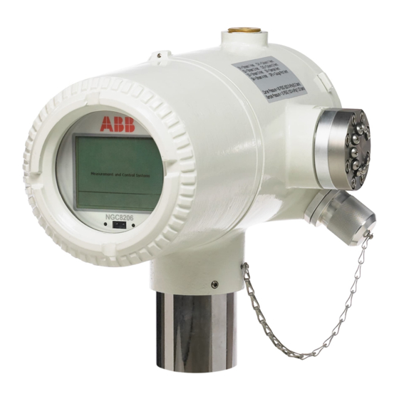
— 1.Product description Overview The ABB Natural Gas Chromatograph (NGC) and Process Gas Chromatograph (PGC) continually analyze natural gas or process gas streams on-site, determine composition and calorific value, and store the analysis information. System components This compact device requires minimal installation time and is configured and calibrated at the factory. -
Page 11: Principle Of Operation: Sample Processing
Figure 1-2: Typical multi-stream installation Principle of operation: sample processing To process a sample, a gas sample is extracted from the pipeline. The sample conditioning module removes any particulates or liquids entrained in the sample. The sample conditioning module also acts as a bypass loop to ensure that sample lag time is minimized. -
Page 12: Analyzer Standard Hardware Features
Aluminum Alloy with white polyester powder coating. Explosion-Proof, see specification sheet for certifications. Installation time Requires 2-3 hours for installation, minimum 8 hours run time for repeatability. Mounting Pipe run, free-standing pipe, shelf, and environmental enclosure NGC8200 and PGC1000 Width Height Depth Weight dimensions 9.5 inches 8.82 inches... -
Page 13: Cast Aluminum Enclosure
Figure 2-5 show the outline dimensions of the NGC8200 and PGC1000. The end caps have precision-engineered threading. The enclosure and all fittings, including feed- through, MMI connection, and breather, are tested to Nema/Type 4X. Unauthorized removal of the end caps is protected with a 1/16” hex socket set screw on each end cap. -
Page 14: Exterior Enclosure Dimensions
Figure 2-2: NGC8200 and PGC1000 enclosure face Figure 2-3: NGC8200 and PGC1000 enclosure left side 1 4 | N G C8 20 0 A N D PG C 10 0 0 US ER MA N UA L | 21 01 51 0MN A H... - Page 15 Figure 2-4: NGC8200 and PGC1000 enclosure right side Figure 2-5: NGC8200 and PGC1000 enclosure underside 21 01 51 0MN A H | NG C 82 0 0 A N D P GC 10 00 US ER MA NUA L | 1 5...
-
Page 16: Feed-Through Assembly
Feed-through assembly Independent sample streams are connected to the analyzer directly to the feed-through assembly (see Figure 2-6), or through an optionally installed sample conditioning module. The feed-through assembly also serves as the connection for carrier gas and calibration streams. Figure 2-6: Analyzer feed-through assembly NOTICE –... -
Page 17: Gc Module
The analytical module comes in two configurations: 12 VDC and 24 VDC. Figure 2-7: Analytical module 2.4.1 GC module Figure 2-8 shows the GC module with the oven wall removed. The module has the following components: columns, chromatographic valve, and GC module circuit board. The valve controls the flow of gas within the system. -
Page 18: Digital Controller Assembly With Vga Display
The analytical processor board has two status LEDs used for troubleshooting. The red LED indicates that the board is powered on. If the board is powered down by the digital controller, or has no power, this LED is off. The yellow LED indicates that the analytical processor's CPU has initiated its program successfully and is controlling its processes as directed by the digital controller. - Page 19 The display board provides a VGA monochromatic display to monitor the process and results. It also provides six magnetic switches to allow a user to navigate through various screens of data and control the processes (stop operation, start operation, and calibrate). Navigate screens using the display magnet.
- Page 20 Figure 2-11: NGC VGA display screen 2 0 | N G C8 20 0 A N D PG C 10 0 0 US ER MA N UA L | 21 01 51 0MNA H...
-
Page 21: Termination Board
Termination board The termination board provides ports or terminals for power, internal or external communication, and I/O connections (Figure 2-12). It features transient protection, a voltage regulator for the digital controller, positive temperature co-efficient fuses (PTC) and many other safeguards to protect the remainder of the system from electrical damage. -
Page 22: Local Communication Options
Local communication options The analyzer supports local communication for operator access through an explosion-proof port MMI port. The available standard option is a USB port. An RS-232 port is optional (note that this is considered a legacy interface with a lower communication speed; additional adapters may be needed for connection). -
Page 23: Compressibility Options
Normalized components Un-normalized total Ideal Btu/CV Real Btu/CV: wet (inferior CV) and dry (superior CV) Relative density (specific gravity) Density Wobble index: dry Btu (superior CV) Alarms Stream averages Last 840 hour averages ... -
Page 24: Security
Supported serial protocols operate at 1200, 2400, 4800, 9600, 19200, 38400, 57600 and 115200 baud rates. The TCP/IP protocol is supported on the Ethernet interface at 10/100 Mbps. Security The analyzer supports security options to prevent unauthorized access. Security can be configured by enabling the hardware security switch and by configuring the user interface (PPCU32) with access codes. -
Page 25: Plan For Installation
If applicable, inspect calibration and carrier gas cylinders to be certain they are correct for the installation. If there is any damage, or if there are noticeable defects, notify a local ABB representative. Keep all shipping materials as evidence of damage for the carrier’s inspection. ABB will arrange for immediate repair or replacement. -
Page 26: Pipe Saddle Installation For Pipe Saddle Mounting
Materials: One 2 inch pipe with flange One 2 inch pipe coupling One 2 inch mounting pipe (installed). Length is dependent upon final desired analyzer height. To install a mounting pipe: Select a location to install the mounting pipe that allows easy access and is close to the sample probe. -
Page 27: Analyzer Installation
One 2 inch mounting pipe. Length is dependent upon final desired analyzer height. One 2 inch pipe with flange (optional) One 2 inch pipe coupling (optional) To mount the shelf: Locate the wall position where the analyzer is to be mounted. The shelf should be positioned high enough on the wall so that all components are accessible to service personnel. -
Page 28: Sample System Installation
This allows screen visibility, access to the feed-through assembly and the termination panel located in the rear of the housing. For the shelf-mounted devices, the device would be oriented with the feed-through assembly also facing forward. Sufficient clearance is required when mounted near an inside corner. Secure in place by tightening the hex socket set screw, located in the neck of the device, using a 1/8 inch hex wrench. -
Page 29: Maintaining Phase
4.4.4 Sample probe installation ABB recommends the use of a sample probe to extract the sample from the process stream. A probe is essential in supplying a representative sample to the analyzer. Without a probe, analytical accuracy will be negatively impacted and more maintenance will be required on the analytical system. -
Page 30: Sample Conditioning Modules
IMPORTANT NOTE: The sample probe pipe coupling should be located on the top of the meter run but may be mounted vertically or horizontally. Materials: ¾ inch NPT pipe coupling (previously installed) Sample probe (configuration to be determined by the technician based on installation and local codes.) ... -
Page 31: Table 4-1: Sample Conditioning Module Descriptions
Figure 4-10: Available sample conditioning modules Table 4-1: Sample Conditioning module descriptions Part Number Description 2102024-001 Designed for sample point distances greater than 10’ (3 m) and less than 150’ (50 m) with known particulate and liquid contamination. For stable gas samples containing pipe scale and other solid contaminates and possibly minor amounts of liquid contamination. - Page 32 Figure 4-11: Single and multiple stream sample conditioning assemblies Figure 4-12: Single stream conditioning module dimensions 3 2 | N G C8 20 0 A N D PG C 10 0 0 US ER MA N UA L | 21 01 51 0MNA H...
- Page 33 Figure 4-13: Multiple stream conditioning module dimensions 4.4.5.2 Install the sample conditioning module Materials: Single or multiple module mounting kit One .312 x 2.5 x 3.62 x 1.5 U-bolt Two 5/16 inch SST split washers Two 5/16 inch SST flat washers ...
-
Page 34: Sample Line Connections
IMPORTANT NOTE: When installing the module bracket inside of the ENC82S small environmental enclosure, the mounting bracket must be installed upside down to allow for required space. Otherwise, the module bracket installed inside of the ENC82L large environmental enclosure should be oriented as shown in Figure 4-11. - Page 35 Figure 4-15: Sample conditioning module line connections IMPORTANT NOTE: Tube, ferrule and nut should always enter the connection at a right angle. If necessary, install the reducer into the sample probe output fitting. Install the ferrule and nut onto one end of the sample tubing. Insert the tubing with the ferrule into the reducer/sample probe output fitting.
-
Page 36: Carrier And Calibration System Installation
17. Repeat for each sample stream. 18. After securing tubing, check for gas leaks. Carrier and calibration system installation The procedures in this section wire the Digital Inputs (DI) to the calibration and carrier gas regulator assemblies. The examples show the DI1 used for the calibration gas and the DI2 for the carrier gas. For ease in wiring, you may remove the modular terminal connector J2 from the terminal board. -
Page 37: Calibration Gas Regulator Installation
Carrier regulator assembly with low pressure switch (see Figure 4-17) Installed carrier gas cylinder To install the carrier gas regulator: Remove the protective cap from the high-pressure inlet, if required. Insert the ferrule on the regulator high-pressure inlet into the carrier gas cylinder outlet. Screw the nut onto the thread and tighten. - Page 38 Materials: Calibration blend regulator assembly with low pressure switch (see Figure 4-19) Installed calibration gas cylinder To install the calibration gas regulator: Remove the protective cap from the high-pressure inlet, if required. Insert the ferrule on the regulator high-pressure inlet into the calibration gas cylinder outlet. Screw the nut onto the thread and tighten.
-
Page 39: Carrier Gas And Calibration Gas Line Connections
4.5.5 Carrier gas and calibration gas line connections The following procedures describe the steps for connecting the external carrier gas and calibration gas lines from the respective regulators to the feed-through assembly on the analyzer. They are applicable for both a meter run and an environmental enclosure installation. These instructions assume that the regulators and gas cylinders have previously been installed. -
Page 40: Vent Lines Connections
12. Locate the ¼ inch low pressure output fitting on the installed pressure regulator on the calibration gas cylinder. 13. Measure and cut the 1/16 inch SST tubing to the required length. 14. Make the necessary bends in the tubing to ease the installation of the ferrule and tubing into the analyzer and pressure regulator. -
Page 41: Security Seal
Figure 4-22: Vent line connections on feed-through assembly Security seal For some installations, it may be desirable to attach a security seal on the enclosure front and rear end caps. To accommodate seal, note the holes located in the tab located on each end cap (see Figure 4-23). -
Page 42: Wiring
Wiring This section describes the wiring required to connect external devices with serial interfaces and the power supply. DANGER – Serious damage to health / risk to life. Do not begin wiring unless the area is known to be non-hazardous. Wire for serial communication The analyzer’s Serial Ports 1 and 2 (J8 and J10) support RS-232, RS-422 or RS-485 communication. -
Page 43: Power Supply Requirements
The example shows the analyzer’s power terminal (J1) wired to the isolated 12 Vdc power supply. Refer to this figure when reviewing the following sections. Figure 5-1: Example of analyzer wiring 5.2.1 Power supply requirements Review the following requirements before powering the analyzer. Also see Table 2-1: Analyzer specifications. -
Page 44: Other Considerations
Table 5-2: 12 VDC battery power supply system maximum cable lengths Model Min. batt Unit 10 6 mm 4 mm 2.5 mm 1.5 mm option voltage see note see note see note 12 VDC 12.00 78.28 49.44 30.97 19.43 90.03 60.17 37.42 22.92... -
Page 45: Startup
For additional or advanced configuration options, click Help on the PCCU32 screens for the analyzer. Download PCCU32 from the ABB website The latest PCCU version is available on the ABB website. This procedure describes how to locate and download the latest PCCU installation package. Always review release notes for new features or bug fixes before installing and using new PCCU versions. - Page 46 Figure 6-1: ABB Upstream home page On the PCCU page, scroll down and select the Downloads tab (Figure 6-2). Figure 6-2: PCCU page - document downloads On the PCCU Downloads page, scroll down on the left menu of available documents, locate, and...
-
Page 47: Install Pccu32
PCCU32 must be installed in the PC or laptop that connects to the analyzer for configuration and operation. This procedure assumes that the desired PCCU32 installation package has been downloaded from the ABB website and stored in a local folder as described in section 6.1 Download PCCU32 from the ABB... -
Page 48: Establish Initial Local Communication
To install: Locate the downloaded compressed file on the PC or laptop. Unzip the downloaded installation file and save extracted files in desired folder. Open created folder. Double-click Setup.exe to run the installation program. Follow the screen prompts during installation. Click Finish when installation completes. -
Page 49: Table 6-1: Cable For Usb Connection
Figure 6-5: Cable for USB connection Table 6-1: Cable for USB connection Host system interface type Required cabling termination (connectors) ABB part number or adaptors USB 2.0 Type A receptacle USB 2.0 Type B plug to USB 2.0 Type A plug... -
Page 50: Connect Using Rs-232 Port
® /1 converter (Figure 6-11) is recommended and can be purchased from ABB (part number 1801382-001). Contact technical support to order or for more details. See Table 6-2. 5 0 | N G C8 20 0 A N D PG C 10 0 0 US ER MA N UA L | 21 01 51 0MN A H... -
Page 51: Table 6-2: Required Cables For Connection With Mmi Port
Edgeport ® /1 converter Table 6-2: Required cables for connection with MMI port Host system (PC/Laptop) Required cabling termination (connectors) or ABB part number port type adaptors Legacy serial (RS-232) 1 cable/adapter required: Serial DB-9 (9 POS, interface, DB-9 female connector) to circular military cable (referred... -
Page 52: Connect Using Ethernet Port
On the System Setup tab, under PCCU Connect Method, click Serial port. (Figure 6-12). Select the port from the PCCU Com. Port drop-down list. Legacy serial interfaces are typically identified as COM1 or COM2. Select the port used for the connection. Figure 6-12: PCCU system setup (MMI communication) Click Close to exit connection setup. -
Page 53: Table 6-3: Ethernet Cabling For Local Connection
6.3.3.1 Cabling for connection to operator laptop The analyzer’s Ethernet port does not have the ability to autoconfigure for cable type. Local operator connection to the analyzer’s Ethernet port requires a crossover Ethernet cable. Table 6-3 shows details. Table 6-3: Ethernet cabling for local connection Host system (PC/Laptop) Required cabling termination (connectors) Maximum distance... - Page 54 Figure 6-15: IP configuration for host system (automatic addressing) 6.3.3.3 Set up PCCU32 and connect This procedure assumes that the default Ethernet configuration is intact. The analyzer has a default IP address assigned at the factory (169.254.0.11). To configure PCCU32 for TCP/IP communication: Connect an Ethernet cross-over cable between the PC and analyzer.
-
Page 55: Power On Sequence
Figure 6-17: PCCU setup for local Ethernet communication Click Close to close connection setup. Click Entry on the PCCU32 menu bar to connect to the device. Click the Entry icon on the PCCU32 toolbar to connect to the device. If unable to connect, see section 8.6 Basic Ethernet connection troubleshooting. - Page 56 IMPORTANT NOTE: Additional diagnostics configuration and scheduling options are available. Click Help on the Diagnostics screen for additional details. Figure 6-19 shows the Diagnostics tab as shown from the Startup Wizard. In this example the analyzer has passed all tests. The following tests are performed: ...
-
Page 57: Startup Wizard
IMPORTANT NOTE: Depending on ambient temperatures, reaching the desired oven temperature could take up to an hour. During this time, you can follow the Startup Wizard as described in section 6.5 Startup wizard and enter information as prompted. 6.4.2.3 Processor control test This test contains three test areas: column 1 carrier pressure, column 2 carrier pressure, and oven temperature. - Page 58 Figure 6-21: Startup Wizard Follow the prompts in the Wizard. The wizard may run concurrently with the Diagnostics. Follow the wizard to complete configuration even if the diagnostics are still running. IMPORTANT NOTE: As each wizard screen is displayed, its associated help topic also displays (Figure 6-22).
-
Page 59: Set Up The Station
6.5.1 Set up the station At the Startup Wizard, click Next. The Station Setup tab displays (Figure 6-23). Figure 6-23: Station setup Enter the Station ID (10 alphanumeric digits) and Location (24 alphanumeric digits). See Table 6-4. The Station ID should be a unique identifier from other analyzers. Verify the date and time;... -
Page 60: Table 6-5: Stream Setup Screens
Figure 6-24: Stream Setup (Stream 1) When all the desired changes have been made, click Send and then Next to move to the next screen. Complete the configuration at each screen presented and click Next. When the last screen for the stream is completed and you click Next, the Stream Setup tab appears again for the next stream. -
Page 61: Set Up Calibration
Calculation Settings Value Current Calculation File GPA-2172-1996(AGA8), ISO-6976-1995, etc. See note 1. Sum IC5 and NeoC5 No (default), Yes C6+ Index Split Mode. Select one of the 3 following options: See note 2. User-defined with C6+ Reported (Default). The selection will use what the user enters on the C6+ split ratios. -
Page 62: View Diagnostics
Change the Calibration Cycles Average and Purge Cycles, if required. The default Calibration Cycles Average is 3 and the default Purge Cycles is 2. Enter calibration cylinder blend information in the component concentration table: Update the value for each component in the % Blend column. Ensure that the Total Mole equals 100%. NOTICE –... -
Page 63: Update Configuration
Figure 6-27: Stream Sequence When all desired changes have been made, click Send and then Next to move to the next screen. IMPORTANT NOTE To enable or disable streams after completion of diagnostics, select Stream Sequence from the Analyzer Operation screen. It is recommended that the diagnostic stream test be performed on streams enabled after initial diagnostics. -
Page 64: Analyze The Calibration Stream
Figure 6-28: Save initial configuration Click Send and then Next to move to the next screen. 6.5.6 Analyze the calibration stream This procedure determines if the analyzer provides accurate composition analysis of the calibration gas blend. If composition analysis does not reflect the expected composition in the blend, the analyzer requires calibration. - Page 65 Figure 6-29: Run the calibration stream (Stream 4) Figure 6-30: Calibration stream analysis running Allow the stream to process for two or three cycles (approximately 10 to 15 minutes). During the final cycle, change the next mode to Hold. When the device completes the current cycle, it will enter hold mode.
-
Page 66: Enable/Disable Streams
IMPORTANT NOTE: There will not be any comparisons for C6+ individual components. There may be values in the Normalized column for hexane through decane, but this is based on the C6+ configuration entered in Stream Setup. For comparison purposes, use the components called heavies. -
Page 67: Run Analysis Process Streams
Click Send. If you were trying to complete the wizard return to the Analyze Cal Stream tab. Click Next to Run Analysis streams. Follow steps in section 6.5.8 Run Analysis Process streams. 6.5.8 Run Analysis Process streams At the Analysis Process Streams tab, select Run on the left side of the screen (Figure 6-33) to begin the first sample stream in the sequence. -
Page 68: Complete Startup
Figure 6-34: Process stream analysis running Click Next. 6.5.9 Complete startup The device should continue to cycle through all enabled streams, performing analysis and producing data. If it was determined that calibration is required, it is recommended that the device be allowed to run for at least eight hours before calibration to allow the device to stabilize. -
Page 69: Manual Peak Find
Figure 6-36: Analyzer Operation screen If completed satisfactorily, the startup Wizard should not re-appear when connecting to the analyzer again. However, should you want to review or make changes, you may re-start the Wizard by selecting the Wizard icon from the PCCU32 top menu bar (Figure 6-37). - Page 70 Chromatogram view: To view chromatograms of the last stream processed. Two chromatograms are available (switch views by selecting the tab for the desired chromatogram): The C3-C6+ chromatogram tab which shows the heavier boiling point peaks The N2-C2 chromatogram tab which show the lighter boiling point peaks The Peak Setup tab displays a table with key characteristics or parameters for each displayed component peak.
- Page 71 Click Peak Find (see Figure 6-39). If the Peak Find button is grayed out, the unit has not completed the current cycle. Wait for the cycle to complete, and when the button activates, try again. After selecting Peak Find, the Peak Setup screen should display. Figure 6-39: PCCU Operation screen In systems with newer software, observe what is displayed on the Peak Setup screen.
- Page 72 Figure 6-40: Peak Find screen for C3-C6+ chromatogram (heavies) Figure 6-41: Peak Find screen for N2-C2 chromatogram (lights) 7 2 | N G C8 20 0 A N D PG C 10 0 0 US ER MA N UA L | 21 01 51 0MNA H...
-
Page 73: Troubleshoot Peak Find
6.6.1 Troubleshoot peak find Table 6-6 lists some potential problems that may occur during peak find, their causes and recommended solutions. IMPORTANT NOTE: When making parameter changes, make sure you select the correct component on the table (correct component row), or the correct component set for the pressure/time duration parameters (click the C3-C6+ or N2-C2 button above these parameters). -
Page 74: Table 6-7: Suggested Carrier Pressure Setpoint Adjustment Values
Type a new value in the Carrier Pressure Setpoint field. While analyzers vary from one to the other, one PSI change will move the nC5 by 5 to 7 seconds, and C2 peak by 10 to 12 seconds. Increase pressure to decrease the time that the components elute and decrease pressure to increase the time they elute. -
Page 75: Calibrate The Analyzer
Click Run a Single Cycle. Repeat steps 1-3 as necessary. If the Cal Blend component concentrations IC5 and nC5 are similar, the peak areas should be within 3% of each other. If using ABB’s standard blend, IC5 and NC5 are approximately 0.1%. - Page 76 Select Calibration on the right side of the Operation screen. The Calibration Setup window appears. On the Setup tab, set up the blend concentrations. Figure 7-1: Set up gas concentrations Click Send. From the Operation screen, select Cal. Figure 7-2: Run calibration When the current cycle completes, the device should begin a calibration on the designated calibration stream (default is stream 4).
- Page 77 Figure 7-3: Calibration running When the calibration is complete, the device should move to the designated Next Mode. View results on the Analyzer Operation screen. The un-normalized total of the calibration stream should be between 99.5% and 100.5%. If values exceed these parameters, proceed to the Troubleshooting section.
-
Page 78: Verify Calibration Data Using Peak Find
Figure 7-5: Typical chromatograph for chromatogram-2 (lights) Verify calibration data using peak find This procedure assumes that the unit has completed calibration and moved back into Hold mode. Perform the following verification steps before moving into Run mode: Click on the Peak Find icon on the right side of the Operation screen. A chromatogram will load at the bottom of the screen. -
Page 79: Configure For Network Connection
Place the vertical line of the cursor over the small tick mark on nC5 and verify that the time in the upper right-hand corner of the chromatogram is approximately 160 seconds, within 3 or 4 seconds. Click the N2-C2 tab and verify that there are four (4) peaks: N2, C1, CO2 and C2. The first peak on the left is a composite peak of C3+. -
Page 80: Ip Addressing
Note that most network equipment can detect cable type and autoconfigure for that type (straight through or crossover). Table 8-1: Ethernet cabling for network connection System Required cabling termination (connectors) or ABB part number adaptors Network device (Ethernet Straight-through Ethernet CAT 5 cable with RJ-45 1681011 hub, switch or router) connectors at both ends. -
Page 81: Enable Ethernet And Configure Ip Parameters
Figure 8-2: Straight through Ethernet cable pinouts Enable Ethernet and configure IP parameters This procedure changes the default configuration of the Ethernet interface. If you are performing this procedure through a local connection on the Ethernet port, this connection will be lost after configuration change. - Page 82 Figure 8-4: Analyzer Communication Ports tab Select the Network tab (Figure 8-5). Ensure DHCP is set to No. Configure IP parameters: Type IP address, default gateway, subnet mask. Take note of the IP address. It will be needed later to verify network communication. Set the Network Adapter to Enable.
-
Page 83: Verify Network Connection
Reset the analyzer by pressing the Reset button located on the termination panel housed in the rear of the enclosure. WARNING – Bodily injury. Do not open or remove covers unless the area, including the internal volume of the enclosure, is known to be non-hazardous. IMPORTANT NOTE: If using DHCP, the analyzer obtains the IP parameters from a DHCP server. -
Page 84: Basic Ethernet Connection Troubleshooting
Click the Entry icon on the PCCU32 toolbar to connect to the device. 10. Ensure that the analyzer’s operation screen displays. If unable to establish connection, see section Basic Ethernet connection troubleshooting. To verify connection over network using PING: Using command line in your laptop (start cmd on the laptop). Ping the analyzer’s IP address (Figure 8-8). -
Page 85: Configure Bi-Level Security
Table 9-1: Security guidelines Recommendation Description Secure physical access Control access to the device, its internal components, and connected to the device peripherals. Secure access with Turn the onboard security switch on to enforce authentication through bi-level security switch security codes or RBAC. See section 9.1. - Page 86 To enable security: Access the analyzer’s termination board. Locate the security switch (S2). Verify that the security switch (S2) is up (UNSECURE). From PCCU entry mode, click the top node on the navigation tree. The Station Setup tab displays. Under the Security section, verify that Security Switch Status is OFF. Figure 9-2: Security switch status: Off Type a four-digit security code into Security Code Level 1.
- Page 87 Figure 9-4: Enable security on terminal board (switch DOWN) 10. On the Station Setup tab, click Re-read. Verify that the security switch status is On (Figure 9-14). Enforcement of the security codes is in effect. 11. Click Close to close PCCU32 connection with device. Figure 9-5: Security Switch Status: On IMPORTANT NOTE: PCCU32 requires the security codes the next time it attempts connection with the analyzer.
-
Page 88: Configure Role Base Access Control (Rbac)
Figure 9-6: Enter security code IMPORTANT NOTE: The analyzer may not display an error message when a user tries to write an operation without the proper security code (for example if you entered a code for read-only access); it simply does not accept value changes. If connected with remote communication or Ethernet, you cannot change the security code. - Page 89 Figure 9-7: Default Administrator role access in RBAC PCCU32 Security Editor Figure 9-8 shows the default Advanced role definitions. Note that the Advanced role does not have full access for some functions. Default access configuration for each function can be customized by changing the default setting as necessary.
-
Page 90: Default Access Roles
Figure 9-8: Default Advanced role access in RBAC PCCU32 Security Editor All users and their roles are saved in an RBAC configuration file. This file is stored in the analyzer and can also be saved on a local PC or laptop for use in other analyzers requiring the same security configuration. -
Page 91: Set Up And Create A New Rbac Security Control File
9.2.2 Set up and create a new RBAC security control file To set up a new RBAC security system: Create a security control file. Create an administrator account. Create individual user accounts and assign default roles. Create customized roles if necessary. Configure communication ports. - Page 92 Figure 9-10: Security Editor Click Yes to confirm device change to NGC. Add the Administrator user: Click Add User. Type the user name into the Name field. Type the password into the Password field. Click OK. The Users list shows the administrator name with Basic as the default role. Assign the correct role in the next step.
-
Page 93: Create Additional User Accounts With Standard Roles
Figure 9-12: Assign Administrator role to Administrator account 9.2.4 Create additional user accounts with standard roles This procedure creates new users and assigns non-administrator roles to those users. To add new users: Click Add User. Type the user name into the Name field. Type the password into the Password field. -
Page 94: Save Rbac Configuration File
Figure 9-14: Newly created user Click the Role drop-down list next to the user and select the preferred role from the list. Figure 9-15: Assign standard role to new user Repeat steps 1-2 for each new user. When all users and roles are defined, save the security configuration file as described next, in section 9.2.5 Save RBAC configuration file. -
Page 95: Save Security Configuration On The Device
Save security configuration on the device The security configuration must be saved on the analyzer to take effect. IMPORTANT NOTE: When a security file is sent to a device, the security definitions will be enforced every time you connect with the analyzer using PCCU32. The file can be modified and saved again from the Security Editor if it requires updates. - Page 96 Figure 9-18: Locate saved RBAC file Type the password for the security file: Figure 9-19: Enter security file password Click OK. Click Send to save the security file on the analyzer. Click OK at the warning. Figure 9-20: Send Security File warning Click Close to exit the Security Editor.
-
Page 97: Maintenance
Figure 9-21: Login prompt when RBAC is enabled 10 Maintenance NOTICE – Equipment damage or loss of data. As with all electronic components, use caution when handling boards. Static electricity can potentially damage board components, voiding any warranty. This chapter provides maintenance information and instructions on how to remove and install analyzer components. -
Page 98: Technical Support And Returns
See the contact information at the end of this document. If an ABB component is to be returned for repair, securely wrap it in protective anti-static packaging. Before returning a component, call for a return authorization number (RA). Affix this number to the outside of the return package. - Page 99 Figure 10-1: Component overview Figure 10-2: Analytical Module, Exploded 21 01 51 0MN A H | NG C 82 0 0 A N D P GC 10 00 US ER MA NUA L | 9 9...
-
Page 100: Spare Parts
Figure 10-3: Feed Through Assembly, Exploded 10.4.3 Spare parts Recommended spare parts depends upon whether there is a single or multiple devices at the site(s) and whether the applications are fixed applications (stocked at the factory). Balance the cost of the spares with the cost of the repair time. -
Page 101: Back Up Configuration Files
Table 10-2: Field tools Description Part Number -001 kit -002 kit Bag, ABB Nylon 11” x 6” Tool 2102304-001 • • Cutter, 1/16” Tubing 1800683-001 • Extractor Tool, IC 8-24 Pin 1801690-001 • • Hex Key, Set 1/16-5/16 (12 Pcs) T10790 •... - Page 102 To update: Click the 32 Bit loader icon on the PCCU top menu. Figure 10-4: Select 32-bit loader Click Yes at the warning if you have backed up your device data. If you have not backed up the analyzer, see section 10.6 Back up configuration files.
- Page 103 Select Reload. Select the following three reload options: Shutdown Flash, Download Flash, and Start Flash. Verify that the Network IP address in the Connection field (bottom, left of the screen) is the address of the device you intend to update. Click Start.
-
Page 104: Restore Configuration Files
Figure 10-7: Load the OS Verify that the screen displays the message: "Operation complete". Click Close to exit the 32-bit loader. The connection with the device using Ethernet closes and the home PCCU screen displays. Note that there is no connection with the device. Figure 10-8: Home PCCU Screen (disconnected from device) 10.8 Restore configuration files... -
Page 105: Reset Procedures
In PCCU, go to the Operate drop-down menu. Select File Utilities then click the Save and Restore Utility. Or click the Save and Restore Utility on the toolbar. In the Save and Restore window, click Restore Station Files. When the Restore Station Files window appears, verify the default name and path for the files. -
Page 106: Cold Start
Collect data from the device. Using the Lithium Battery Status instructions in section 10.11, verify the battery status is OK before proceeding. NOTICE – Loss of data. If the lithium battery is not sufficiently charged, a warm start will become a cold start. Gain access to the rear termination panel on the analyzer by loosening the countersunk hex socket locking set screw in the rear end cap using a 1/16”... -
Page 107: Restore Factory Defaults
10.10 Restore factory defaults Occasionally, it may be necessary to restore factory defaults. This procedure should not be a normal operation. It should only be used when all other setup and troubleshooting options have been exhausted or used when a technical specialist recommends this procedure. If critical configuration data is accidentally changed or erroneous results have been produced, the device may require a reset to factory defaults. -
Page 108: Lithium Battery Status
Figure 10-12: Factory reset with loader 11. Click Close to exit the 32 Bit loader. 12. Go to Entry mode in PCCU. The device has successfully been reset if you see the Startup Wizard when you reconnect with PCCU. 10.11 Lithium battery status Prior to some maintenance procedures, especially when a Cold Start is not desirable or feasible, verify that the Lithium battery status is OK. -
Page 109: Backward Clock Change Crossing A Log Period Boundary
10.12.3 Backward clock change crossing a log period boundary This forces a log period entry for part of the log period that has accumulated since the last log period entry. This is the same as for a forward clock change crossing an hourly boundary. The analyzer advances to a new day’s data flow record and maintains the balance of the day’s data in a new record. -
Page 110: Replace The Digital Controller Complete Assembly
10.15 Replace the digital controller complete assembly Access to the digital controller assembly is gained by removing the front-mounted digital controller assembly from the analytical module. To replace the digital controller assembly: On the Analyzer Operation screen, click Hold under Next Mode. When the device completes the current cycle and enters hold, continue to the next step. -
Page 111: Replace The Analytical Module
10.16 Replace the analytical module This section presents the procedures for the removal and installation of the analytical module. The module is a completely self-contained device and is part of the analyzer. Read through all procedural steps before beginning disassembly. Verify before beginning the procedure that the replacement module is appropriately rated for the system voltage. - Page 112 Figure 10-14: Analytical Module Figure 10-15: Analytical processor board 16. Holding the new analytical module at the opening of the enclosure, reconnect jack J1 and J4 if the auxiliary heater is installed. 17. Carefully insert the module into the enclosure, rotating the module to ensure the rear components clear the manifold interface on the inside area of the feed-through assembly.
-
Page 113: Replace The Gc Module
For more information about enabling the diagnostics in PCCU, click Diagnostics and then Help. 10.17 Replace the GC Module This section presents the procedures for the removal and installation of the GC module. The module is a completely self-contained device and is part of the analytical module. Read through all procedural steps before removing the assembly. -
Page 114: Replace The Termination Panel
Figure 10-16: GC module, exploded view 13. Using the extraction tool, remove the cable connectors from J1, J2 and J3 jacks. Do not pull the connectors from the board by the wires. 14. Using a 9/64” hex wrench, loosen the mounting screw inside the center of the assembly. When loose, lift the assembly from the manifold assembly. - Page 115 To replace the termination panel: On the Analyzer Operation screen, click Hold under Next Mode. When the device completes the current cycle and enters hold, continue to the next step. Collect data from device. Back up configuration files, following the instructions detailed in the section 10.6. Using the Lithium battery status instructions, verify the battery status is ok before proceeding.
-
Page 116: Replace The Feed-Through Assembly
For more information on enabling the diagnostics in PCCU, click Diagnostics and then Help. 10.19 Replace the feed-through assembly This section presents the procedures for the removal and installation of the feed-through assembly. This assembly is located on the side of the analyzer. Read through all the procedural steps before removing the assembly. -
Page 117: Replace The Lithium Battery
19. Using a 5/64” hex wrench, tighten the feed-through set screw. 20. Insert the mounting screw into the analytical module. 21. Holding the analytical module at the opening of the enclosure, reconnect jack J1 and J4, if the auxiliary heater is installed (see Figure 10-15). -
Page 118: Replace Frit Filters
Figure 10-19: Primary Component Side Digital Controller Board 10.21 Replace frit filters When replacing the filter as part of a regularly scheduled maintenance plan, it will most likely not require that the sample lines be removed from the external plate. When replacing the filters as a troubleshooting measure, remove the sample input lines and use compressed air to clear the pathway. -
Page 119: Replace The Feed-Through Interface Gasket
Figure 10-20: Feed-through assembly, exploded view If the filters appear soiled, it will be necessary to remount the external plate and remove the input lines. To remove the input lines, continue to the next step; otherwise, move to step 9. Using a ¼”... -
Page 120: Replace The Feed-Through Manifold Gasket
Remove the 8 ¼” hex socket mounting screws. 10. Remove the damaged gasket from the internal plate. 11. Clean the gasket area on the internal plate using a clean, dry lint-free cloth before placing the new gasket on the internal plate. The gasket is keyed to ensure that it is placed correctly. The gasket should not cover any holes in the internal plate. -
Page 121: Replace The Termination Panel To The Digital Controller Cable
IMPORTANT NOTE: Note that since power was removed from this device, the analyzer will perform startup diagnostics and stabilize. If the user has disabled the startup diagnostics, it should be enabled and power cycled to the device. If the power has been withheld from the device for an unknown or lengthy period of time, a complete startup should be performed. -
Page 122: Replace The Analytical Processor To The Termination Panel Cable
IMPORTANT NOTE: Note that the termination panel to digital controller ribbon cable pin 1 wire is not red. On the digital controller board, the red edge (pin 1) of the cable should plug onto pin 50, the right side of the plug. The plug is keyed; do not force plug into connector. 22. -
Page 123: Troubleshooting
The startup tests may also be performed on a regular schedule. See the PCCU help files for more information on scheduling diagnostics. IMPORTANT NOTE: ABB performs extensive testing on each analyzer prior to shipment, and each device is factory-calibrated using our standard calibration blend. -
Page 124: Oven Temperature Test
Verify that the GC module is tight and that the cables are correctly installed and not damaged. Reassemble the device and restart diagnostics. If the device continues to fail, replace the entire analytical module and return to ABB for repair or replacement. 11.1.4 Stream Test The stream flow diagnostics test the stream pressure at different conditions as listed below. -
Page 125: Troubleshooting Alarms
Additional troubleshooting steps may be provided by technical support in an effort to reduce down time. Additionally, it may be desirable to return a module to ABB for testing and/or repair. This section focuses on determining what has caused an alarm following normal operation. The analyzer has a built-in list of alarms, some of which are user-configurable. -
Page 126: Alarm Definitions
Fault Indicates that a malfunction exists that may affect the operation of the device and most likely will provide unexpected results. The fault will keep any affected streams from having their data updated. However, a fault does not stop a scheduled or manually initiated calibration from occurring;... -
Page 127: Sample Pressure Alarm
Perform startup diagnostics. If the carrier pressure regulator 1 and 2 tests both pass, continue to the next step. Perform the Column Vent Pressure Test (see section 11.3.1) for both column vent 1 and column vent 2. If either test failed, proceed to the next step. 10. -
Page 128: Digital-Analog Board Communication Error Alarm
11.2.6 Digital-Analog Board Communication Error Alarm This alarm indicates a communication error between the digital board and the analytical processor board. Verify the cable connectors are firmly and correctly connected to both the digital and analytical processor boards. To troubleshoot digital-analog board communication error: In the alarm log, check the frequency of the error. -
Page 129: Calibration Rf Percent Error Alarm
To troubleshoot calibration CV percent error: On the Analyzer Operation screen, click Hold under Next Mode. When the unit completes the current cycle and enters hold, continue to the next step. Compare the calibration blend concentrations to the calibration blend concentrations listed on the Calibration Setup screen. -
Page 130: Low Carrier Gas Cylinder (Di1) Alarm
11.2.14 Low Carrier Gas Cylinder (DI1) Alarm This alarm indicates the carrier gas cylinder pressure is below the threshold. To troubleshoot low carrier gas cylinder (DI1): Verify that the carrier gas cylinder regulator low pressure switch threshold is set around 90 PSIG. -
Page 131: Cpu Loading Alarm
Replace the GC Module. 11.2.20 CPU Loading Alarm This alarm indicates the processor is being overloaded. An occasional spike in processor loading is to be expected. Multiple occurrences are not field-repairable. To troubleshoot CPU loading: View the alarm history for multiple occurrences. If an occasional warning is registered, this is not a problem. -
Page 132: Stream Un-Normalized Total
On the Analyzer Operation screen, click Hold under Next Mode. When the device completes the current cycle and enters hold, continue to the next step. When the device enters hold, select Peak Find from the Analyzer Operation screen. Select Run Manual PF. -
Page 133: Feed-Through Assembly Blockage Test
10. If the pressure decreases slowly, close the sample shutoff valve and return to the troubleshooting alarm instructions. The test has failed. 11.3.3 Feed-through assembly blockage test To troubleshoot feed-through assembly blockage: Remove the feed-through assembly from the analyzer (see section 10.19). If testing from the pressure regulator 1 or 2 alarms, continue to steps 3 and 4. -
Page 134: Equipment Isolation Test
Verify that there are no other devices that may drop an excessive voltage across them in the power supply circuit (to the analyzer) like a fuse, diode or a barrier device, etc. Correct and retest as necessary. Disconnect the power supply cable at the analyzer termination panel J1. Measure the power supply cable voltage at the connector and compare with the recommendations (see Table... -
Page 135: Serial Communications Troubleshooting
Was the damaged cable found? If yes, replace the appropriate cable. 10. If not, see section 10.16 to replace the module. 11. Reinstall the analytical module. 12. Reinstall the digital controller assembly. 13. If disconnected during a procedure, reconnect the J1 power supply connector to the termination panel. - Page 136 J8–Port 1 J10–Port 2 No Connection No Connection No Connection No Connection 1 3 6 | N G C8 20 0 A N D PG C 1 00 0 US ER MA N UA L | 21 0 15 10 MNA H...
- Page 137 We reserve the right to make technical changes or modify the contents of this document without prior notice. With regard to purchase orders, the agreed particulars shall prevail. ABB does not accept any responsibility whatsoever for potential errors or possible lack of information in this document.
Need help?
Do you have a question about the NGC8200 and is the answer not in the manual?
Questions and answers