ABB NETA-21 User Manual
Remote monitoring tool
Hide thumbs
Also See for NETA-21:
- Installation and startup manual (24 pages) ,
- Setup instructions (68 pages)

Subscribe to Our Youtube Channel
Related Manuals for ABB NETA-21


Summary of Contents for ABB NETA-21
- Page 1 Remote monitoring options for ABB drives, converters and inverters User’s manual NETA-21 remote monitoring tool...
- Page 3 User’s manual NETA-21 remote monitoring tool Table of contents 1. Safety 4. Mechanical installation 5. Electrical installation 6. Start-up 2017 ABB Oy. All Rights Reserved. 3AUA0000096939 Rev E EFFECTIVE: 2017-06-12...
-
Page 5: Table Of Contents
Layout of the NETA-21 and the NEXA-21 ....... . . - Page 6 TCP and UDP service ports ..........47 In-bound network services on the NETA-21 ....... 47 Out-bound network services on the NETA-21 .
- Page 7 Firmware admin ........... . . 64 User .
- Page 8 Configuring the NETA-21 for reporting ........
- Page 9 How to update the NETA-21 firmware ........
- Page 10 Product training ............195 Providing feedback on ABB Drives manuals ....... . 195...
-
Page 11: Safety
Safety 11 Safety What this chapter contains The chapter contains the warning symbols used in this manual and the safety instructions which you must obey when you install or connect an optional module to a drive, converter or inverter. If you ignore the safety instructions, injury, death or damage can occur. Read this chapter before you start the installation. -
Page 12: Safety In Installation
12 Safety Safety in installation These warnings are intended for all who install or connect an optional module to a drive, converter or inverter, and need to open its front cover or door to perform the work. WARNING! Obey these instructions. If you ignore them, injury or death, or damage to the equipment can occur. -
Page 13: Introduction To The Manual
, SW version 2.31 or later. Compatibility The NETA-21 remote monitoring tool is compatible with various types of ABB drives, wind turbine converters and solar inverters. The ABB drives compatible with NETA 21 are shown in the below table:... -
Page 14: Target Audience
Note: Later in this manual, term drive substitutes for string drive/converter/inverter. Target audience The reader is expected to have basic knowledge of electrical fundamentals, electrical wiring practices and how to operate the drive. Purpose of the manual The manual provides information on installing, commissioning and using the NETA-21. -
Page 15: Before You Start
• Tools explains how to manage NETA-21 firmware, factory settings and software packages. • Backup and restore describes the backup and restore functions of the NETA-21. -
Page 16: Terms And Abbreviations Used In This Manual
Network service which allows automatic detection of other Ethernet-based ABB products (eg, the FENA-11) in a local network. In addition, enables finding the NETA-21 in the network where the PC tool has been connected. Portlet Panel for text and controls within a page or tab. Some portlets can be moved around, added and removed, eg, on the front page. -
Page 17: Abbreviations
Introduction to the manual 17 Abbreviations Abbreviation Explanation Distributed Drives Communication System, an optical fiber device access method for drives and inverters (for example, ACS800 and PVS800) DDNS Dynamic Domain Name System DHCP Dynamic Host Configuration Protocol, a protocol for configuring servers in a network File Transfer Protocol provides an unsecure way to access files in a network FTPS... - Page 18 18 Introduction to the manual...
-
Page 19: Overview
This chapter contains a short description of the NETA-21. NETA-21 remote monitoring tool The NETA-21 remote monitoring tool is used for browser-based remote monitoring of ABB drives via Ethernet. Multiple drives can be connected to the network by using a panel bus or through the fiber optic channel of the NEXA-21 extension unit. -
Page 20: Neta-21-Specific Features
• External (Internet access) • Automatic or fixed IP configuration • Easy point-to-point access to the NETA-21 with a PC (no need to change the IP address of the PC) • Email reporting of events and parameter history logs •... -
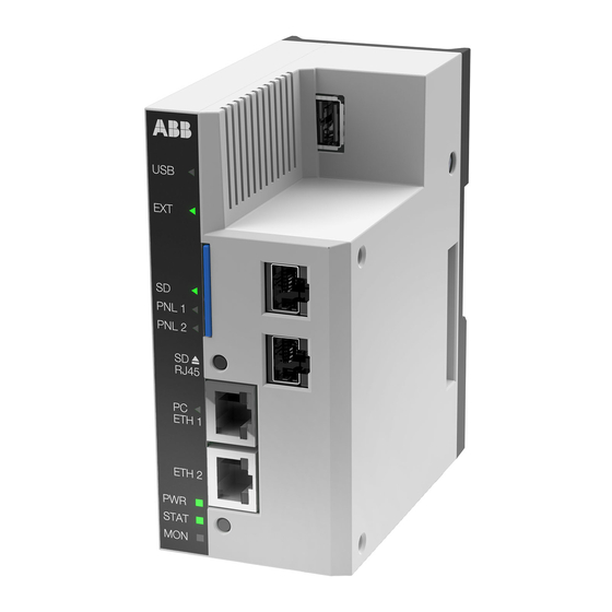
Page 21: Layout Of The Neta-21 And The Nexa-21
Overview 21 Layout of the NETA-21 and the NEXA-21 The following figures describe the front and bottom layout of the NETA-21 and the NEXA- NETA-21 NETA-21 and NEXA-21 Front panel labeled with a black sticker and equipped with indicator LEDs PWR, STAT, MON –... -
Page 22: Hardware And Software Requirements Of The Pc
Firmware versions 2.22 and beyond have been tested only with Internet Explorer 9 and later. Most mobile phone and tablet browsers are also capable of showing the NETA-21 web pages, but displayed elements are not fully optimized for the touch screen use. -
Page 23: Mechanical Installation
Mechanical installation 23 Mechanical installation What this chapter contains This chapter contains a delivery checklist and instructions on mounting the NETA-21. WARNING! Follow the safety instructions given in this manual and the drive documentation. Unpacking and examining the delivery The option package for the NETA-21 contains: •... -
Page 24: Installing Nexa-21 To Neta-21
24 Mechanical installation Installing NEXA-21 to NETA-21 1. Remove the plastic cap from the connector in the NETA-21. 2. Press the NEXA-21 against the NETA-21. 3. Tighten the grounding screw. Do not use excessive force. Installing the NETA-21 1. Protect the devices from the drilling dust. -
Page 25: Electrical Installation
IP address • instructions on connecting the NETA-21 to the drive and to the Ethernet network. WARNING! Only qualified electricians are allowed to carry out the work described in this chapter. Follow the instructions in section Safety in installation. -
Page 26: Grounding
26 Electrical installation Grounding Use a grounding clip to connect the ground of the NETA-21 to the mounting rail. Make sure that he mounting rail is grounded to a noiseless ground. If the rail is not mounted on a properly grounded base, use a separate grounding conductor. The conductor must be as short as possible and its cross-sectional area must be 6 mm at least. -
Page 27: Connection Over The Ethernet Tool Network With An Ethernet Adapter Module
Settings –> Device interfaces –> Ethernet –> Settings –> Background scan. Note: If the ETH1 and ETH2 ports of the NETA-21 are connected, they must be configured to use different sub-nets (different IP addresses under non-overlapping netmasks). -
Page 28: Data Link Connections - Drive With The Rdcu Control Unit
You can connect the NEXA-21 also to ch0 if the maximum speed of the communication does not increase above 1 Mbit/s. The default NETA-21 settings for a network are ring topology and 1 Mbit/s communication speed. With these settings, the NETA-21 can normally auto-detect drives connected to an NDBU branching unit. - Page 29 Electrical installation 29 Note: Use the same speed setting in the NETA-21, NDBU branching unit and drives. ABB drive, ABB drive, converter or converter or inverter inverter RDCU RDCU RDCO RDCO NETA-21 NDBU-x5 V106 V105 ETH1 V104 V103 V102 MSTR...
-
Page 30: Connection Via The Eia-485 Port With A Modbus/Rtu Adapter Module
EIA-485 port EIA-485 port T = Termination The X3 EIA-485 connector for a Modbus network is located at the bottom of the NETA-21. See the bottom layout in section Layout of the NETA-21 and the NEXA-21. The EIA-485 (RS-485) cabling requires a shielded dual twisted pair cable. The nominal impedance of the cable must between 100…150 ohm. -
Page 31: Switching On The Bus Termination
Electrical installation 31 Switching on the bus termination To avoid signal reflection, add 120-ohm termination to the last devices at each end of the bus line. Termination Termination Termination Termination activated deactivated deactivated activated EIA-485 device EIA-485 device EIA-485 device EIA-485 device Term. - Page 32 32 Electrical installation...
-
Page 33: Start-Up
Link-local address assignment (RFC 3927) or Automatic Private IP addressing (APIPA). When a local PC is connected to the PC ETH 1 connector, you can set the NETA-21 as the DHCP server in the Ethernet 1 link. -
Page 34: Connecting A Local Pc To The Neta-21 In The Dhcp Server Mode
The PC ETH 1 LED shows that there is a connection (green blink = waiting, green = connected). Note: If after one minute there is no connection between the PC and the NETA-21, the DHCP server mode in the NETA-21 is set off. - Page 35 You can keep the default password by clicking the Don’t change button. Note: We recommend that you change the default password when you log on to the NETA-21 for the first time. The front page of the user interface is shown. See chapter Front page.
-
Page 36: Basic Settings
1. Go to the front page. 2. Click the Software update button. The NETA-21 searches the pages for a new version of firmware or any of the installed extra packages and shows a list of available updates. 3. Select the updates you want to install and click the Update button. -
Page 37: Changing The Password
Start-up 37 Changing the password 1. To change your password, go to Settings –> My details –> Change password. 2. Type the old password to the Old password text box. 3. Type the new password to the New password text box. 4. -
Page 38: Adding Users
38 Start-up Adding users Note: You can add users only if you have the access rights of Network admin or Tool admin. 1. To add a user, go to Settings –> Users –> Add user. The User properties panel appears on the right-hand side of the tab. The components of the tab are described in section User management. -
Page 39: Setting Date And Time
1. To set date and time, go to Settings –> Locale –> Date and time. Note: If the NETA-21 does not have the correct date and time, the stored data will also be logged with incorrect date and time stamp. -
Page 40: Setting The Location Of The Neta-21
Note: You can change the locale settings, if you have the access rights of Drive expert, Network admin or Tool admin. To set the location of the NETA-21, go to Settings –> Locale –> Location. Defining the Ethernet network settings ... -
Page 41: Initializing The Communication Between The Neta-21 And Drives Online
See the appropriate drive manuals. 5. Switch the drives off to set the channel address settings. 6. Switch the NETA-21 off or disconnect the fiber optic cable from the NEXA-21 for more than 1 minute. 7. Connect the drives to the NEXA-21. See section Communication connections. - Page 42 42 Start-up...
-
Page 43: Program Features
The main purpose of using FTP is to upload or download files between the local and remote device. The NETA-21 supports both unencrypted and encrypted (FTPS) connection. The unencrypted connection s disabled by default and works on port 21. The encrypted connection supports only explicit Transport Layer Security (TLS) encryption and works on port 990. -
Page 44: Http
PC). External plug-ins, such as Java or Flash, are not required. It is recommended to use HTTP only with a direct cable connection to the NETA-21. For all other purposes it is recommended to use the secure HTTPS. To switch from HTTP to HTTPS edit the address from http://192.168.230.1 to https://192.168.230.1. -
Page 45: Modbus/Tcp Gateway
With a normal PC and a program that supports the Modbus/TCP protocol in the same network to which the NETA-21 is connected, you can query values of parameters from the connected devices. The Modbus/TCP client configuration requires you only to specify the IP of the NETA-21 and port 502. -
Page 46: Ethernet Pc Tool Gateway
Drive Composer establishes Ethernet communication only with recognized devices such as FENA-11 and FENA-21 Ethernet fieldbus adapters. The PC tool friendly mode should be enabled in NETA-2 if NETA-21 and Drive Composer are used at the same time through Ethernet. To enable PC tool friendly mode, go to Settings –>... -
Page 47: Tcp And Udp Service Ports
SSH console for support and diagnostics. Each NETA-21 contains a factory user account with a random password. SSH access is not provided for NETA-21 end users. To disable the SSH service, go to Settings –> Tool settings –> Factory tools and deselect Enable factory login (factory support account). -
Page 48: Out-Bound Network Services On The Neta-21
NETA-21 sends outgoing NTP service packets to “pool.ntp.org” by default every hour. To configure the setting, go to Settings –> Locale –> Date and time. If no NTP server is found, the NETA-21 defaults to a manually config- ured clock setting. -
Page 49: Cybersecurity Disclaimer
ABB and its affiliates are not liable for damages and/or losses related to such security breaches, any... - Page 50 50 Program features...
-
Page 51: Front Page
Front page 51 Front page What this chapter contains This chapter describes the front page of the web UI. Parts and components of the portal The front page consists of the following parts: • application-specific toolbar (1) • navigation bar (2) •... - Page 52 Welcome instructions portlet contains instructions for the new user. To change the instruction text, go to Settings –> User interface. • Tool description portlet contains a description of the NETA-21. The description text can be changed from the settings. •...
-
Page 53: All Devices Portlet
All portlets can be minimized or closed by clicking the icons in the right corner of the portlet title bar. Version information To find out the version information of the NETA-21, click About in the navigation bar of the user interface or the corresponding icon in the application-specific toolbar. •... -
Page 54: Application Toolbar And Navigation Bar
• Settings button opens the main settings view. • Devices button opens a view showing all the devices connected to the NETA-21. • Top bar can be shrunk to a smaller size by clicking the double arrow button at the bottom right corner of the gray box. -
Page 55: Status Icons
Front page 55 The navigation bar can be hidden/unhidden by clicking the small arrow between the navigation bar and the content area or the double arrow within the Navigation title bar. Status icons In the navigation bar and application toolbar the statuses of the devices are indicated with small icons. - Page 56 56 Front page...
-
Page 57: Users
Users 57 Users What this chapter contains This chapter describes the user management. My details To see the settings of a current user, go to Settings –> My details. On the admin tab, you can change your email address, phone number, language and password. You cannot change your user name or role, even if you had an administrator role. -
Page 58: User Management
21 and Tool admin can change everything in it. Note: The NETA-21 includes a factory account for the web UI. This account is not shown in the users list. To disable the factory account, go to Tool settings –> Factory tools (see Factory tools). - Page 59 Users 59 The Users tab contains the following buttons: • Add user button inserts a new user in the list with default settings. The new user is not added to the UI until you have clicked the Create user button in the User properties panel.
-
Page 60: User Properties
60 Users User properties The User properties panel contains modifiable settings for the selected user. This panel is visible only if a user is selected from the user list. The User properties panel consists of two sub-panels: User details and User & password. The User details sub-panel inside the User properties panel contains the following components: •... -
Page 61: User Roles
External account Tool admin With the Tool admin role you have the full access rights to the NETA-21. In addition to the access rights listed for Drive expert and Network admin, the Tool admin role allows you to: •... -
Page 62: Drive Expert
62 Users If you log on to the UI as Tool admin, the front page appears as follows: Drive expert The Drive expert role includes the access rights of Guest and User supplemented with rights allowing you to: • reset and rescan drives •... -
Page 63: Network Admin
• view and change NETA-21 settings • restore settings to factory default values (software option) • see the installed software type and version of the NETA-21 • reboot the NETA-21 (software option) • view and change user interface settings •... -
Page 64: Firmware Admin
• view and change device interface settings • back up and restore the NETA-21 firmware and NETA-21 settings to/from the SD card • update the firmware of NETA-21 connected drives. If you log on to the UI as FM Admin, the front page appears as follows: User ... -
Page 65: Guest
Users 65 If you log on to the UI as User, the front page appears as follows: Guest With the Guest role you have the lowest level access rights. As Guest you can only: • change My details settings •... -
Page 66: User Interface
66 Users User interface The User interface tab is found under Settings. The text boxes on the tab can contain embedded environment variables, in other words, the value of the environment variable is shown in the text. The text may contain '{VARIABLE}' where VARIABLE means the name of environment variable on the server. - Page 67 UI. • Tool name text box shows the name of the NETA-21 (the default is the same as the tool type). This box may contain embedded environment variables. When you make changes in this box, the following places will be affected: •...
- Page 68 68 Users...
-
Page 69: Devices
This chapter describes how to manage device parameters and use data loggers. Devices tab There are two tab pages under Devices: • Devices tab lists all devices that are connected to the NETA-21. • Events tab lists events for all detected devices. The Devices tab contains the following components: •... - Page 70 70 Devices • Navigate button opens the front page of a selected device. This button is disabled if no device has been selected. If you click the arrow on the button and select Parameters or Events, you can go directly to the Parameter browser tab or the Event tab of the selected device.
-
Page 71: Device
Devices 71 Device front page Every device has its own front page which can be customized by the administrator. Every user has the same layout. The front pages are portals where the user can move, add and remove the contents. •... -
Page 72: Device Control Buttons
NETA- 21. When you reconnect the NETA-21 to the drive, use this button to resynchronize the parameters shown in the Parameter browser tab with the actual parameters of the drive. -
Page 73: Parameter Browser
The button is enabled when the associated drive has been disconnected from the NETA-21. Use the button to permanently delete the drive from the drive list of a device interface, for example, when the configuration of the system has changed. - Page 74 Parameters updated field shows how much time has gone since the parameter structures have been updated from the device to the NETA-21. The NETA-21 keeps a cached list of parameter structures, and someone else (a local user with a control panel, a PC tool user, or the monitored device itself) may have changed parameters after the last update.
-
Page 75: Parameter Properties
Devices 75 Parameter properties Open the Parameter properties panel by clicking a parameter in the Name column. The panel has two sub-panels that are visible one at a time. • Modify panel has controls to modify the parameter value. • Logging panel contains logging-specific settings and lists. - Page 76 76 Devices Spin-boxes use the minimum and maximum value limits received from the device. You cannot type the value. • Format is a drop-down list for specifying the format of a parameter value. The format can be Decimal, Hex or Binary. •...
-
Page 77: Export Of Parameters
Devices 77 • Open parameter logging history in a new tab button • Refresh button updates the log list/chart if new values have been logged. • Export the event attachment button creates a log report file to be exported. • Toggle between chart and list view button changes the view in which the logged values are displayed. -
Page 78: Import Of Parameters
When you click the Import button you are asked for an import file. The file is sent to the NETA-21 and the progress dialog box is shown. The NETA-21 supports the NETA-21, NETA-01 and DriveWindow parameter export files for importing. -
Page 79: Device Data Logger
Devices 79 Device data logger Data logger The drives connected through a DDCS protocol have a data logger or data loggers that can record data from various signals of the drive when there is no external logging mechanism active. This can be used for troubleshooting or diagnostics. Data collecting can be stopped by either a specific stop command or automatically by a triggering condition becoming true in the drive. - Page 80 80 Devices • Triggers toggle button shows the data logger trigger settings in the editor panel. • Export… button shows a drop-down list of two options: Events and Settings. • Events option exports all collected recent data log files to a compressed .zip file that can be opened with a PC.
-
Page 81: Opening A Data Logger
Devices 81 • Source column shows the source of the event. You can filter this field with a free text box. • Severity column defines the severity (or type) of the event (Detail, Notification, Warning, Fault, Severe). You can filter this field to show only the wanted event types. The columns can be sorted, hidden or filtered by clicking the header arrow, which appears when the cursor is over the header. -
Page 82: Setting Up A Data Logger
82 Devices Setting up a data logger 1. Open Datalogger 1 or Datalogger 2 (see above). 2. Click the Settings button to open the Settings sub-panel of the Datalogger configuration panel in the right-hand side of the tab. 3. From the Datalogger auto control drop-down list select Only automatic upload (data logger stops after it has finished collecting data) or Keep continuously running (data logger is started whenever the logger is initialized or filled, even if the logger was not initially running). - Page 83 Devices 83 To leave the Channel box as it is, click Cancel. 6. Remove the unnecessary monitoring parameters by selecting them and clicking the Remove selected channel icon.
- Page 84 84 Devices 7. Open the Triggers sub-panel. In this panel you can adjust: • Time step (ms): sampling rate of the data logger in the device. • Trigger conditions: multiple choices depending on the monitored device. • Trigger variable (parameter selection), Trigger level and Trigger hysteresis, if the selected trigger condition requires the values.
-
Page 85: Device Interface Settings
Device interface specific settings lets you configure communication parameters as well as fine tune device specific settings. Normally the NETA-21 configures device interfaces automatically and auto-discovers connected monitored devices. Sometimes it is necessary to rebuild the device interface to refresh the list of monitored devices. -
Page 86: Ddcs Tab
The DDCS tab contains all the devices which use the DDCS protocol and which are connected to the NETA-21 through fiber cables (via the NEXA-21). Click a device in the list to open the Device parameters panel where you can change the value of the Main status word to Not set, Dataset 2 or Dataset 11. -
Page 87: Ethernet Tab
Devices 87 Ethernet tab The Ethernet tab contains all the devices that the NETA-21 finds in its Ethernet tool network. Note: If there is an ACS880 or ACS860 drive equipped with a FENA-11/21 adapter module in the Ethernet network, the NETA-21 and the Drive composer PC tool cannot access the FENA-11/21 at the same time. -
Page 88: Modbus Monitoring Tab
Drive template is a drop-down list for the template to be used with this device. A template is a file provided by ABB that is stored under the "template" folder in the SD card or internal memory. The template selection provides also a list of other connected drives. -
Page 89: Modbus Templates Tab
Modbus templates tab The Modbus templates tab lists all the available templates from the internal memory and the SD card of NETA-21. The tool bar of the Modbus templates tab has the following buttons: • Add button allows you to add more templates. You can either import a template or can clone the parameters of a connected device. -
Page 90: Edit Modbus Templates
You can edit an existing Modbus templates or can add and edit a copy of existing default template. To edit an existing Modbus template, perform the following: 1. From the NETA-21 UI, go to Settings -> Device interfaces -> Modbus templates tab. - Page 91 Devices 91 Note: If you try to edit a default template, a confirmation message is displayed to copy the template to the SD card. Click Yes to continue. Else, click No. 3. In the Modbus Template Editor, you can edit the following: •...
- Page 92 Operation Reason No response NETA-21 cannot read any values. Value column and mask can be empty, but the parameter must be an existing parameter which can be always read if the device is con-...
- Page 93 Devices 93 Operation Reason Change Value is changed and is equal to specified value. (appears as Equal in firmware 2,27 and later) Not equal Value not equal to specified value Note: The operation names are not editable. • Value - Parameter internal value (integer). Events Events tab provides information on the custom monitored parameters that triggers the events.
- Page 94 94 Devices Event tab has the following components: • Severity: Displays the severity of the event. • Parameter: Displays the related parameter that triggers the event. • Mask - See mask field in States tab. • Operation - See Operation in States tab.
-
Page 95: Modbus/Tcp Gateway Tab
Devices 95 -Bitword: Parameters with bitwords. You can edit the bit values and texts using the Edit List button. • Index - Displays the parameter index in group.index format. Max value is 255.255 • WP - Displays whether the parameter is write protected. •... -
Page 96: Panel Bus Tab
96 Devices On selection of a drive from the list, the Device Parameters section displays settings of the selected drive as follows: • Modbus node id field represents the connection specific node ID of the drive, see chapter Modbus/TCP gateway on page 45. - Page 97 Devices 97 Modbus/TCP settings The figure below shows the Interface settings dialog box of the Modbus/TCP gateway tab. • 32-bit word order is a drop-down list for selecting the most or least significant word order for 32-bit values. There are 2 options: •...
-
Page 98: Ethernet Settings
98 Devices Ethernet settings The figure below shows the Interface settings dialog box of the Ethernet connection. With the Background scan function you can define how the automatic device discovery works. The available options are: • Disabled: Devices are not automatically discovered. •... -
Page 99: Ddcs Settings
Devices 99 Communication Mode is a drop-down list for setting the serial communication mode. The available values are the following: • 8-N-1: 8 None 1 • 8-E-1: 8 Even 1 • 8-O-1: 8 Odd 1 • 8-N-2: 8 None 2. Background scanning is a drop-down list for enabling or disabling the automatic device discovery. -
Page 100: Panel Bus Settings
• Time synchronization is a drop-down list for enabling or disabling the function. When enabled, NETA-21 will act as a clock master for the drives connected via this interface. • Connection speed (pnl1) shows the speed for the active connection. -
Page 101: Networks
Save button saves the changes to the NETA-21. When you save the settings, they are applied to use immediately. A dialog box warns that the connection to the web pages can be lost, if the IP address of the NETA-21 is changed. You can either continue or cancel the changes. -
Page 102: Test Interface
102 Networks • Import button imports the Ethernet settings from a file to the UI. • Test interface button opens a dialog which can be used for sending a ping message to a defined address. Test interface When you click the Test interface button the following dialog box appears: The Ping server dialog box contains the following components: •... -
Page 103: Ethernet Panel
Default gateway boxes. This is the default setting. When this mode is selected, the NETA-21 tries to retrieve its IP address from the DHCP server. If the DHCP address retrieval fails, the NETA-21 defaults to a “zeroconf” IP address in format 169.254.x.y where x and y are randomly selected numbers. -
Page 104: Network Status Panel
FTP are configured in the Report view. The Services tab contains the following components: • Save button saves the changes to the NETA-21. • Reset button discards all changes made by the user and restores the default settings. -
Page 105: Test Smtp Settings
Networks 105 Services/firewall settings panel, Services settings panel Mail servers (outgoing) panel are described below. Test SMTP settings The Test SMTP settings dialog box contains the following components: • From text box defines the email address of the sender. •... -
Page 106: Services Settings Panel
NetBios hostname is a text box for defining the host name for the NetBios service, which facilitates the access to the NETA-21 with a local name instead of an IP address in some local network environments. The default value is "NETA-21". -
Page 107: Mail Servers (Outgoing) Panel
DHCP server mode. HTTP/HTTPS HTTP is the default protocol setting in the NETA-21. To switch from HTTP to HTTPS edit the address from http://192.168.230.1 to https://192.168.230.1. This can also be done by selecting the Prefer HTTPS check box in Network services. -
Page 108: Starting Up The Smtp Configuration
108 Networks Starting up the SMTP configuration 1. Make sure that the NETA-21 is able to access the specified SMTP server over Ethernet. 2. Go to Settings –> Network services –> Mail servers (outgoing) and set the appropriate server settings. -
Page 109: Ftp/Ftps
Networks 109 FTP/FTPS With the NETA-21 you can access the content of the SD memory card remotely if you use the FTP protocol either through an encrypted or an unencrypted channel. Go to Settings –> Network services to enable FTP. You can enable either the encrypted (FTPS) or unencrypted (FTP) connection. -
Page 110: Dynamic Dns
The NETA-21 provides support for the Dynamic domain name system (DDNS). The Dynamic DNS service is useful when you have to access the NETA-21 with a dynamic IP, for example, when the NETA-21 is located in an isolated region where the only network access is through a 3G modem. -
Page 111: Dial-Up Function
• Password: defines the password for the DDNS service. Now you can access the NETA-21 web interface by using the registered host name. For example, if you have registered to the dyndns.org service with host name “my-neta- 21”, you can access the NETA-21 with address “my-neta-21.dyndns.org”. -
Page 112: Using A Mobile Broadband Connection
112 Networks The toolbar contains the following buttons: • Save button saves the changes to the NETA-21. • Reset button discards all changes you have made. • Export button exports the modem settings to a local file. • Import button imports the modem settings from a file to the UI. - Page 113 Networks 113 If the modem is not already available in the list, click the Search button. 4. Select the Enable dial up check box. 5. Type all necessary information in the Dial up and GPRS settings panel. 6. Click the Save button. 7.
- Page 114 114 Networks...
-
Page 115: Events
Events 115 Events What this chapter contains This chapter describes how to observe and filter events. Universal event list The Event tab is virtually omnipresent in the UI. The contents of the tab may vary slightly in different views. The following figure shows the Event tab under Home. This tab shows all events. - Page 116 Note: Filtering is applied only on the web browser side and for the visible (usually 100 latest) events only. Filtering can empty the event list even if there were matched events in the event storage of the NETA-21 (in an older event history).
-
Page 117: Contents Of The Non-Universal Event List
Events 117 Contents of the non-universal event list The non-universal event lists do not show all events. For example, the Event tab under Devices shows only device-related events. Filtering settings by columns The filtering criteria can be set separately for each column. In the heading row of the event list there are arrow icons opening a menu for setting the filtering criteria for each column. - Page 118 The column can be sorted with a search text box. • Local time column shows when the event has happened. Device events are synchronized with the NETA-21 clock. • Relative time column shows how much time has passed since the event has happened.
-
Page 119: Filtering Settings Through The Event Filter Panel
Events 119 Filtering settings through the Event filter panel The event list can be sorted by defining the filtering criteria with the Event filter panel.The Event filter panel is opened by clicking the Filter events button. Note: The Event filter panel provides more accurate search results than column filter and search options, because it initiates a search within the web UI server. - Page 120 120 Events a single page, the toolbar at the bottom of the Event tab can be used for changing pages.
-
Page 121: Reporting
For example, it is possible to save all or some parameter values periodically to an SD card or to upload them to an FTP server. In addition, you can configure the NETA-21 to send emails when a drive enters a faulted state. By default the NETA-21 stores all changed parameters and drive events to an SD card daily. -
Page 122: Configuring The Neta-21 For Reporting
122 Reporting Configuring the NETA-21 for reporting To configure the NETA-21 for reporting, specify the logging intervals of the parameters needed in the report: 1. Go to Reports –> Parameter history logging. 2. Click a parameter and select the interval in the Parameter properties panel. - Page 123 Reporting 123 The following intervals are available: • • Hour • 5 Minutes • Minute • Continuous monitor • None (in other words, no logging) The Continuous monitor logging interval was added in firmware 2.20. If you want to set the intervals for several parameters simultaneously, go to Reports –>...
-
Page 124: Creating An Email Report
124 Reporting Creating an email report To be able to use the email reporting, you must configure the SMTP settings. See section Network services. Make sure that you have set the logging intervals for the parameters (Reports –> History logger). If you have not set the logging intervals for the parameters, the reports will have no data. -
Page 125: Format Of The Email Report
Reporting 125 • To address is a tex box for defining the email recipient. To send an email to several recipients, separate the email addresses with a comma or semicolon. • E-mail subject is a text box for defining the subject of the email. •... -
Page 126: Creating An Sd Card Report
126 Reporting Creating an SD card report The NETA-21 contains three default reports: Parameter history to SD card, Event report to SD card and Backup all connected drive parameters to SD card monthly. These reports update values.db and events.db databases to the SD card when new data is logged (before firmware 2.22, .csv and .log files were stored daily by default). -
Page 127: Format Of An Sd Card Report
Reporting 127 • Store to memory card as is a selection list for specifying the formats to save reported data and events. The available options are: .csv and.log files .db database (SQLite) 6. Click the Create report button. To check that the report has been successfully sent, go to Reports –> Report events. Note: If the report does not appear on the SD card, check that the SD card is not full. -
Page 128: Db-Formatted Reports
128 Reporting The SD card report for logged data looks like in the following example. An event report looks similar except that there are more event-specific columns beginning with an ampersand “&”. DB-formatted reports SQLite files have extension .db. You can view the content of the files with any SQLite file viewer, for example, with SQLite Database Browser. -
Page 129: Creating An Ftp Report
Reporting 129 The value_cache table contains the values read for the parameters. Note: The timestamp column indicates time in microseconds since the 1st of January 1970 (so called Unix time except with microsecond precision). Creating an FTP report Make sure that you have set the logging intervals for the parameters (Reports –> History logger). - Page 130 130 Reporting Here you can select the data to be reported. See Setting the reported data. 5. Click the Output settings sub-panel and define the settings. • Enable report is a check box enabling the FTP reporting. • Create folders is check box for enabling the creation of a new folder. •...
-
Page 131: Format Of An Ftp Report
Reporting 131 Format of an FTP report The FTP reports are in the CSV format. CSV files with parameter values have extension .CSV and event data reports have extension .log (or .evt prior to firmware revision 2.20). Each report is created in a sub-folder of the folder specified in the Output settings sub- panel. - Page 132 • Site identifier is a text box to define the optional name for the site. By default, the serial number of NETA-21 is added as site identifier. 6. Click the Create report button. To check that the report has been successfully sent, go to Reports –> Report events.
-
Page 133: Setting The Report Trigger
Reporting 133 Setting the report trigger 1. To define the report trigger, go to Reports –> Settings –> Reports –> New report –> General settings. 2. From the Report trigger list, select the frequency for the report generation: • Every 5 minutes •... - Page 134 134 Reporting • Device state changed Status of a particular drive has changed. Note: You can select the drive to be monitored. • Parameter value Value or another parameter can be specified as a basis for comparison. Bitmask is ANDed to the original value before comparison. •...
-
Page 135: Setting The Reported Data
Event - To report events according to severity and category. • Logged data - To report all parameters according to the logging interval defined in section Configuring the NETA-21 for reporting. • Custom - To specify the custom data from the Reported custom data list. - Page 136 136 Reporting 3. To preview the contents of the report, click the Preview data… button. • On selecting the data type Event, the content of the report appears as shown in the below figure: • On selecting the data type Logged data, the content of the report appears as shown in below figure:...
-
Page 137: Changing The Reporting Name
Reporting 137 Changing the reporting name You can customize the reporting name for each connected device. The reporting name and the optional reporting name are added as a prefix to the logged signal names, if you have selected so (Reports –> Settings –> Signal names –> Settings, see Changing the default naming of signals). -
Page 138: Changing The Default Naming Of Signals
If you have not typed in any customized name for the trend-logged variables, the default naming is used for the parameters. 1. To define how the NETA-21 names the trend-logging variables by default, go to Reports –> Settings–> Signal names –> Settings. -
Page 139: Parameter Logging Interval Templates
NETA-21 (and after the device interface has been reset to the default settings). Use the Send template to tool… button to save a new template file to the NETA-21. Under the Logging interval templates heading you can see the list of saved templates. If you click the Run templates button, you can check some of the saved templates. - Page 140 If the fallback is set to true and there is a parameter that does not fit to the primary interval (interval attribute), the NETA-21 tires to set the logging interval of a matching parameter to the next available (lower frequency) interval during the template run.
-
Page 141: Changing The Continuous Monitor Interval
Reporting 141 The following is an example of the logging intervals template that applies an interval of 1 minute to parameter 01.01: The following is an example of the logging intervals template where the reported signal name of parameter 01.01 is changed to “percentage” only when the unit of the parameter is %: Changing the continuous monitor interval ... -
Page 142: Using Scripting For Email Reports (Custom Report)
Editing an invalid JavaScript code can lead to interruption in reporting. If the reporting freezes completely as a result of an invalid script, you need to restart the NETA-21. Before restarting the NETA-21, choose a pre-defined reporting template and save the report settings. -
Page 143: Using Scripting For Sms Reports (Custom Report)
Editing of an invalid JavaScript code can lead to stoppage of all reporting. If the reporting freezes completely as a result of an invalid script, you may have to restart the NETA-21. Before restarting the NETA-21, choose a pre-defined reporting template and save the report settings. -
Page 144: Description Of The Tabs Under Reports
Settings tab. • Import button imports a report from a file to the NETA-21. If the imported report has the same name as an existing report in the NETA-21, then the report in the NETA-21 is overwritten with the file. •... -
Page 145: Devices Tab
Reporting 145 Devices tab On the Devices tab, you can see all connected devices. There are the following three columns: • Device id: the internal name of a device. • Device name: the name assigned to a device. • Reporting name: the name used in reports for a device. -
Page 146: Parameter History Logging Tab
146 Reporting Parameter history logging tab The Parameter history logging tab shows the drive signals to be reported. By default all signals are checked for changes daily. Only changes are saved and reported to the SD card. The tab contains the following components: •... - Page 147 Reporting 147 • Parameter list shows all parameters in the selected interval. Multiple parameters can be selected at the same time. If at least one parameter is selected, the parameter properties panel is shown. The following columns exist: • Parameter name •...
-
Page 148: Report Events Data Tab
148 Reporting The available intervals are: • Minute • 5 minutes • Hours • • None • Continuous monitor. • In firmware 2.21 the logging interval for Continuous monitor is 1second. In firmware 2.23 the logging interval is adjustable between 1 … 30 s and the default value is 5 seconds. -
Page 149: Configuration Events Tab
Reporting 149 Configuration events tab To see all the modifications made to reporting settings, go to Reports –> Configuration events. The events can be filtered and sorted. - Page 150 150 Reporting...
-
Page 151: Tools
The Tool firmware tab (Settings –> Tool settings) shows the installed firmware version of the NETA-21 and enables to update the firmware of the NETA-21. Note: The NETA-21 firmware updates require an SD card with a minimum of 200 MB free space. - Page 152 (if the file is not checked, then NETA-21 does not try to install it). The check box is disabled if the firmware is older than the current firmware or if it is the current firmware.
-
Page 153: Factory Tools
Tools 153 Factory tools Factory tools tab provides an option to reset the NETA-21 to factory settings, and an option to disable (or keep enabled) the factory support account. The Factory tools tab contains the following components: • Save button saves the settings. If the restore factory settings check box is selected, you are prompted to reboot the NETA-21. -
Page 154: Ip Address After A Factory Reset
Refresh button refreshes the package list. • Install button opens a file selector for an IPS package. After a file has been selected, the file is sent to the NETA-21 and installed. IPS packages are signed extra software packages provided by ABB. •... -
Page 155: Using Abb Ip Configuration Tool
ABB Control Builder Plus, the IEC 61131-3 programming environment for ABB PLCs and drives. Use the tool, for an example, when you no longer know the IP address of the NETA-21 or when you do the initial set-up. If you have the ABB Control Builder Plus 2.3.0 build 312 or newer installed, do as follows: 1. - Page 156 In older Control Builder Plus 2.3.0 builds (for example build 252), ABB IP Configuration Tool is a separate program. Go to Start –> ABB –> ABB IP Configuration. However, the older version of ABB IP Configuration Tool gives the same information:...
-
Page 157: Backup And Restore
Backup and restore What this chapter contains The backup and restore function enables the replication of the NETA-21 settings to another similar type of remote monitoring tool. There are two main backup types: full system backup and backup of the selected settings only. - Page 158 If you have chosen the Settings backup type, the Making backup pop-up window appears. 3. If a reboot is required after a backup has been created, log on to the NETA-21 to enable downloading when the system is back online.
-
Page 159: Restoring The Neta-21
If you choose to reboot the NETA-21, the reboot view is shown. When the server goes back online, you are redirected to the Login window and eventually back to the Restore tab. - Page 160 Note: If the restore file contains different network interface settings (for example IP addresses for Ethernet interfaces), the connection to the web UI can be lost after the restore function has been started. The new IP address settings depend on the file restored to the NETA-21.
-
Page 161: Security
The central RADIUS authentication feature is available from firmware version 2.30 or later. Advantages On a large network each NETA-21 does not need to have user accounts and passwords defined separately for all users. Instead, with the RADIUS authentication feature, the user accounts and password policies can be managed centrally. -
Page 162: Protocol Level Implementation For Radius
(e.g. due to lost network connection), local login will be enabled once per failed RADIUS login even if the local logins are disabled. Protocol level implementation for RADIUS On protocol level, NETA-21 sends a RADIUS access request to RADIUS server with attributes as follows: Attribute name... -
Page 163: Enabling Radius Authentication In Neta-21 Web Ui
Security 163 Example of RADIUS Access-Request packet sent by NETA-21 is shown in the below figure: Receiving of RADIUS Access-accept leads to: • Checking of attributes in response packet • Mapping of attributes (in customizable Javascript code) to NETA-21 web interface permissions •... -
Page 164: Add Radius User Account With External Account User Role
164 Security Protocol - Select one of the options: • Basic (RFC2865) – authentication backend component implemented with pyRad. • EAP-TTLS (RFC5281) – authentication backend is eapol-test (part of wpa- supplicant). Add RADIUS user account with External account user role ... - Page 165 Security 165 User role - Select External account from the drop down Language - Select the desired language Comment - Provide comments if required. Notes: • Local user accounts will be left active in addition to the external RADIUS user accounts.
-
Page 166: User Permissions Mapping
RADIUS permissions script gets the RADIUS Access-Accept attributes as an input object with key/value pairs. On successful validation, the desired array of NETA-21 permissions are generated. If the validation fails, an error message is displayed with the reason of failure. - Page 167 (empty return results in Authorization error). See below for examples of different typical permis- sion sets, which are in NETA-21 web interface hid- den behind user “roles” such as Guest, User, Drive expert, Tool, and admin...
- Page 168 RADIUS permissions script gets the RADIUS Access-Accept attributes as an input object with key/value pairs. On successful validation, the desired array of NETA-21 permissions are generated. If the validation fails, an error message is displayed. Available functions in the scripts are:...
- Page 169 If the response is successful, the RADIUS response and parsed permissions array is returned. The permissions that affect functionalities of the NETA-21 will be available for the logged in user. Following are examples of available user access levels:...
- Page 170 170 Security "deviceUser", "deviceSuperUser", "deviceAdmin", "fileView", "fileStore", "reportViewer" // Tool admin [ "webUser", "settingsViewer", "settingsManager", "systemLogViewer", "moduleGuest", "moduleUser", "moduleSuperUser", "moduleAdmin", "networkUser", "networkSuperUser", "networkAdmin", "deviceViewer", "deviceUser", "deviceSuperUser", "deviceAdmin", "fileView", "fileStore", "reportViewer", "reportManager" If the RADIUS request fails, one of the following errors is displayed: •...
-
Page 171: Troubleshooting
Security 171 • User name or password was incorrect This error is displayed if external user account does not exist for the mentioned user name. You can resolve the errors using the suggestions in Troubleshooting section. Troubleshooting If an error occurs during RADIUS login, perform the following steps: Error Message Cause What to do... - Page 172 172 Security...
-
Page 173: Memory Card
Memory card 173 Memory card What this chapter contains This chapter describes the tabs under Memory card. Using the memory card To observe and manage the data on the memory card, go to Settings –> Memory card. Use the memory card for collecting, for example, log files, backup files, device manuals and restore archives. -
Page 174: File Browser Tab
Add content button adds the portals: Status, Memory card control and Events. • Save layout button stores the current layout settings to the NETA-21 memory. File browser tab The File browser tab shows the files in the memory card. You can see this tab only if your role is Tool admin. -
Page 175: Backup Tab
Memory card 175 Backup tab The Backup tab works the same way as the File browser tab but it uses the backup folder as a root folder in the memory card. Report tab The Report tab works the same way as the File browser tab but it uses the report folder as a root folder in the memory card. - Page 176 176 Memory card...
-
Page 177: Frequently Asked Questions
With firmware 2.02 or any of the later releases: Put the update file on the root of the SD card, and the NETA-21 applies the update (or full system restore.n21) on the next reboot. The update takes about 5 minutes. LEDs STAT and SD are blinking during the update. -
Page 178: Before You Start
178 Frequently asked questions Before you start You must have NETA-21 update file FMZAAvrr.NTU where vrr stands for version and subversion numbers, for example in FMZAA221.NTU firmware version 2.21. You must have an SD memory card: • Minimum size 512 MB, maximum size 32 GB •... - Page 179 The rebooting takes about 5 minutes. If the Login dialog box does not appear in 10 minutes, reopen the web browser. Note: If you are access the NETA-21 with a local PC Ethernet connection, you must push the SD RJ45 button and reconnect the Ethernet cable to re-enable the DHCP server mode at this stage.
-
Page 180: Updating The Neta-21 Firmware Locally With Sd Card(S)
Updating the NETA-21 firmware locally with SD card(s) Use the local update method if you want to update multiple NETA-21 units in a batch or if you do not want to spend extra time accessing the web UI before and after rebooting the NETA-21. - Page 181 NETA-21, because the NETA-21 takes a full system back-up of all stored internal data to the SD memory card. 4. Do not switch off the NETA-21 or remove the SD memory card until the STAT LED on the NETA-21 has turned green.
-
Page 182: How To Reset The Factory Settings / What If I Forget My Password
(except PWR) going off and then going on again. 5. Switch off the NETA-21. You can switch off the NETA-21 either right after it has rebooted, or wait until the STAT LED has become green again (factory settings have been re-initialized when the STAT LED has turned green). -
Page 183: How Much Logged Data Fits Into An Sd/Sdhc Card
How to re-enable reports if time & date have been shifted backwards If time and date of the NETA-21 have been shifted backwards, it can happen that both logging and reporting of the previously defined reports stop, until the time again flows over the previous point when data was sent out the last time. - Page 184 184 Frequently asked questions...
-
Page 185: Diagnostics And Troubleshooting
Diagnostics and troubleshooting 185 Diagnostics and troubleshooting What this chapter contains This chapter explains how to trace faults with the status LEDs on the NETA-21 and the NEXA-21. LED indications The NETA-21 is equipped with 13 bi/tricolor diagnostic LEDs. The NEXA-21 is equipped... -
Page 186: Led Indications Of The Neta-21
Basically, NTFS-formatted USB sticks and external hard disks are not supported. No NEXA-21 connected Green NEXA-21 found and initialized Blinking green NEXA-21 support is being initialized (when the NETA-21 boots up) NEXA-21 malfunctions Blinking red NEXA-21 not supported No SD/SDHC card Green... - Page 187 Green Power on Yellow Timed power off or standby. NETA-21 can go to the standby mode as a protective measure (eg, if the environmental temperature is too high). To wake up the NETA-21, press the SD RJ45 button. STAT Green...
-
Page 188: Led Indications Of The Nexa-21
188 Diagnostics and troubleshooting LED indications of the NEXA-21 Name Color Function NEXA-21 not controlled by the NETA-21 or the NETA-21 boots up Green NEXA-21 detected by the NETA-21 and the NEXA-21 turned on STAT Green System in operation, OK. - Page 189 Internet files or the cached web content using browser specific menus, and try to log on to the NETA-21 again. When the web page is zoomed The content zooming with touch Zoom to the desired level and tilt...
- Page 190 190 Diagnostics and troubleshooting...
-
Page 191: Technical Data
Technical data 191 Technical data What this chapter contains This chapter contains the technical data of the NETA-21 and the NEXA-21. -
Page 192: Hardware
192 Technical data Hardware Enclosure of the NETA-21 54.2 [3.9] [2.1] [2.3] Enclosure of the NETA-21 with the NEXA-21 [3.9] [3.1] [2.3]... -
Page 193: Technical Data Of The Neta-21 And The Nexa-21
Technical data 193 Technical data of the NETA-21 and the NEXA-21 Mounting On a 35-mm / 1.4-inch DIN rail Degree of protection IP20 Ambient conditions Applicable ambient conditions specified for the drive in its manuals are in effect. • Operating temperature: -5…+60 °C / -23…+140 °F (free air circulation) - Page 194 194 Technical data...
-
Page 195: Further Information
Product and service inquiries Address any inquiries about the product to your local ABB representative, quoting the type designation and serial number of the unit in question. A listing of ABB sales, support and service contacts can be found by navigating to www.abb.com/searchchannels. - Page 196 Contact us www.abb.com/drives www.abb.com/solar www.abb.com/windpower www.abb.com/drivespartners 3AUA0000096939 Rev E (EN) 2017-06-12 3AUA0000096939E...
Need help?
Do you have a question about the NETA-21 and is the answer not in the manual?
Questions and answers