Table of Contents
Advertisement
—
A B B M E A S U R E M E N T & A N A LY T I C S | O P E R AT I N G I N S T R U C T I O N | O I/A S O 5 5 0 - E N R E V. G
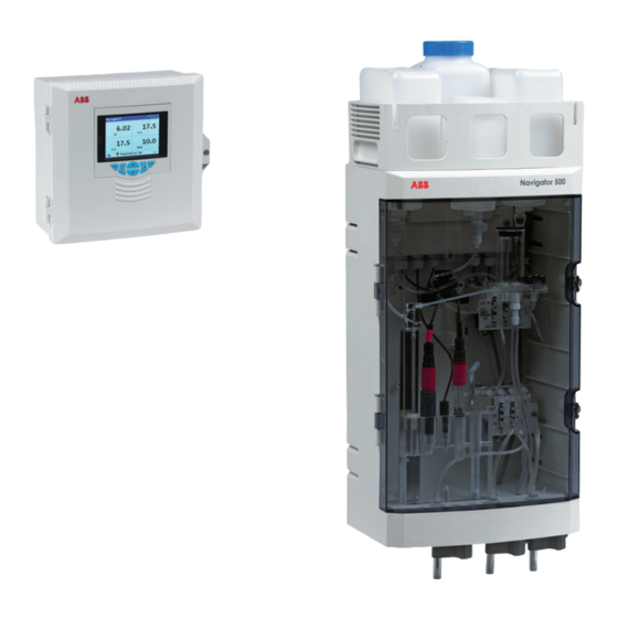
Navigator 500
Sodium analyzer
Introduction
—
Navigator 500
sodium analyzer
The Navigator 500 sodium analyzer is designed to
provide continuous monitoring and control of power
station boiler feed water / steam condensate.
The analyzer comprises a Navigator 540 transmitter
with multiple wet-section capability for up to 4 wet-
sections.
This Operating Instruction provides installation,
operation and maintenance procedures for the
Navigator 550 sodium wet-section and a Navigator
540 transmitter.
Measurement made easy
Advertisement
Table of Contents

Related Manuals for ABB Navigator 500 Series


Summary of Contents for ABB Navigator 500 Series
- Page 1 — A B B M E A S U R E M E N T & A N A LY T I C S | O P E R AT I N G I N S T R U C T I O N | O I/A S O 5 5 0 - E N R E V. G Navigator 500 Sodium analyzer Measurement made easy...
- Page 2 For more information Further publications for the Navigator 500 sodium analyzer are available for free download from: www.abb.com/measurement or by scanning this code: Search for or click on Commisioning Instruction Navigator 550 CI/ASO550-EN Sodium wet-section Commisioning Instruction Navigator 540 CI/AWT540-EN...
-
Page 3: Table Of Contents
Navigator 500 Sodium analyzer Contents Contents 1 Health & Safety ..............3 5 Calibration ..............21 Safety precautions ........... 3 Accessing the Configuration level menus ....21 Potential safety hazards ........... 3 Performing a calibration for the first time – 1.2.1 Navigator 550 sodium wet-section –... - Page 4 Navigator 500 Sodium analyzer Contents 8 Maintenance ..............59 Appendix A – Troubleshooting ......... 72 Chemical solutions ..........59 Diagnostic messages ..........72 8.1.1 Reagent solutions ........59 Calibration pass and fail limits ........ 75 8.1.2 Standard solutions ........59 Checking the temperature input ......76 8.1.3 Salt bridge solution ........59 Incorrect or erratic flow rate readings .....
-
Page 5: Health & Safety
Navigator 500 Sodium analyzer 1 Health & Safety 1 Health & Safety 1.1 Safety precautions Be sure to read, understand and follow the instructions contained within this manual before and during use of the equipment. Failure to do so could result in bodily harm or damage to the equipment. Warning. -
Page 6: Safety Conventions
Navigator 500 Sodium analyzer 1 Health & Safety 1.4 Safety conventions Warning. In this manual, a warning is used to indicate a condition which, if not met, could cause serious personal injury and / or death. Do not proceed beyond a warning until all conditions have been met. Caution. -
Page 7: Navigator 540 Transmitter
ABB is committed to ensuring that the risk of any environmental damage or pollution caused by any of its products is minimized as far as possible. -
Page 8: Overview
2.1 Navigator 550 sodium wet-section The Navigator 550 sodium wet-section has been designed for use with an ABB Navigator 540 transmitter to provide continuous monitoring and control of power station boiler feed water / steam condensate. Sampling points include mixed bed outlets in water treatment plants, extraction pump discharge, boiler feed, boiler drum and steam. -
Page 9: Navigator 540 Transmitter
The Navigator 540 transmitter is designed for continuous monitoring and control of power station boiler feed water / steam condensate and must be used in conjunction with an associated ABB wet-section to measure levels of low level dissolved oxygen / sodium / hydrazine. -
Page 10: Installation
Navigator 500 Sodium analyzer 3 Installation 3 Installation 3.1 Installing the wet-section 3.1.1 Sample requirements 3.1.2 Location Ensure the sampling point is as close as possible to the For general location requirements refer to Fig. 3.1. Install in a wet-section and provides a thoroughly-mixed representative clean, dry, well ventilated and vibration-free location giving easy sample. -
Page 11: Mounting The Wet-Section
Navigator 500 Sodium analyzer 3 Installation 3.1.3 Mounting the wet-section Refer to Fig. 3.2 for wet-section dimensions. The wet-section weighs 4.5 kg (10 lb) – excluding bottle carrier and solutions. Note. Clearance – the enclosure doors can open 180°. If mounting in a confined area, allow sufficient clearance for door opening. -
Page 12: Connecting The External Sample Lines
Navigator 500 Sodium analyzer 3 Installation 3.1.4 Connecting the external sample lines Note. Sample inlet tubing to the base of the wet-section is customer-supplied. Sample inlet tubing must have sufficient wall thickness to withstand the highest sample pressure. Keep tubing lengths short. -
Page 13: Connecting The Reagent / Calibration / Regeneration Tubing
Navigator 500 Sodium analyzer 3 Installation 3.1.5 Connecting the reagent / calibration / regeneration tubing The following tubing connections must be made on site, all other tubing connections are factory-made. All other internal wet-section tubing connections are factory-made. Referring to Fig. 3.5: 1. -
Page 14: Installing The Transmitter
Navigator 500 Sodium analyzer 3 Installation 3.2 Installing the transmitter 3.2.1 Transmitter optional accessories 3.2.3 Panel mounting Optional accessories comprise: Dimensions in mm (in.) Cable gland kit 3.2.2 Transmitter location For transmitter general location requirements refer to Fig. 3.6. (3.6) (1.4) Install in a clean, dry, well ventilated and vibration-free location providing easy access. -
Page 15: Pipe Mounting
Navigator 500 Sodium analyzer 3 Installation 3.2.4 Pipe mounting 3.2.5 Wall mounting Dimensions in mm (in.) Dimensions in mm (in.) 213 (8.38) 214 (8.42) 200 (7.87) fixing centers (7.64) (2.44) Ø6.4 (2.40) (0.25) Cable gland kit Cable gland kit – optional –... -
Page 16: Electrical Connections - Wet-Section
Navigator 500 Sodium analyzer 3 Installation 3.4 Electrical connections – wet-section 3.4.1 Solution ground A stud terminal is located on the left hand side of the flow cell, see Fig. 2.1, page 6. This stud is provided so that the solution can be grounded to ensure there is not a build up of static charge. -
Page 17: Wet-Section Pcb Connections
Navigator 500 Sodium analyzer 3 Installation 3.4.3 Wet-section PCB connections Cable Color Terminal ID Description Note. Calibration valve Refer to Section 3.5.2, page 18, for connection details Green Cal valve 1 +ve at the transmitter. Brown Cal valve 1 –ve Cal valve 2 +ve ... -
Page 18: Electrical Connections - Transmitter
Navigator 500 Sodium analyzer 3 Installation 3.5 Electrical connections – transmitter Warning. If the transmitter is used in a manner not specified by the Company, the protection provided by the equipment may be impaired. Remove all power from supply, relay, any powered control circuits and high common mode voltages before accessing or making any connections. -
Page 19: Accessing The Transmitter Connection Board
Navigator 500 Sodium analyzer 3 Installation 3.5.1 Accessing the transmitter connection board Note. Electrical connections to the wet-section connection board are identified in the Section 3.4.3, page 15. Before fitting cable glands, identify the connections required and cable gland entries to be used. Referring to Fig. -
Page 20: Transmitter Connections
Navigator 500 Sodium analyzer 3 Installation 3.5.2 Transmitter connections I/O module 1 RS485 SMART SENSOR INTERFACE MODULE ANALOGUE OUTPUT BOARD (shown fitted) CM40/0215 ISS.1 CM40/0235 RELAY RELAY OUT 3 OUT 4 Optional I/O module 3 option card communications module I/O MODULE 2 I/O MODULE 3 I/O MODULE 3 (shown fitted) -
Page 21: Setup
Navigator 500 Sodium analyzer 4 Setup 4 Setup This section describes how to set the analyzer up for first-time 7. Remove the supplied O-ring (temporarily secured to use. the top of the right-hand chamber) and fit it over the reference electrode body. If multiple wet-sections are to be connected to a transmitter, an additional setup procedure is required –... -
Page 22: Fitting And Filling The Reservoir (Option)
Navigator 500 Sodium analyzer 4 Setup 4.1.2 Fitting and filling the reservoir (option) 4.1.3 Sensor panel 1. Fill the reagent solution container with appropriate solution. Note. The reservoir is supplied partially-assembled. Assemble only immediately before using the wet-section (to 2. Open the shut-off valve upstream of the wet-section panel avoid the possibility of solution drying out if the wet-section and adjust it until sample is overflowing from the overflow is stored for any length of time). -
Page 23: Calibration
Navigator 500 Sodium analyzer 5 Calibration 5 Calibration This section describes how to calibrate the analyzer once it is 5.1 Accessing the Configuration level menus operational. Calibrations are initiated via the Cal prompt The configuration level menus are used to configure the displayed on Operator pages, or via the Calibration Level and wet-section(s) and set parameter values –... -
Page 24: Performing A Calibration For The First Time - Single-Stream Wet-Section
Navigator 500 Sodium analyzer 5 Calibration 5.2 Performing a calibration for the first time – single-stream wet-section To perform a quick two-point calibration from an Operator page: 1. Press the key (below the Cal prompt). 4. Press the key (below the Yes prompt on the Start Calibration page). -
Page 25: Performing A Calibration For The First Time - Multi-Stream Wet-Section
Navigator 500 Sodium analyzer 5 Calibration 5.3 Performing a calibration for the first time – 4. Press the key (below the Yes prompt on the Sodium multi-stream wet-section Three Stream / Start Calibration page). To perform a quick calibration from an Operator page: The Calibration page is displayed with a bar graph to 1. -
Page 26: Calibration Parameters - Offset And Slope
Navigator 500 Sodium analyzer 5 Calibration 5.4 Calibration parameters – offset and slope 5.5.2 Monitoring calibration progress If the Calibration page is exited by press the key (below the A mV offset is calculated after a single-point or a two-point OK prompt) before the calibration has completed, progress can calibration. -
Page 27: Process Calibration Procedure
Navigator 500 Sodium analyzer 5 Calibration 5.5.4 Process calibration procedure The process calibration procedure can be used to make minor 3. Press the key to select the Enter Configuration menu adjustments to the concentration value. When a process and press the key (below the icon). - Page 28 Navigator 500 Sodium analyzer 5 Calibration 7. Press the key (below the Select prompt). At the transmitter: The Sensor 1 (4) / Sensor Three Stream page (dependent 11. Press the key (below the Yes prompt). on single-stream / multi-stream configuration) is displayed The Process Calibration / Sample Collection page is with the Sensor Calibration menu selected: displayed:...
- Page 29 Navigator 500 Sodium analyzer 5 Calibration 14. Press the key (below the Continue prompt). When the calculation is finished, a new page showing the new reading and process calibration offset values is The next Process Calibration page displayed shows an displayed average of the reading obtained: Process Calibration...
-
Page 30: Grab Sample
Navigator 500 Sodium analyzer 5 Calibration 5.5.5 Grab sample 5.7 Regeneration procedure Pour the sample to be measured into the High Calibration bottle If the sodium electrode is exposed to low concentrations (less (it is advisable to rinse the bottle with the sample to remove the than 1 ppb) for prolonged periods of time, sodium ions are residuals of the calibration solution). -
Page 31: Operation Overview - Transmitter
Navigator 500 Sodium analyzer 6 Operation overview – transmitter 6 Operation overview – transmitter 6.1 Front panel keys The transmitter is operated using the keys on the front panel. These enable local navigation and selection of software options on all displays, acknowledgement and data logging and monitoring. -
Page 32: Transmitter Operation Modes
Navigator 500 Sodium analyzer 6 Operation overview – transmitter 6.2 Transmitter operation modes The transmitter has 4 modes of operation – all modes are accessed from the Operator menu – see Fig. 6.2. Operating – used to display real-time wet-section values on Operating Pages – refer to Section 6.5, page 31. ... -
Page 33: Navigation Overview
Navigator 500 Sodium analyzer 6 Operation overview – transmitter 6.4 Navigation overview Operator Operator Operator Operator Operator Page 1 Page 3 Page 4 Page 5 Page 2 Diagnostics Signals Chart Alarms Outputs View View View View View Calibration Alarm Audit Diagnostic Fig. - Page 34 Navigator 500 Sodium analyzer 6 Operation overview – transmitter Fig. 6.5 shows an overview of Operator Pages 2 to 5. Each Operator Page displays the process value (PV) and temperature from a single wet-section. Fixed, color-coded, user-assignable tags (one for each connected wet-section) and color-coded bargraphs aid identification of each wet-section.
-
Page 35: View Mode
Navigator 500 Sodium analyzer 6 Operation overview – transmitter 6.6 View mode Pages displayed in View mode comprise: Diagnostics View – displays a list of diagnostic messages identified by priority and message – see Fig. 6.6 Alarms View – displays a list a list of alarms identified by priority (sequence number), source and status – see Fig. 6.7 ... -
Page 36: Log Mode
Navigator 500 Sodium analyzer 6 Operation overview – transmitter Signal value / efficiency indicator Units Signals View 2012–04–15 10 : 31: 27 Sensor 1 Value Units Signal type 8.25 Concentration Temperature °C Sensor Output Flow Rate ml/min. Efficiency Last Efficiency Scroll for additional signals Fig. -
Page 37: Calibration Log Entries
Navigator 500 Sodium analyzer 6 Operation overview – transmitter 6.7.1 Calibration log entries Possible calibration log entries along with a description are shown in Table 6.2. The possible Audit Log entries along with a description are shown in Table 6.3. The Diagnostic Log shows the history of diagnostic messages that have been displayed in the Diagnostic View –... -
Page 38: Logging
When handling the SD card / USB stick take care not to touch any exposed metal Note. ABB's DataManager software can be used to store contacts. and view data archived from the transmitter. -
Page 39: Sd Card / Usb Stick Insertion And Removal
Alternatively, you can carry out detailed graphical analysis of the Note. Data stored in the internal memory buffer can still be data on a PC using ABB’s DataManager data analysis software. transferred to the SD card / USB stick when the archive... -
Page 40: Log Files
Navigator 500 Sodium analyzer 6 Operation overview – transmitter 6.8.5 Log files The Alarm Event, Calibration, Diagnostic and Audit logs are archived into the same file. The filenames are formatted as follows: Event logs: <ddmmyy><hhmmss><instrument tag>.AOO 6.8.6 Daylight saving Files containing data generated during the daylight saving period have '~DS' appended to the filename. -
Page 41: Password Security And Access Level
Navigator 500 Sodium analyzer 6 Operation overview – transmitter 6.9 Password security and Access Level Passwords are entered at the Enter Password screen accessed via the Access Level – see Section 6.9.2, below. 6.9.1 Setting passwords Passwords can be set to enable secure access at 2 levels: Calibrate and Advanced. The Service level is password protected at the factory and reserved for factory use only. -
Page 42: Display Icons
Navigator 500 Sodium analyzer 6 Operation overview – transmitter 6.10 Display icons 6.10.1 Diagnostic icons 6.10.2 Title bar icons Log mode – indicates that one of the View pages Note. is currently displayed (Calibration, Alarm, Audit or When a diagnostic condition is detected the Diagnostic) associated NAMUR icon plus the highest priority View mode –... -
Page 43: Log Icons
Navigator 500 Sodium analyzer 6 Operation overview – transmitter 6.10.3 Log icons 6.10.4 Status bar icons Source: wet-section 1 (red) Operator menu – displays the Operator menu S1 = sensor for wet-section 1 when the key is pressed. T1 = temperature for wet-section 1 Autoscroll –... -
Page 44: Menu Descriptions
Tag 1 – 4 Source 1 – 4 Note. Service level menus (not shown) are Invert 1 – 4 password-protected at the factory and intended for use by authorised ABB service technicians only. Fig. 7.1 Overview of sodium menus OI/ASO550–EN Rev. G... -
Page 45: Calibrate
Navigator 500 Sodium analyzer 7 Menu descriptions 7.1.1 Calibrate Used to calibrate the wet-section, regenerate the wet-section, set up calibration parameters, Menu process calibrations and initiate Grab Sample routines. Calibrate Access to the Calibrate menu is permitted via the Calibrate and Advanced levels only. Select Exit Menu... - Page 46 Navigator 500 Sodium analyzer 7 Menu descriptions Menu Comment Defaults Process Calibration Performs a process calibration. This calibration can be used to adjust the concentration value on the wet-section to a value that has been determined in the laboratory. It should only be used to make minor adjustments to the reading.
- Page 47 Navigator 500 Sodium analyzer 7 Menu descriptions Menu Comment Defaults Calibration Setup Low Std Solution Sets the low standard calibration solution value between 50 and 100 ppb 10,000 ppb. High Std Solution Sets the high standard calibration solution value between 50 and 1000 ppb 10,000 ppb.
-
Page 48: Sensor Setup
Navigator 500 Sodium analyzer 7 Menu descriptions 7.1.2 Sensor Setup Used to set the wet-section tag, measurement units, operational and stream ranges and filter type Menu and enable / disable the Flow Meter (optional) and Manual Valve Control functions. Sensor Setup Select Exit Menu... - Page 49 Navigator 500 Sodium analyzer 7 Menu descriptions Menu Comment Defaults Solution Detection Enables / disables the solution detection function. Flow Meter Note. Single-stream wet-sections only. Enables / disables flow measurement. Disabled Flow Meter 1 – 3 Note. Multi-stream wet-sections only. Enables / disables flow measurement for the selected stream.
-
Page 50: Device Setup
Navigator 500 Sodium analyzer 7 Menu descriptions 7.1.3 Device Setup This level is used to access standard setup parameters. Menu Device Setup Select Exit Menu Comment Default Initial Setup Instrument Tag A 16-character alphanumeric device (transmitter) identification tag Navigator displayed in the title bar on all Operator pages. Temperature Units Selects the temperature units displayed (°C or °F). - Page 51 Navigator 500 Sodium analyzer 7 Menu descriptions …Range Change Setup Analog output operation Analogue output 2 is used for the range changing functionality and is scaled depending on the range selected. The mA range is set automatically to 4 to 20 mA. Analog output 2 Range Zero...
-
Page 52: Display
Navigator 500 Sodium analyzer 7 Menu descriptions 7.1.4 Display Used to select the display language, setup Operator page templates (1 to 5), enable diagnostic, Menu view and log functions, set the device’s display brightness / contrast and set the time and date. Display Select Exit... - Page 53 Navigator 500 Sodium analyzer 7 Menu descriptions …Menu Comment Default Settings Sets the following display parameters. Brightness Increases / decreases the device’s brightness settings to suit local environmental conditions. Contrast Increases / decreases the device’s contrast settings to suit local environmental conditions.
-
Page 54: Input/Output
Navigator 500 Sodium analyzer 7 Menu descriptions 7.1.5 Input/Output Input/Output level enables configuration of analog outputs, digital inputs and outputs and relays. Menu Input/Output Select Exit Menu Comment Default Analog Outputs The analog outputs can be configured to retransmit the process variable and temperature values and have a configurable range from 0 to 22 mA. - Page 55 Navigator 500 Sodium analyzer 7 Menu descriptions …Menu Comment Default Digital I/O See page 18 for digital I/O connections. Digital I/O 1 to 6 Sets the polarity of the input or output signal Type Sets the Digital I/O to operate as an output or an input: Off –...
-
Page 56: Process Alarm
Navigator 500 Sodium analyzer 7 Menu descriptions 7.1.6 Process Alarm Used to configure up to 8 independent process alarms. Menu Process Alarm Select Exit Menu Comment Default Alarm 1 to 8 Source Selects the analog value for the process alarm source. None Type Selects the alarm type from:... -
Page 57: Media Card
Navigator 500 Sodium analyzer 7 Menu descriptions 7.1.7 Media Card Used to set the card on / off status, select the process data to be logged, enter file configuration Menu selection and save details and to format the media card. Media Card Media Card level menus are enabled only if an optional media card module is fitted. -
Page 58: Communication
Navigator 500 Sodium analyzer 7 Menu descriptions 7.1.8 Communication Communication level menus are enabled only if an optional communications module is fitted. Menu Communication Ethernet and Email menus enabled only if a Ethernet communications module is fitted. Select Exit Menu Comment Default Profibus... -
Page 59: Device Info
Navigator 500 Sodium analyzer 7 Menu descriptions 7.1.9 Device Info Displays read-only factory-set details for the transmitter and connected wet-section(s). Menu Device Info Select Exit Menu Comment Default Transmitter Serial Number The transmitter’s serial number. Date of Manufacture The transmitter’s date of manufacture. Hardware Revision The transmitter’s hardware version number. -
Page 60: Analog Sources And Digital Input / Output Sources
Navigator 500 Sodium analyzer 7 Menu descriptions 7.2 Analog sources and digital input / output sources 7.2.1 Analog sources Source name* Description Low Level D. O. 1 (4) Hydrazine 1 (4) Measured concentration value for the associated wet-section. Sodium 1 (4) Sodium Stream 1 Measured concentration value for stream 1. -
Page 61: Maintenance
Navigator 500 Sodium analyzer 8 Maintenance 8 Maintenance 8.1 Chemical solutions 8.1.2 Standard solutions The following instructions refer to the preparation of 100 µg l The reagents and calibration solutions detailed in this section and 1 mg l sodium, STANDARD SOLUTION 1 (LOW) and 2 are required to keep the wet-section operating. -
Page 62: Scheduled Servicing
63 (0.4 in.) – refer to Section 4.1.2, page 20, for filling instructions. Note. For information about the regeneration Referring to Fig. 8.1: solution, contact the local ABB representative. – for versions a reservoir, ensure the level of without... -
Page 63: 12-Monthly
Navigator 500 Sodium analyzer 8 Maintenance 8.2.3 12-Monthly 8.3 Automatic regeneration 1. Check the condition of all plastic tubing; replace it as required – refer to Section 8.6, page 65 for multi-stream The regeneration valve is energized for 1 minute. The analyzer wet-sections or Section 8.7, page 67 for single-stream then starts a 2-hour regeneration recovery period. - Page 64 Navigator 500 Sodium analyzer 8 Maintenance 4. If the Calibrate page is not displayed, use the 7. Press the key (below the Select prompt). keys to scroll to the Calibrate page: The Sensor Calibration page is displayed: Menu Sensor Calibration Calibrate Low Calibration High Calibration...
-
Page 65: Manual Regeneration
Navigator 500 Sodium analyzer 8 Maintenance 8.4 Manual regeneration 8.5 Shut-down procedures Referring to Fig. 8.3: Warning. Observe relevant safety procedures when 1. Carefully unscrew plastic sleeve a few turns (with handling reagent solutions. sodium electrode in place). 2. Withdraw sodium electrode from the sleeve and 1. -
Page 66: Preparing The Sodium And Reference Electrodes For Storage
Navigator 500 Sodium analyzer 8 Maintenance 8.5.1 Preparing the sodium and reference electrodes for storage Referring to Fig. 8.4: 1. Unscrew (but do not remove) plastic sleeve carefully slide sodium electrode out of the flowcell 2. Fill the rubber teat (supplied with the sodium electrode) with High Cal solution or typically with 1 mg kg sodium containing a few drops of concentrated ammonia... -
Page 67: Replacing Plastic Tubing - Multi-Stream Wet-Sections
Navigator 500 Sodium analyzer 8 Maintenance 8.6 Replacing plastic tubing – multi-stream wet-sections It is recommended that all plastic tubing is replaced every 12 months. Use only the correct size and type of tubing – refer to Fig. 8.5 and Fig. 8.6 (page 66) for tubing location and Table 8.1, page 66 for tubing lengths. Two sections of tubing are critical: ... - Page 68 Navigator 500 Sodium analyzer 8 Maintenance *For inlet tube routing on wet-sections , refer to Fig. 8.5, page 65, item without flowmeters Fig. 8.6 Physical arrangement, inlet tubing only – sodium multi-stream wet-section flowmeters with Length Part number Item Description Quantity mm (in.) and size...
-
Page 69: Replacing Plastic Tubing - Single-Stream Wet-Sections
Navigator 500 Sodium analyzer 8 Maintenance 8.7 Replacing plastic tubing – single-stream wet-sections It is recommended that all plastic tubing is replaced every 12 months. Use only the correct size and type of tubing – refer to Fig. 8.7 for tubing location and Table 8.2, page 68 for tubing lengths. Two sections of tubing are critical: ... - Page 70 Navigator 500 Sodium analyzer 8 Maintenance Item Description Length mm (in.) Part number Quantity 0212397 Reagent tubing 550 (21.6) in. ID x in. OD Calibration solution 2 tubing (disconnect QD coupling first) 250 (10) 0212214* Regeneration solution tubing (if fitted) – disconnect QD coupling first 250 (10) in.
-
Page 71: Specification - Analyzer
Navigator 500 Sodium analyzer 9 Specification – analyzer 9 Specification – analyzer Operation Environmental data Measuring range Ambient operating temperature: 0.01 to 10,000 ppb 0 to 55 ºC (32 to 131 ºF) Units of measure Ambient operating humidity: ppb, µg/l, µg/kg Up to 95 % RH non-condensing Accuracy Storage temperature:... -
Page 72: Specification - Transmitter
Navigator 500 Sodium analyzer 10 Specification – transmitter 10 Specification – transmitter Operation Relay outputs Display 4 standard 89 mm (3.5 in) color 1/4 VGA TFT, liquid crystal display (LCD) with 2 optional built-in backlight and brightness / contrast adjustment Fully-programmable. -
Page 73: Specification - Wet-Section
Navigator 500 Sodium analyzer 11 Specification – wet-section 11 Specification – wet-section Mechanical data Protection IP54 Dimensions Height – 668 mm (26.30 in), including solution bottles Width – 290 mm (11.41 in) – door shut Depth – 185 mm (7.28 in) door closed – minimum (excluding fixing brackets) Weight –... -
Page 74: Appendix A - Troubleshooting
Navigator 500 Sodium analyzer Appendix A – Troubleshooting Appendix A – Troubleshooting A.1 Diagnostic messages The transmitter is programmed to display diagnostic messages Diagnostic Icon NAMUR Status to provide information on servicing requirements and any other conditions that develop during operation. Failure All diagnostic messages displayed on the transmitter are added to the transmitter's Audit Log. - Page 75 Navigator 500 Sodium analyzer Appendix A – Troubleshooting Icon Diagnostic message Possible cause and suggested action NV error – software key 1 (CRC Comms.) Failure of non-volatile memory on software key 1 board or permanent corruption of its data. NV Error SW Key 1 Cycle power to the device.
- Page 76 Navigator 500 Sodium analyzer Appendix A – Troubleshooting Icon Diagnostic message Possible cause and suggested action Memory card is more than 90% full. Media Near Full Replace memory card. Out of low calibration solution. No Low Cal Replace low calibration solution and start a calibration. (S1, S2, S3, S4) .
-
Page 77: Calibration Pass And Fail Limits
Navigator 500 Sodium analyzer Appendix A – Troubleshooting A.2 Calibration pass and fail limits After a two point calibration, the percentage Slope is calculated. Percent slope Action The calibration pass limits and their meanings are shown in Table A.2. Slope > 110 % Calibration unacceptable. -
Page 78: Checking The Temperature Input
Navigator 500 Sodium analyzer Appendix A – Troubleshooting A.3 Checking the temperature input A.4 Incorrect or erratic flow rate readings 1. Check that the wet-section responds to a temperature Incorrect or erratic flow rate readings may be due to a blockage input. -
Page 79: Appendix B - Multi-Stream Sodium Wet-Section
Navigator 500 Sodium analyzer Appendix B – Multi-stream sodium wet-section Appendix B – Multi-stream sodium wet-section The sample streams enter the bottom of the wet-section (via flow meters if fitted), diverting sample to the sample valve manifold (mounted on the top of the bracket) and the calibration valve manifold to the constant-head unit. The solenoid valves are used to switch between sample streams. -
Page 80: Appendix C - Multiple Wet-Section Setup
Navigator 500 Sodium analyzer Appendix C – Multiple wet-section setup Appendix C – Multiple wet-section setup A single Navigator 540 transmitter can monitor up to 4 wet-sections. The wet-sections can be any combination of the three Navigator 500 parameters – sodium, low level dissolved oxygen and hydrazine. Note that the transmitter cannot monitor more than 1 wet- section if the wet-section is a multi-stream sodium. -
Page 81: Appendix D - Spare Parts And Consumables
Navigator 500 Sodium analyzer Appendix D – Spare parts and consumables Appendix D – Spare parts and consumables D.1 Navigator 500 sodium consumables D.2 Navigator 500 sodium wet-section spares Part No. / Type Usage / Volume Part No. Description AWRS5000101 General purpose sodium measurements AW500 040 Flowmeter upgrade kit... - Page 82 Navigator 500 Sodium analyzer Appendix D – Spare parts and consumables Part No. Description Part No. Description 1048880 Sodium electrode cable assembly AW501 053 Solenoid valve – Multi-stream Cal / Stream switch Port configuration W.R.T electrical connector N / O I N / O U N / C AW501 037...
- Page 83 Navigator 500 Sodium analyzer Appendix D – Spare parts and consumables Part No. Description Part No. Description AW501 057 Sodium electrode sleeve and O-ring AW501 062 Pressure switch assembly (2 in.set point) including O-ring and fasteners AW501 058 Pt1000 assembly (sodium) plus O-ring AW501 063 Solenoid valve mounting plate, calibration and stream switching...
- Page 84 Navigator 500 Sodium analyzer Appendix D – Spare parts and consumables Part No. Description Part No. Description AW501 066 Entrainment tube and connecting tubing AW501 070 Calibration solution bottle kit assembly – includes hazard labels: Calibration Solution 1 and Calibration Solution 2 AW501 067 Entrainment tube centralizing collar AW501 071...
- Page 85 Navigator 500 Sodium analyzer Appendix D – Spare parts and consumables Part No. Description AW501 080 Cable assembly – single-stream sodium solenoid valve AW501 081 Cable assembly – multi-stream sodium solenoid valve AW501 082 Cable assembly – calibration and reagent solenoid valve AW501 085 Cable assembly –...
-
Page 86: Navigator 540 Transmitter
Navigator 500 Sodium analyzer Appendix D – Spare parts and consumables D.3 Navigator 540 transmitter Part No. Description Part No. Description AW500 050 AWT processor board spares kit AW500 054 AWT SD media PCB spares kit AW500 055 AWT USB media PCB spares kit AW500 051 AWT main board spares kit AW500 056... - Page 87 Acknowledgements Microsoft, Windows and Excel are registered trademarks of Microsoft Corporation in the United States and/or other countries. Modbus is a registered trademark of the Modbus-IDA organization. Sales Service Software...
- Page 88 We reserve the right to make technical changes or modify the contents of this document without prior notice. With regard to purchase orders, the agreed particulars shall prevail. ABB does not accept any responsibility whatsoever for potential errors or possible lack of information in this document.
Need help?
Do you have a question about the Navigator 500 Series and is the answer not in the manual?
Questions and answers