Table of Contents
Advertisement
Quick Links
Advertisement
Table of Contents
Troubleshooting

Related Manuals for ABB TOTALFLOW PGC1000


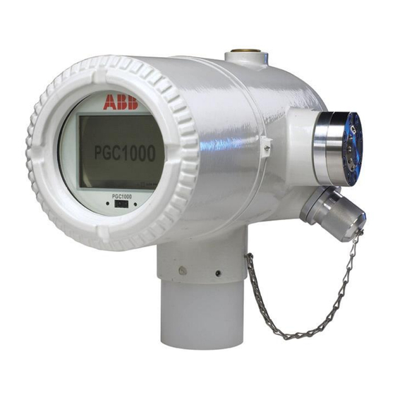
Summary of Contents for ABB TOTALFLOW PGC1000
- Page 1 2103406 Rev. AE PGC1000 Chromatograph User’s Manual...
- Page 2 Intellectual Property & Copyright Notice ©2018 by ABB Inc., Totalflow (“Owner”), Bartlesville, Oklahoma 74006, U.S.A. All rights reserved. Any and all derivatives of, including translations thereof, shall remain the sole property of the Owner, regardless of any circumstances. The original US English version of this manual shall be deemed the only valid version. Translated versions, in any other language, shall be maintained as accurately as possible.
-
Page 3: Table Of Contents
TABLE OF CONTENTS INTRODUCTION ....................XV Chapter Descriptions ....................xv Getting Help......................xv Before Calling ......................xv Key Symbols ......................xvi Safety Practices and Precautions ................xvi Safety Guidelines ....................... xvi Safety First......................... xvii Equipment Markings ....................xvii Grounding the Product ....................xvii Operating Voltage ...................... - Page 4 1.7.10 Tube Preparation ..................1–24 Calculating Lag Time ................1–24 1.8.1 Calculations ....................1–25 1.8.2 Calculating Using Actual Pressure............. 1–25 PGC1000 Standard Software Features ............ 1–26 1.9.1 Audit Quality Data ..................1–26 1.9.2 Security System ..................1–26 1.9.3 Engineering Units ..................1–27 1.9.4 Supported Protocols ..................
- Page 5 2.2.1 Shipping Carton ................... 2–4 2.2.2 Unpacking ....................2–5 2.2.3 Bill of Lading ....................2–5 2.2.4 Inspection ....................2–5 2.2.5 Damaged Components................2–5 Sample Probe Installation ................2–5 2.3.1 Materials ...................... 2–6 2.3.2 Instructions ....................2–6 Stand-Alone Installation ................2–7 2.4.1 Materials Not Supplied ................
- Page 6 2.16.2 Customer Supplied Materials ..............2–29 2.16.3 Instructions ....................2–29 2.17 Carrier/Calibration Bottle Rack Installation on a Process Line ....2–36 2.17.1 Instructions ....................2–36 2.18 ENC82 Carrier Gas Bottle Rack Installation ..........2–36 2.18.1 Materials ..................... 2–37 2.18.2 Instructions ....................2–37 2.19 Carrier Gas Regulator Installation ............
- Page 7 2.31.1 Customer Supplied Materials ..............2–64 2.31.2 Instructions ....................2–65 2.32 110/240 Vac to 12/24 Vdc Power Supply Installation ....... 2–66 2.32.1 Instructions ....................2–68 2.33 Battery Pack Installation ................2–68 2.33.1 Instructions ....................2–69 2.34 Solar Panel Power Pack ................2–72 2.34.1 Instructions ....................
- Page 8 4.7.2 Cold Start Instructions ................4–10 Restore Factory Defaults ................. 4–11 4.8.1 Instructions ....................4–11 Lithium Battery Status ................4–12 4.9.1 Instructions ....................4–12 4.10 Changing the PGC1000 Clock ..............4–12 4.10.1 Clock Change Not Crossing a Log Period Boundary......... 4–13 4.10.2 Forward Clock Change Crossing a Log Period Boundary ......
- Page 9 Troubleshooting Alarms ................5–7 5.3.1 Operators ..................... 5–8 5.3.2 Alarm Severity ..................... 5–8 5.3.3 Pressure Regulator Alarm ................5–8 5.3.4 Sample Pressure Alarm................5–10 5.3.5 Oven Temperature Error Alarm ..............5–11 5.3.6 No Stream Valve Selected Alarm .............. 5–11 5.3.7 Digital-Analog Board Communication Error Alarm ........
- Page 10 5.6.8 RS-485 Communication Test ..............5–37 SPECIAL APPLICATIONS ................. 6–1 Introduction ....................6–1 6.1.1 Using the Special Applications Section ............6–2 General Manual Peak Find Procedure ............6–3 6.2.1 Purpose ......................6–3 6.2.2 PCCU32 and the User-Interface ..............6–3 Before Starting – Save and Restore ............6–5 6.2.3 6.2.4 General Setup Checklist (Per PGC1000 Start-Up Guide) ......
- Page 11 Table of Figures Figure 1-1 Typical Single Stream Installation ..................1–2 Figure 1-2 Typical Multi-Stream Installation ..................1–3 Figure 1-3 Modular Design PGC1000 ....................1–6 Figure 1-4 PGC1000 Enclosure ......................1–7 Figure 1-5 PGC1000 Enclosure Left Side ..................1–8 Figure 1-6 PGC1000 Enclosure Right Side ..................1–8 Figure 1-7 PGC1000 Enclosure Bottom View ..................
- Page 12 Figure 2-11 ENC82L–Adjustment Assembly ..................2–13 Figure 2-12 ENC82L–Pipe Mount installation ................... 2–14 Figure 2-13 ENC82L–Chain Retainer Lock ..................2–14 Figure 2-14 ENC82L–Optional Support Leg Overview ..............2–15 Figure 2-15 ENC82S–Channel Tubing Installation ................2–16 Figure 2-16 ENC82S–Pipe-Mount Split Brackets ................2–17 Figure 2-17 ENC82S–...
- Page 13 Figure 2-55 ENC82L Electric Heater Installed in Enclosure ............2–54 Figure 2-56 ENC82S Electric Heater Installed in Enclosure ............2–54 Figure 2-57 ENC82L Electric Heater Option Wiring Instructions ............. 2–55 Figure 2-58 ENC82S Electric Heater Option Wiring Instructions ............. 2–55 Figure 2-59 6200 Enclosure Pipe-Mounting Installation..............
- Page 14 Figure 6-2 PGC1000 Cold Boot via PCCU32 and the 32-Bit Loader ..........6–6 Figure 6-3 Save and Restore TfCold and TfData ................6–7 Figure 6-4 Manual Peak Find Dialog Screen ..................6–9 Figure 6-5 Parameter Columns ......................6–9 Figure 6-6 Failure to Define a Front Gate ..................6–10 Figure 6-7 A Successful Front Gate Determination ................
- Page 15 List of Tables Table 1–1 Hydrocarbons ........................1–4 Table 1–2 System Specifications ....................... 1–5 Table 1–3 12 Vdc Battery Power Supply System Maximum Cable Lengths ........1–21 Table 1–4 AC Power Supply System Maximum Cable Lengths ............1–21 Table 1–5 Internal Volume of Commonly Used Sample Transport Tubing ........1–23 Table 1–6 Communication Option Comparison ................
- Page 16 Table 7–19 BBK Column - Data for Manual Peak Find ..............7–26 Table 7–20 BBM Column Train Data Sheet (C3 to C6+ w/H2S) ............7–28 Table 7–21 BBM Blend ........................7–30 Table 7–22 BBM Column - Data for Manual Peak Find ..............7–30 Table 7–23 BBR Column Train Data Sheet (H2S in Fuel Gas) ............
-
Page 17: Introduction
Introduction This manual is written to provide an experienced chromatography technician with the requirements necessary to install, set up and operate the Totalflow PGC1000 Process Gas Chromatograph. Each of the chapters in this manual presents information in an organized and concise manner. -
Page 18: Key Symbols
Be prepared to give the customer service representative a detailed description of the problem. Note any alarms or messages as they appear. Prepare a written description of problem. Know the software version, board and optional part numbers. Key Symbols The following symbols are used frequently in the manual. -
Page 19: Safety First
Capacitors in the equipment can still be charged even after the unit has been disconnected from all power supplies. Safety First Various statements in this manual that are identified as conditions or practices that could result in equipment damage, personal injury or loss of life are highlighted using the following icons: Exercise caution while performing this task. -
Page 20: Danger From Loss Of Ground
Compliance EU Directive 2012/19/EU - Waste Electrical and Electronic Equipment (WEEE) ABB Industrial Automation, Measurement and Analytics, is committed to actively protecting the environment. Do not dispose of WEEE as unsorted municipal waste. Collect WEEE separately. Participation in the management of WEEE is critical to the success of WEEE collection. -
Page 21: System Description
C6+, C3, IC4, NC4, neoC5, IC5, NC5 and H Again, the above list is only a sample of the trains available. Contact an ABB Totalflow project engineer to help select the appropriate trains for the application. 2103406 Rev. AE... - Page 22 Figure 1-1 Typical Single Stream Installation 2103406 Rev. AE Page 1–2...
-
Page 23: Figure 1-2 Typical Multi-Stream Installation
Figure 1-2 Typical Multi-Stream Installation 2103406 Rev. AE Page 1–3... -
Page 24: Processing A Sample
1.2 Processing a Sample In the first phase of the cycle, a process gas sample is extracted from the process stream. This sample is then processed for particulate removal and phase integrity by the sample conditioning system (optional). Upon completion, the sample is transported to the PGC1000 and injected in the chromatographic columns where component separation occurs. -
Page 25: Hardware Systems
224.0 mm 397.3 mm 10.8 kg 1.3.1 Standard Hardware Features The ABB Totalflow PGC1000 features a rugged, field-ready design. Installation, start-up and troubleshooting times have been greatly reduced due to these user- friendly hardware features: Enclosure, compact design ... -
Page 26: Recommended Spare Parts
Powder coating Weatherproof construction Modular design (see Figure 1-3) Digital controller assembly Analytical module with compact design and single bolt replacement Feed-through assembly with flame path arrestors Termination panel State-of-the-art electronics 32-bit digital controlling electronics (i.e., no analog control loops) ... -
Page 27: Figure 1-4 Pgc1000 Enclosure
The custom designed, explosion-proof enclosure consists of a cylindrical shaped, cast aluminum housing, powder coated, with front and rear end caps for access to internal components. Figure 1-4 through Figure 1-7 displays the outline dimensions of the PGC1000. The end caps have precision engineered threading and are susceptible to damage if treated roughly. -
Page 28: Figure 1-5 Pgc1000 Enclosure Left Side
Figure 1-5 PGC1000 Enclosure Left Side Figure 1-6 PGC1000 Enclosure Right Side 2103406 Rev. AE Page 1–8... -
Page 29: Feed-Through Assembly
Figure 1-7 PGC1000 Enclosure Bottom View 1.3.4 Feed-Through Assembly Independent process streams are connected to the PGC1000 directly through the feed-through assembly (see Figure 1-8) or through an optionally installed sample conditioning system. The feed-through assembly also serves as the connection for carrier gas and calibration streams and contains the vents for sample and column gases. -
Page 30: Analytical Module
Figure 1-8 PGC1000 Feed-Through Assembly The 0.5 micron filters should NOT be considered a replacement for the primary filtering system. Optional sample conditioning modules are designed for this purpose. 1.3.4.2 Vents Feed-through assembly vents do not have filters but will require vent tubing to be attached and routed accordingly. -
Page 31: Figure 1-9 Analytical Module
Analog to digital conversion circuits Digital oven temperature controller Digital auxiliary heater controller (optional feed-through heater) Dual digital pressure regulators Sample pressure sensor Pressure sensors (100 PSI max.) Thermal conductivity detectors System level voltage monitoring ... -
Page 32: Figure 1-10 Manifold Assembly
Figure 1-10 Manifold Assembly 1.3.5.3 Analytical Processor Assembly The analytical processor provides real-time system control and measurement of the analytical processes within the PGC1000. This is accomplished by interfacing with all of the sensors in the GC module (and optional feed-through temperature sensor) as well as controlling the carrier pressure regulator valves, sample stream valves, the pilot valve and the heaters. -
Page 33: Figure 1-11 Analytical Processor Assembly
Figure 1-11 Analytical Processor Assembly 1.3.5.4 GC Module The GC module is comprised of three components: columns, chromatographic valve and GC module circuit board. The valve controls the flow of gas within the system. The columns perform the separation of the gas into component parts for analysis. -
Page 34: Digital Controller Assembly With Vga Display
1.3.6 Digital Controller Assembly with VGA Display This assembly (see Figure 1-13) contains the digital electronic board, mounting assembly and an optional VGA display. The digital controller board provides control parameters to the analytical processor board and stores and processes the data sent from the analytical processor board. - Page 35 12/19/ 05 16:49:21 USER Alarm Mode Stream Time Normal PGC Menu Analyzer Chrom Control Results Display Analyzer ID : Commands: Streams: Stream Current Abort Alarms BACK Results Hold Stream 2 User Definable Screen Stream 3 Alarm Mode Stream Time Steam 4 Normal Analyzer Control Next Stream...
-
Page 36: Termination Board
1.3.8 Termination Board The PGC1000 termination board acts as a connection to the outside world. It features transient protection, a voltage regulator for the digital controller, positive temperature co-efficient fuses (PTC) and many other safeguards to protect the remainder of the system from electrical damage (see Figure 1-15). All outside communications and I/O are channeled through this board. -
Page 37: Grounding The Pgc1000
SECONDARY COMPONENT SIDE PRIMARY COMPONENT SIDE DIGITAL I/O POWER VOLTAGE REGULATOR SECURITY SWITCH INPUTS OUTPUTS ETHERNET LOCAL SERIAL DATA 5VDC POWER RECEPTICAL CONNECTION SERIAL PORT 2 TERMINATION SERIAL PORT 1 TERMINATION SERIAL PORT 2 SERIAL PORT 1 SECURITY ENABLED D12 D11 USB HOST RECEPTICAL STATUS ANALYTICAL PROCESSOR... -
Page 38: Figure 1-16 Pgc1000 Grounding Considerations
Figure 1-16 PGC1000 Grounding Considerations 2103406 Rev. AE Page 1–18... -
Page 39: Sample Probe
1.5 Calibration/Validation Stream On the PGC1000 feed-through assembly, one or two of the sample streams may be used for a calibration input. ABB Totalflow recommends a metal diaphragm regulator set to 15 2 PSIG input. Specific calibration blends are discussed in detail in this manual’s Application section;... -
Page 40: Operating Voltages And Cable Lengths
Additional devices connected to the PGC1000 and requiring power (XMVs, radios, etc.) must be factored into this calculation. Refer to their technical specifications for the requirements of each or call ABB Totalflow for help computing cable requirements for additional loads. -
Page 41: Table 1-3 12 Vdc Battery Power Supply System Maximum Cable Lengths
Table 1–3 12 Vdc Battery Power Supply System Maximum Cable Lengths (No External Devices Connected to PGC1000, 12 Vdc Battery Power Supply Only) Min. Batt Model/Option Units 12 AWG 14 AWG 16 AWG 6 mm^2 4 mm^2 2.5 mm^2 1.5 mm^2 10AWG Voltage (V) (ft) -
Page 42: Sample Transport Tubing Design
1.7 Sample Transport Tubing Design Information in this section enables the user to design the sample transport tubing connected between the TCR sample probe and the installed PGC1000. Minimizing transport lag time and maintaining a single vapor phase sample are important factors to consider when selecting transport tubing. -
Page 43: Gas Volume In Transit Tubing
Table 1–5 Internal Volume of Commonly Used Sample Transport Tubing Tube Outside Diameter Tube Wall Thickness (in.) Volume per Foot (cc) (in.) 0.02 0.035 0.035 0.035 1.7.5 Gas Volume in Transit Tubing Gases are compressible, and the volume of gas in the transport tubing for standard conditions (atmospheric pressure and 70F [21.1C]) is a function of gas pressure and temperature within the tubing. -
Page 44: Heat Tracing Sample Lines
1.7.8 Heat Tracing Sample Lines If there is a possibility that the vapor sample could condense in the sample transport line, heat tracing the sample line should be considered (see Figure 1-17). To determine the heat tracing temperature, a dew point calculation can be performed based on the worst case sample composition and transport pressure. -
Page 45: Calculations
PGC1000 HEATED CABINET LIQUID DRAIN RM-1 RM-2 RM- 3 ANALYZER 10 cc/ min. HV-3 BYPASS RM-4 RM-5 By- Pass Flow HV-1 HV-2 800 cm/ min Typical HV-4 STREAM 1 STREAM 2 HV-5 115 VAC 60 HZ HEATER HV-8 125 WATT HV-7 LIQUID DRAIN HV-6... -
Page 46: Pgc1000 Standard Software Features
1.9 PGC1000 Standard Software Features ABB Totalflow’s onboard and host software work in concert to provide many key features that enable the user to access, control and share data. The user-friendly interface allows multi-faceted report and communication capabilities without compromising the integrity of the system or data. -
Page 47: Engineering Units
1.10 PCCU Local Communication Options Local communication with the PGC1000 requires the use of PCCU32 software running on a PC and a man machine interface (MMI) cable. ABB Totalflow recommends using a USB cable for high speed local communication in remote locations. -
Page 48: Pgc1000 Start-Up Diagnostics
1.5 Minutes 1.11 PGC1000 Start-Up Diagnostics The ABB Totalflow PGC1000 has an extensive, built-in list of tests which are performed each time the unit is started. This startup. testing may be disabled, but it is recommended that it be left enabled. These diagnostics consist of four areas of testing: ... -
Page 49: Historical Data
During the initial startup, all streams will be disabled. During the stream test, streams with input pressure will be re-enabled, tested and either passed or failed. Streams with no initial input pressure will fail. 1.12 Historical Data The PGC1000 compiles historical data that can be used for custody transfer needs, verifies PGC1000 operation over time and provides a limited data backup for communication link reliability. -
Page 50: Tcr Sample Probe (Optional Equipment)
The length of the sample probe is dependent on the diameter of the user’s process line. ABB Totalflow recommends that a TCR be installed with the PGC1000. Refer to Figure 1-19. Table 1–7 Optional Temperature Compensated Regulator (TCR) -
Page 51: Enc82 Environmental Enclosure (Optional Equipment)
Installation should allow the probe to penetrate the center 1/3 of the stream being processed. This allows sufficient heat transfer with the flowing sample. The sample probe inlet should be high enough to avoid the sampling of any liquids at bottom of the line. ... -
Page 52: Figure 1-20 Enc82L Environmental Enclosure With Electric Heater
BOTTLE RACK OPTION ELECTRIC HEATER OPTION POWER SWITCH THERMOSTAT PWR/COMM OUTLET BOX CALIBRATION INSULATED BLEND ENCLOSURE WALL Figure 1-20 ENC82L Environmental Enclosure with Electric Heater CATALYTIC HEATER OPTION BOTTLE RACK OPTION POWER SWITCH THERMOSTAT PWR/COMM OUTLET BOX CALIBRATION BLEND INSULATED ENCLOSURE WALL Figure 1-21 ENC82L Environmental Enclosure with Catalytic Heater 2103406 Rev. -
Page 53: Figure 1-22 Enc82S Environmental Enclosure With Electric Heater
HEATER KIT: THERMOSTAT VARITHERM 120 VAC, 400 WATT INSULATED ENCLOSURE WALL CALIBRATION BLEND BOTTLE BOTTLE RACK OPTION CYLINDER: M009 FITTINGS: CGA180 Figure 1-22 ENC82S Environmental Enclosure with Electric Heater CATALYTIC HEATER OPTION BOTTLE RACK OPTION CALIBRATION BLEND THERMOSTAT INSULATED ENCLOSURE WALL Figure 1-23 ENC82S Environmental Enclosure with Catalytic Heater 2103406 Rev. -
Page 54: Optional Features
1.14.1.2 Mounting Options The ENC82 may be mounted directly on the pipe run, with or without the sample probe enclosed. Optional support leg(s) are available for added support when mounted on the pipe run. Optionally, a free-standing kit may be used to mount the enclosure next to the process line. -
Page 55: Mounting Brackets
2494-001 Figure 1-24 Available Sample Conditioning Modules Table 1–8 Sample Conditioning Module Descriptions Part Number Description Designed for clean, dry, stable gas with minor amounts of particulate contamination where the sample point is more than 10’ (3m) and less than 50’ (15m) from the PGC1000. The user must guarantee that upset conditions, compressor failure or other problems do 2102023-001 not occur. -
Page 56: Figure 1-25 Single And Multiple Stream Sample Conditioning Assemblies
See Figure 1-26 and Figure 1-27 for installed dimensions. Figure 1-25 Single and Multiple Stream Sample Conditioning Assemblies Figure 1-26 Single Stream Conditioning Module Dimensions 2103406 Rev. AE Page 1–36... -
Page 57: Security Seal (Optional Equipment)
Figure 1-27 Multiple Stream Conditioning Module Dimensions 1.16 Security Seal (Optional Equipment) For some PGC1000 installations, it may be preferred to attach a security seal on the enclosure’s front and rear end caps. To accommodate the seal, please note the holes located in the tab that are on each end cap (See Figure 1-28). 1.16.1 Customer Supplied Materials ... -
Page 58: Instructions
1.16.2 Instructions 1) Insert the security wire through the holes located on the end cap tabs. 2) Bring the ends together. Upon completion, insert through the holes in the security seal (see Figure 1-29). 3) Use the seal press to compress the seal into the wire. Ensure that the wire is firmly captured inside the seal. -
Page 59: 6800 Optional Equipment Enclosure
110/240 Volt to 12 Vdc 110/240 Volt to 24 Vdc Communications kit 1.17.3 6800 Optional Equipment Enclosure The 6800 enclosure can accommodate the following: Communication kit Solar panel power option Two (2) each - 110 AH batteries ... -
Page 60: 115/230 Vac Ups Power Option (24 Vdc Systems Only)
Applicable only on 12 Vdc systems Solar Panel Solar Panel Figure 1-30 6800 Enclosure with 12/24 Vdc Solar Panel Power Pack Option 1.18.2 115/230 Vac UPS Power Option (24 Vdc Systems Only) This option assumes the site availability of 115/230 Vac power. A Uninterruptable Power Supply (UPS) and two 50 AH batteries provide backup power for short power interruptions. -
Page 61: Explosion-Proof Power Supply (Optional Equipment)
Figure 1-31 6800 Enclosure with 115/230 Vac UPS Power Option 1.18.3 Explosion-Proof Power Supply (Optional Equipment) For installations requiring an explosion-proof power supply, ABB Totalflow provides two power supplies (115 Vac and 230 Vac to 12/24 Vdc) that meet these requirements and are housed in explosion-proof enclosures. -
Page 62: Figure 1-32 Explosion Proof Ac Power Supply
Figure 1-32 Explosion Proof AC Power Supply 2103406 Rev. AE Page 1–42... -
Page 63: Installation
INSTALLATION 2.1 Overview This chapter provides information for the field installation of the PGC1000 and optional equipment. After completing the procedures within this chapter, the PGC1000 is ready for start-up. The PGC1000 is designed to be pipe mounted (see Figure 2-1). Optionally, a shelf mounting kit (see Figure 2-2) may be purchased for use in mounting the unit on a wall, inside or outside of a building or on a mounting plate for use in the optional environmental enclosure. -
Page 64: Locating Area For Installation
PGC1000 SAMPLE PROBE CALIBRATION GAS CARRIER GAS Figure 2-1 Basic Meter Run Installation MOUNTING PLATE FLANGE WALL SHELF Figure 2-2 Typical Wall Shelf Mount Installation 2.1.3 Locating Area for Installation The PGC1000 is designed for mounting on large process lines, 2-inch to 12-inch pipe sizes. -
Page 65: Installation
Be certain the installation site is clean and free of foreign debris that could affect PGC1000 operation. The PGC1000 should be located as close as possible to the sample probe installation point. This prevents the need for high gas flow rates through the sample lines to ensure the analysis accuracy of the current sample. -
Page 66: Unpacking And Inspection
Installation Instructions ENC82L Optional Pwr/Comm Outlet Box Assembly 2.16 Carrier/Calibration Bottle Rack Installation on Meter Run 2.17 ENC82 Carrier Gas Bottle Rack Installation 2.18 Carrier Gas Regulator Installation 2.19 ... -
Page 67: Unpacking
2.2.5 Damaged Components If there is any damage or noticeable defects, notify the local ABB Totalflow representative. Keep all shipping materials as evidence of damage for the carrier’s inspection. ABB Totalflow will arrange for immediate repair or replacement. -
Page 68: Materials
2.3.1 Materials ¾” NPT pipe coupling (previously installed) Sample probe (configuration to be determined by the technician and is based on installation and local codes) Teflon ® tape Or customer-supplied pipe dope (suitable for chromatography) 2.3.2 Instructions 1) Shut down the process line, and isolate it from the gas source. -
Page 69: Stand-Alone Installation
One (1) 2” mounting pipe (installed). Length dependent upon the final overall preferred height of the PGC1000. Optional equipment may be ordered from ABB Totalflow. 2.4.2 Instructions 1) Select a location to install the mounting pipe that allows for easy user access and is close to the sample probe. -
Page 70: Materials
If the installation includes a free-standing environmental enclosure, follow these instructions; otherwise, move to the next section. The following steps will typically require two people. 2.5.1 Materials Four (4) each - ½-13 x 1 ¼ SST bolt Four (4) each - ½ SST flat washer ... -
Page 71: Small Free-Standing Environmental Enclosure Installation
57.00" 84.00" 55.50" 4.00" 27.00" 21.50" 34.00" 24.00" 38.00" Figure 2-5 ENC82L–Enclosure Stand Installation Figure 2-6 ENC82L–Enclosure Mounting Hardware 2.6 Small Free-Standing Environmental Enclosure Installation 2103406 Rev. AE Page 2–9... -
Page 72: Materials
If the installation includes a small, free-standing environmental enclosure, follow these instructions; otherwise, move to the next section. 2.6.1 Materials Four (4) each - ½-13 x 1 ¼ SST bolt Four (4) each - ½ SST flat washer ... -
Page 73: Large Pipe-Mounted Environmental Enclosure Mounting Kit
Existing Channel Tubing Spring Nut (4 places) Stand Screw, Lock Washer & Washer (4 places) Figure 2-8 ENC82S–Enclosure Mounting Hardware 4) Move the channel spring nut into position so that the bolt will screw into the nut. Screw the bolt into the nut. Do not tighten. 5) Repeat for all other corners. -
Page 74: Figure 2-9 Enc82L-Mounting Brackets
2.7.2 Instructions 1) Set two pieces of angle iron (see Figure 2-9) on the bottom of the upside down enclosure. Ensure that the side with the holes is facing the bottom of the enclosure and the solid sides of the angle iron are facing each other. Angle iron should be spaced so that the diameter of the pipe will fit in between. -
Page 75: Figure 2-10 Enc82L-Mounting Hardware Installation
(31.00) Figure 2-10 ENC82L–Mounting Hardware Installation TIGHTENING CHAIN LENGTHS -001 13.00" .75 FLAT WASHER .75 SPLIT WASHER -002 19.00" .75 NUT -003 25.00" -004 32.00" MASTERLINK .75 ALL THREAD -005 38.00" Figure 2-11 ENC82L–Adjustment Assembly 12) Wrap the mounting chain underneath the pipe (see Figure 2-12). Feed the chain up through the square retainer hole of the angle iron. -
Page 76: Instructions
(31.00) VIEW B-B VIEW A VIEW B VIEW A-A Figure 2-12 ENC82L–Pipe Mount installation Figure 2-13 ENC82L–Chain Retainer Lock 2.8 Optional Support Leg Kit Installation If the installation includes a pipe-mounted environmental enclosure and requires an optional support leg, follow these instructions;... -
Page 77: Small Pipe-Mounted Environmental Enclosure Mounting Kit
(31.00) 22.75 37.00 Figure 2-14 ENC82L–Optional Support Leg Overview 4) Screw the bolt into the nut, but leave loose for later adjustment. Repeat for the other corner. 5) If installing two support legs, repeat for the other angle iron. Final tightening of the bolts may be performed after the support leg(s) are in the preferred positioned on a flat, stable surface. -
Page 78: Figure 2-15 Enc82S-Channel Tubing Installation
2) Insert and move each spring nut into the approximate position inside of the existing channel tubing (see Figure 2-15). 3) Set two pieces of the channel tubing on the bottom of the upside down enclosure. Ensure that the side with the holes is facing the bottom of the enclosure and that they are at a 90-degree angle to the existing tubing. -
Page 79: Figure 2-16 Enc82S-Pipe-Mount Split Brackets
Figure 2-16 ENC82S–Pipe-Mount Split Brackets Screw & Nut Asm Unassemble to fit on pipe Figure 2-17 ENC82S– Pipe-Mount Assembly 2103406 Rev. AE Page 2–17... -
Page 80: Pipe Saddle Installation
One (1) each - 2” pipe with flange (optional) One (1) each - 2” pipe coupling( optional) Optional equipment may be ordered from ABB Totalflow. 2.10.2 Instructions 1) Position the pipe saddle on the process line. Select a location that allows easy user access and is close to the sample probe. -
Page 81: Shelf Installation
6) Screw the optional mounting pipe with flange into the top of the pipe coupling. Continue to the PGC1000 Installation instructions. The method of installation must be consistent with the user’s company policy. OPTIONAL MOUNTING FLANGE PIPE 2" PIPE COUPLING SADDLE METER RUN "U"... -
Page 82: Pgc1000 Installation
5) Screw the optional mounting pipe with flange into the top of the pipe coupling. Continue to the PGC1000 Installation instructions. The method of installation must be consistent with the user’s company policy. 16.00 OPTIONAL MOUNTING FLANGE PIPE 2" PIPE COUPLING WALL 6.00 10.250... -
Page 83: Figure 2-21 Pgc1000 Mounting
When positioning the unit, the user should take into consideration the mounting of the sample conditioning system, conduit locations and access to the rear end cap of the unit. 1) Position the PGC1000 on top of the 2” pipe stand (see Figure 2-21). The positioning needs to be in close approximation to the correct orientation. -
Page 84: Sample Conditioning Module Installation
4) If the installation has the optional mounting flange pipe, insert the hex socket screw through the hole in the welded flange and into the neck bottom of the unit. Tighten using the ¼” hex wrench. Repeat for all screws. 5) If the installation has the optional mounting flange pipe, small adjustments may be made to the orientation by applying additional pressure to the mounting pipe with the pipe wrench. -
Page 85: Sample Line Connections
When installing the module bracket inside of the ENC82S small environmental enclosure, the mounting bracket must be installed upside down to allow for the required space; otherwise, the module bracket installed inside of the ENC82L large environmental enclosure should be oriented as shown in Figure 2-24. -
Page 86: Materials
Following the installation of the sample conditioning module(s), the sample tubing from the sample probe to the sample conditioning system and then on to the PGC1000 feed-through assembly should be installed. If the sample conditioning module and the PGC1000 are located inside an ENC82, review the Sample Line Connections to PGC1000 Inside of the ENC82 section for information pertaining to this installation. -
Page 87: Figure 2-25 Sample Conditioning Module Line Installation
Figure 2-25 Sample Conditioning Module Line Installation If the sample conditioning module and the PGC1000 are located inside an ENC82, review the Sample Line(s) to PGC1000 Inside of Environmental Enclosure section for information pertaining to this installation. Tube, ferrule and nut should always enter the connection at a right angle. -
Page 88: Sample Line(S) To Pgc1000 Inside Of Enc82
12) Make the necessary bends in the tubing to ease the installation of the tubing into the output fitting on the sample conditioning module and the ferrule and ® Valco nut into the input on the PGC1000 feed-through assembly. 13) Insert the tubing with the ferrule into the output fitting on the sample conditioning module. -
Page 89: Figure 2-26 Enc82L-Environmental Enclosure Sample Boot
1) Locate the sample input fitting on the sample conditioning module (see Figure 2-26) and the sample output fitting on the installed sample probe. 2) Locate the sample boot on the side of the environmental enclosure. Sample lines must feed through the sample boot that is located on the side of the enclosure. -
Page 90: Enc82L Optional Pwr/Comm Outlet Box Assembly
5) Install the ferrule and nut onto one end of the sample tubing. 6) Insert the tubing with the ferrule into the reducer/sample probe output fitting. Move the nut down onto the ferrule, and screw onto the fitting. Upon completion, tighten. 7) Install the ferrule and nut onto the other end of the sample tubing. -
Page 91: Materials
Two (2) each - #20 SST split washer 2.16.2 Customer Supplied Materials 14 AWG wire-materials for external wiring (to outlet box) not provided by ABB Totalflow. The quantity is to be determined by the technician based on installation and local codes. -
Page 92: Figure 2-28 Power Communication Outlet Box Assembly
DC POWER SWITCH INTERNAL NGC CONNECTION ASSEMBLY OUTLET BOX ASSEMBLY FLEXIBLE CABLE ASSEMBLY Figure 2-28 Power Communication Outlet Box Assembly 4) Moving the assembly clockwise, screw the nipple fitting into the hub until the assembly is tight and hanging straight down at a 180. 5) Feed the other end of the wire bundle through the flexible cable assembly. -
Page 93: Figure 2-29 Enc82L Large Enclosure
INTERNAL CONNECTION ASSY FLEXIBLE CABLE OUTLET BOX ASSY DC POWER SWITCH Figure 2-29 ENC82L Large Enclosure 12) Place the split washer and then a flat washer on the end of each screw. 13) Insert the screw through the mounting bracket and into the hole on the side of the enclosure. -
Page 94: Figure 2-30 Assembled Power/Communication Assembly
26) Trim and strip the wire ends that are located in the external outlet box. 27) Remove the power field termination J3 connector from the outlet box panel. INSULATED ENCLOSURE WALL DC POWER SWITCH FLEXIBLE CABLE ASSEMBLY PGC 1000 MOUNTING BRACKET CONDUIT SEAL- TO BE COMPLETED BY CUSTOMER OUTLET BOX ASSEMBLY... -
Page 95: Figure 2-31 Power Wiring Diagram
POWER PGC1000 TERMINATION Figure 2-31 Power Wiring Diagram 35) Feed the excess wire through the 6” nipple fitting, the conduit seal, the 5” nipple fitting and then out into the outlet box opening. Pull out enough wire to complete field wiring. 36) Remove the power field termination J4 connector from the outlet box panel. -
Page 96: Figure 1-15 Termination Board
Communication wiring terminations inside the power/communication outlet box assembly are pass-through connections. This means that J1-pin 1 is associated with J2- pin 1; therefore, pin outs may be user-defined. This being the case, wiring instructions for this assembly are only suggestions. -
Page 97: Figure 2-33 Suggested Rs-485 Wiring Instructions
PGC1000 TERMINATION BOARD 2102080-XXX PGC1000 SW PWR RRTS BUS+ BUS- SW PWR RRTS 10 10 BUS+ J8 COMM PORT 1 J10 COMM PORT 2 BUS- 11 11 12 12 Figure 2-33 Suggested RS-485 Wiring Instructions PGC1000 TERMINATION BOARD 2102080-XXX PGC1000 SW PWR TXD+ TXD -... -
Page 98: Carrier/Calibration Bottle Rack Installation On A Process Line
ENC82. A gas regulator should be installed on each gas bottle (see Figure 2-35). This bottle rack is not available through ABB Totalflow; therefore, the instructions are generalized. 2.17.1 Instructions 1) Position the bottle rack in close proximity to the PGC1000. -
Page 99: Materials
2.18.1 Materials One (1) each - Bracket with chain assembly attached Two (2) each - 3/8”-16 x 5/8 SST hex head bolt Two (2) each - 3/8” SST split washers Two (2) each - 3/8” SST flat washers 2.18.2 Instructions 1) Locate bracket holes on the rear of the large enclosure or the side of the small enclosure stand. -
Page 100: Carrier Gas Regulator Installation
Large Environmental Enclosure Back Side Bracket Figure 2-37 ENC82L–Dual Bottle Rack Installation Bottle Rack Option P/N: 2101076 Note: This option mounts to the side of the stand and not to the Enclosure Insert Bolt through split and flat washer. Feed through stand mounting holes into nut. -
Page 101: Instructions
These instructions assume that the carrier gas bottle has previously been installed. 2.19.2 Instructions 1) Remove the protective cap from the high pressure inlet, if required. 2) Insert the ferrule on the regulator high pressure inlet into the carrier gas bottle outlet. -
Page 102: Enc82L Calibration Gas Bottle Installation
BARRIER REQUIRED FOR ALL INSTALLATIONS OTHER THAN NON-HAZARDOUS REGULATOR CARRIER INPUTS OUTPUTS ASSY DIGITAL I/0 CYLINDER PGC1000 TERMINATION BOARD Figure 2-40 Carrier Gas Low Pressure Switch Wiring Instructions 2.20 ENC82L Calibration Gas Bottle Installation The calibration gas bottle mounting rack is used to hold the calibration gas bottle when located inside of the large environmental enclosure. -
Page 103: Enc82S Calibration Gas Bottle Installation
PGC1000 CAL BLEND REGULATOR ASSY CAL BLEND CYLINDER WORM GEAR CLAMP RIGHT SIDE CUT-AWAY VIEW Figure 2-41 Calibration Bottle Location 2.21 ENC82S Calibration Gas Bottle Installation The calibration gas bottle mounting rack is used to hold the calibration gas bottle when located inside of the small environmental enclosure. -
Page 104: Calibration Gas Regulator Installation
CALIBRATION BLEND BOTTLE CYLINDER: M009 FITTINGS: CGA180 Figure 2-42 Calibration Bottle Location 2.22 Calibration Gas Regulator Installation The following instructions are valid for all installations. 2.22.1 Materials Calibration blend regulator assembly with low pressure switch (see Figure 2-43) Installed calibration gas bottle 2.22.2 Instructions These instructions assume that the carrier gas bottle has... -
Page 105: Carrier Gas And Calibration Gas Connections
Figure 2-43 Calibration Gas Pressure Regulator with Relief Valve BARRIER REQUIRED FOR ALL INSTALLATIONS OTHER THAN NON-HAZARDOUS REGULATOR INPUTS OUTPUTS BLEND ASSY DIGITAL I/0 CYLINDER PGC1000 TERMINATION BOARD Figure 2-44 Calibration Blend Low Pressure Switch Wiring Instruction 5) Using a small, flat-blade screwdriver, loosen the DI2 pins 3 and 4. 6) Insert the red wire into the (+) terminal (Pin 3). -
Page 106: Materials
The following procedures describe the steps for connecting the external carrier gas and calibration gas lines from their respective regulators to the feed-through assembly on the PGC1000. They are applicable for both a process line and ENC82 installation. 2.23.1 Materials ... -
Page 107: Vent Line Connections
Tube, ferrule and nut should always enter the connection at a right angle. 5) Install the reducer into the carrier gas regulator. 6) Insert the tube with the ferrule into the reducer/pressure regulator output fitting. Move the nut down onto the ferrule, screw onto the fitting and tighten. 7) Carrier gas pressure should be set at 90 PSIG. -
Page 108: Materials
If the vent tubing is not of sufficient length, measure and cut the new tubing (not supplied by ABB Totalflow). Make the necessary bends to install the tubing. Place the nut and ferrule onto the corresponding end of the tubing. -
Page 109: Enc82L Optional Catalytic Heater Installation
¼” male pipe connection from external gas source to catalytic heater. Materials for gas source are not provided by ABB Totalflow. Quantities and materials are to be determined by the technician and are based on installation and local codes. -
Page 110: Figure 2-47 Catalytic Heater Option In Environmental Enclosure
Figure 2-47 Catalytic Heater Option in Environmental Enclosure 1/4 NPT PLUG MALE, 3/8 x 1/4 NPT 3/8" TUBBING MALE, 3/8 x 1/4 NPT W/ FERRULES AND NUT TUBING T ASSEMBLY THERMOSTAT REGULATOR TEMPERATURE PROBE REGULATOR SERVICE COCK FILTER/DRAIN ASSEMBLY MALE, 3/8 x 1/4 NPT THERMOSTAT ASSEMBLY REGULATOR ASSEMBLY Figure 2-48 Catalytic Heater Assemblies... -
Page 111: Figure 2-49 Thermostat Assembly Installed
FILTER/DRAIN ASSEMBLIES Figure 2-49 Thermostat Assembly Installed 5) Screw the threaded end of the T-assembly into the ¼” female fitting located on the factory installed catalytic heater. This is accomplished by turning the entire assembly clockwise until tight (see Figure 2-50). 6) Remove the ferrules and nut from the bottom of the T-assembly. -
Page 112: Figure 2-51 Temperature Probe Installation
8) Place the nut, front ferrule and back ferrule onto the opposite end of the tubing. Position so that the ferrules and nut screw onto the bottom of T- assembly. Screw nut until tight. 9) Remove the ferrules and nut from the thermostat end of the thermostat ®... -
Page 113: Enc82S Optional Catalytic Heater Installation
¼” male pipe connection from external gas source to catalytic heater. Materials for the gas source are not provided by ABB Totalflow. Quantities and materials are to be determined by the technician and are based on installation and local codes. -
Page 114: Instructions
2.26.2 Instructions The technician responsible for installing the gas supply should follow local and national codes. 1) Using the regulator manufacturer’s instructions supplied with regulator, make the external gas connections. ® 2) Apply Teflon tape to the port one nipple on the filter/drain assembly. 3) Insert the port one nipple on the filter/drain assembly into the output port on the regulator. -
Page 115: Enc82 Optional Electric Heater Installation
Electric heater option (Factory Installed. See Figure 2-55 and Figure 2-56). AC power source wiring. Materials for external power source for electric heater wiring are not provided by ABB Totalflow. Quantities and materials are to be determined by the technician and are based on installation and local codes. -
Page 116: Instructions
BOTTLE RACK OPTION ELECTRIC HEATER OPTION POWER SWITCH THERMOSTAT PWR/COMM OUTLET BOX CALIBRATION INSULATED BLEND ENCLOSURE WALL Figure 2-55 ENC82L Electric Heater Installed in Enclosure THERMOSTAT HEATER KIT: VARITHERM 120 VAC, 400 WATT INSULATED ENCLOSURE WALL CALIBRATION BLEND BOTTLE CYLINDER: M009 FITTINGS: CGA180 Figure 2-56 ENC82S Electric Heater Installed in Enclosure 2.27.2 Instructions... -
Page 117: Sealing Environmental Enclosure
ENVIRONMENTAL ENCLOSURE JUNCTION BOX Thermostat TO AC YEL/GRN Figure 2-57 ENC82L Electric Heater Option Wiring Instructions To Customer-supplied 120V AC Power Source Electrical Junction Box Heater 120V AC, 120 WATT, Class 1, Div 1 Figure 2-58 ENC82S Electric Heater Option Wiring Instructions 2.28 Sealing Environmental Enclosure 2103406 Rev. -
Page 118: Customer Supplied Materials
When all sample and vent tubing has been installed and leak tested, the sample boot must be sealed. The following procedures describe the steps for sealing the environmental enclosure. 2.28.1 Customer Supplied Materials Aerosol insulating foam 2.28.2 Instructions 1) When all sample and vent connections are complete, apply aerosol insulating foam from inside the enclosure. -
Page 119: 6800 Enclosure
1) When the unit is received, unpack and inspect all components for evidence of damage. Report damage to the shipping carrier and to ABB Totalflow’s service department. 2) Using instructions supplied with mounting kit, attach the bracket to the back of the enclosure unit. -
Page 120: Figure 2-59 6200 Enclosure Pipe-Mounting Installation
Figure 2-59 6200 Enclosure Pipe-Mounting Installation 2.00 PIPE (2.38 O.D.) Figure 2-60 6700 Enclosure Pipe-Mounting Installation 2103406 Rev. AE Page 2–58... - Page 121 (16.83) (.60) MOUNTING BRACKET (31.20") (30.00") FLAT AND LOCK WASHER WITH NUT 2.00 PIPE (2.38 O.D.) 2103406 Rev. AE Page 2–59...
-
Page 122: Wall-Mount Instructions
Enclosure mounting brackets and fastening hardware are supplied with the unit. 1) When the unit is received, unpack and inspect all components for evidence of damage. Report damage to the shipping carrier and to ABB Totalflow’s service department. 2) Using instructions supplied with the mounting kit, attach the bracket to the back of the enclosure unit. -
Page 123: Figure 2-62 6200 Enclosure Wall-Mounted Installation
MOUNTING BRACKET Figure 2-62 6200 Enclosure Wall-Mounted Installation MOUNTING BRACKET Figure 2-63 6700 Enclosure Wall-Mounted Installation 2103406 Rev. AE Page 2–61... - Page 124 (15.83") (.60") MOUNTING BRACKET (31.20") (30.00) FLAT AND LOCK WASHER WITH SCREW (15.83") (.60") MOUNTING BRACKET (31.20") (30.00) FLAT AND LOCK WASHER WITH SCREW 2103406 Rev. AE Page 2–62...
-
Page 125: 115/230 Vac Ups Power Pack (24 Vdc Systems)
Figure 2-64 6800 Enclosure Wall-Mounted Installation 2.30 115/230 Vac UPS Power Pack (24 Vdc Systems) Before beginning, review the procedures and the materials required for installation. This power pack may be approved for classified hazardous locations or potentially explosive atmospheres. Verify the rating listed on the unit tag, and install per the referenced control drawing. -
Page 126: 115/230 Vac To 12 Vdc Explosion-Proof Power Supply Installation
24 VOLT Power Supply Quint-DC-UPS Quint-PS-100- 24DC/20 240AC/24DC/10 6870 Enclosure Fuse Block 24V UPS Charger OUTPUT P/N 2104006-003 INPUT OUTPUT BATTERY To PGC1000 Spares (Supplied by (-) SEE NOTE 2 customer) External AC Power Source Bus Bar (Supplied by customer) 1 2 3 4 (-) BLK (-) BLK... -
Page 127: Instructions
1) The AC power supply is shipped separately. When the unit is received, unpack and inspect all components for evidence of damage. Report damage to the shipping carrier and to ABB Totalflow’s service department. 2) Mount the explosion-proof enclosure on a nearby wall or panel. Make sure that the rigid, explosion-proof conduit or appropriate flexible conduit can be installed between the power supply’s explosion-proof enclosure and the... -
Page 128: 110/240 Vac To 12/24 Vdc Power Supply Installation
5) Using the wiring instructions in Figure 2-68, make the necessary field connections. 6) Pipe the conduit and associated DC wiring from the PGC1000 into the power supply enclosure. See Table 1–3 in Chapter 1 for wire sizes. 7) Go to the DC Power Installation section later in this chapter. Explosion-Proof Enclosure DIGITAL I/O POWER... -
Page 129: Figure 2-69 6200 Optional Equipment Enclosure With Power Supply
DC OK Adjust 11.5-18VDC Figure 2-69 6200 Optional Equipment Enclosure with Power Supply Communication Shelf PHOENIX CONTACT DC OK Adjust 11.5-18VDC Figure 2-70 6700 Optional Equipment Enclosure Unit with Power Supply 2103406 Rev. AE Page 2–67... -
Page 130: Instructions
2.32.1 Instructions 1) If configured, the optional equipment enclosure should contain an installed AC power supply. The enclosure should be installed using instructions detailed previously in this chapter. 2) Remove the necessary plugs from the side of the enclosure to install the rigid conduit. -
Page 131: Instructions
Figure 2-72 Optional 6800 Enclosure with Battery Pack BATTERY 2 BATTERY 1 Figure 2-73 24 Vdc Dual Battery Pack Cable 2.33.1 Instructions 1) Insert the battery(s) into the battery compartment with the terminals facing up (see Figure 2-72). 2103406 Rev. AE Page 2–69... - Page 132 For the 24 Vdc solar power system or the 24 Vdc UPS power system, a dual battery cable is provided with the unit (Figure 2-73). Make the following battery connections using 6870 Enclosure To PGC1000 ( - ) ( - ) 1 2 3 4 ( - ) BLK ( - )
- Page 133 6870 Enclosure To PGC1000 ( - ) ( - ) 1 2 3 4 ( - ) BLK ( - ) ( - ) ( - ) BLK (+) RED Cable (+) RED Dual 110 AH Battery Kit P / N 2018359 - 008 P / N 2104054 - 002 6870 Enclosure To PGC1000...
-
Page 134: Solar Panel Power Pack
Figure 2-74 Battery Pack with DC Power Supply Wiring Instructions 2.34 Solar Panel Power Pack The power pack may be approved for classified hazardous locations or potentially explosive atmospheres. Verify the rating listed on the unit tag, and install per the referenced control drawing. -
Page 135: Figure 2-75 12 Vdc Battery Pack/Solar Panel Wiring Instructions
Figure 2-75 12 Vdc Battery Pack/Solar Panel Wiring Instructions 2103406 Rev. AE Page 2–73... -
Page 136: Dc Power Installation
Figure 2-76 24 Vdc Battery Pack/Solar Panel Wiring Instructions 2.35 DC Power Installation These instructions assume that all external wiring has been completed to the point where connections have been made to the field termination connector, but the connector has not been plugged into the termination board. -
Page 137: Remote Communication Installation
24 Volt system: 21.0 Volts minimum. 5) If the PGC1000 has a VGA screen, the unit will display “ABB Totalflow Boot Loader” followed by the navigational screen, when functional. 6) The unit will begin Startup Diagnostics and oven stabilization. This completes the hardware installation. - Page 138 RS-232 RS-485 RS-422 PORT 1 (J8) PORT 2 (J8) PORT 1 (J8) Operate Operate Operate Not Used RRTS Request To Send Bus + Transmit Bus + Transmit Data Bus - Transmit Bus - Receive Data No Connection Receive Bus + Clear To Send (CTS) No Connection Receive Bus -...
-
Page 139: Pgc1000 Start Up
Before beginning, the user should complete the tasks outlined in Chapter 2.0 - Installation. PCCU32 Installation and Set Up ABB Totalflow’s PCCU32 6.0 (or later) software is required to communicate with the PGC1000. Previous versions of PCCU32 are not compatible with the PGC1000. -
Page 140: Ethernet Installation And Set Up
4) The installation places a PCCU_NGC folder on the Window’s desktop with the other shortcuts. The shortcut is correct, assuming the install directory was not changed. If the install directory was changed, the shortcut will have to be changed to the new directory path. If using a network, the PGC1000 on the Network shortcut will require a network ID or IP address. -
Page 141: Tcp/Ip Network Connection
3.2.1 TCP/IP Network Connection 3.2.1.1 Materials Required Ethernet straight-through cable (see Figure 3-2) Hub, switch or router and associated wiring to PGC1000 (see Figure 3-1) 3.2.1.2 Instructions 1) Acquire TCP/IP Network Settings: Click the Windows ® Start button. From the pop-up menu, select Run. ... -
Page 142: Tcp/Ip Local Connection
7) Enter the IP address assigned by the network administrator and subnet mask, if different (default is 255.255.255.0). 8) When all the preferred changes have been made, select Send. 9) Reset the PGC1000 by pressing the Reset button. This is located on the termination board housed in the rear of PGC1000 enclosure. -
Page 143: Connecting To The Pgc1000'S Local Port
7) Open the PCCU32 software. Click on Operate on the menu bar. Navigate through the drop-down list to Setup. From the fly-out menu, select System Setup. 8) Under Communications, set the PCCU32 com port to TCP. Enter the IP address previously noted in the network ID or IP box. Close the System Setup screen. -
Page 144: Pgc1000 Diagnostics
USB Cable RS-232 Cable Figure 3-4 MMI Communication Cables 3) Assuming the MMI cable is connected, select the Connect icon (left-most icon at the top of the screen). If this unit had been previously set up, the Local Connect screen will display with various labeled buttons. If the Invalid Security Code screen should appear, enter four zeros (0000) for the new code, and click OK. -
Page 145: Security System Setup
Hold mode. ABB Totalflow recommends that the unit be allowed to run at least eight (8) hours to completely stabilize and then a calibration be performed. -
Page 146: Role Based Access Control (Rbac)
The PGC1000 does not send an error message when trying to write an operation where the proper hardware security code does not exist; it simply will not accept value changes. 3.5.3 Role Based Access Control (RBAC) The RBAC system is effective in PCCU versions 7.16.0 or higher. RBAC adds a third level of security to the PGC1000 and supersedes the hardware security system. - Page 147 Logic Threshold Alarm Description Severity Type Default RF Pct Error Fault Analog Bd Ambient Temp Warning Analog Power Supply Warning Out of Carrier Gas (DI1) System Fault Out of Cal Gas (DI2) System Fault GCM Chrom Process System Fault Bad Bead Fault Sample Flow Detect Fault...
-
Page 149: Maintenance
4.1.3 Returning Part(s) for Repair If an ABB Totalflow component is to be returned for repair, securely wrap it in protective anti-static packaging. Before returning a component, call ABB Totalflow for a Return for Authorization number (RA). Affix this number to the outside of the return package. -
Page 150: Spare Part Components
When removing the front or rear end caps, the user’s hands can become coated with a black-thread lubricant. If this happens, wash hands before performing maintenance functions. Use Go-Jo or an equivalent type hand cleanser. The lubricant MUST NOT come in contact with components. - Page 151 2103406 Rev. AE Page 4–3...
-
Page 152: Figure 4-1 Pgc1000 Overall View
Figure 4-1 PGC1000 Overall View 2103406 Rev. AE Page 4–4... -
Page 153: Figure 4-2 Analytical Module View, Exploded
Cable Asm Analytical Proc to Term Bd Cable Asm Temp Sensor, GC Module GC Valve Asm Screw, 8-32 X ½ Soc Hd; SST [This is a captive screw inside the assembly that bolts to the Manifold Heater Plate] Analytical Proc Asm Manifold Asm Figure 4-2 Analytical Module View, Exploded Cable Asm, Heater... -
Page 154: Repair Time
4.2.3 Repair Time ABB Totalflow has provided a recommended spares list for the PGC1000. Consideration was given to the cost of the repair time and the cost of stocking the repair parts. The PGC1000’s modular design is uniquely suited for quick repair times. -
Page 155: Field Tool Kit
The recommended PGC1000 maintenance tools (see Table 4–3) are included in the optional field tool kit. Table 4–3 Tool Requirements -001 -002 Part Number Description Bag, ABB Nylon 11” x 6” Tool 2102304-001 Cutter, 1/16” Tubing 1800683-01 ... -
Page 156: Visual Inspection
4.4 Visual Inspection Periodically, the PGC1000 should be given an external, visual examination. Visual checks maintain optimum system operation and accuracy of the sample analysis. 4.4.1 Inspection During the visual inspection, components should be examined for the following conditions: Pipe or wall-mounting: Unit must be in a vertical position and the mounting brackets tightened on the pipe. -
Page 157: Restore Configuration Files
The user may not want to restore the station files to TfCold. Some problems addressed in the Troubleshooting chapter may require a selective restore. For more information, see the Troubleshooting chapter and the PCCU help files. 4.6 Restore Configuration Files Following various maintenance procedures or when configuration files need to be downloaded to the PGC1000, the Restore function will accomplish this. -
Page 158: Cold Start Instructions
4) To warm start the unit, depress the S1 reset switch on the termination board. Or, to remove the PGC1000 from service, disconnect the power connector J1 from the board. 5) To place PGC1000 back into service, return the power connection J1 to the termination board. -
Page 159: Restore Factory Defaults
If questions exist, call ABB Totalflow support at (800) 442-3097 – option 2. 4.8.1 Instructions 1) On the Analyzer Operation screen, click Hold under Next Mode. When the unit completes the current cycle and enters hold, the user may continue to the next step. -
Page 160: Instructions
3) Shut down PCCU32. The system may not allow the deletion of active files when the PGC1000 is in normal operation (running from FLASH); therefore, the user should force the unit into Boot Loader mode. 4) Force the PGC1000’s operating system into Boot Loader mode. ... -
Page 161: Clock Change Not Crossing A Log Period Boundary
integrity of accounting audit trails, the PGC1000 handles these types of clock changes as follows: Examples are based on a 60-minute log period. 4.10.1 Clock Change Not Crossing a Log Period Boundary When the next log period entry is made, the clock is not altered. Example: If the present time is 4:15 p.m. -
Page 162: Instructions
4) Exchange the bottle with the full bottle. 5) Re-Install the regulator into the bottle. Verify that the pressure regulator is set correctly to either 15 PSIG for calibration gas or 90 PSIG for carrier gas. Open the shut-off valve on the regulator. 6) At the PGC1000 feed-through assembly, loosen the nut and ferrule from the corresponding inlet. -
Page 163: Instructions
4.13 Replacing Digital Controller Complete Assembly Access to the digital controller assembly is gained by removing the front-mounted digital controller assembly from the analytical module. As with all electronic components, caution should be used when handling boards. Static electricity can potentially damage board components. -
Page 164: Replacing Analytical Module
Configuration Files section. 13) Re-install the front and rear end caps. For the purposes of returning this assembly to ABB Totalflow service for warranty or repair, please contact ABB Totalflow customer service for an RA number. Please keep the lithium battery connected to the digital controller board for return. -
Page 165: Instructions
4.14.1 Instructions 1) On the Analyzer Operation screen, click Hold under Next Mode. When the unit completes the current cycle and enters hold, the user may continue to the next step. 2) Collect data from the unit. 3) Back up the configuration files. Follow the instructions detailed previously in the Backing Up Configuration Files section. -
Page 166: Figure 4-6 Analytical Module
Figure 4-6 Analytical Module Figure 4-7 Analytical Processor Board 17) Carefully insert the module into the enclosure. Rotate the module to ensure the rear components clear the manifold interface on the inside area of the feed-through assembly. The feed-through manifold interface and analytical module are keyed to ensure proper alignment. -
Page 167: Replacing Gc Module
22) Once the unit is reassembled, apply power to the PGC1000 (step 6). 23) Re-install the front and rear end caps. For the purposes of returning this assembly to ABB Totalflow service for warranty or repair, please contact ABB Totalflow customer service for an RA number. -
Page 168: Instructions
4.15.1 Instructions 1) On the Analyzer Operation screen, click Hold under Next Mode. When the unit completes the current cycle and enters hold, the user may continue to the next step. 2) Collect data from the unit. 3) Back up the configuration files. Follow the instructions detailed previously in the Backing Up Configuration Files section. -
Page 169: Figure 4-8 Gc Module, Exploded View
23) Once the unit is reassembled, apply power to the PGC1000 (step 6). For the purposes of returning this assembly to ABB Totalflow service for warranty or repair, please contact ABB Totalflow customer service for an RA number. -
Page 170: Replacing Termination Board
Please note that since power was removed from this unit, the PGC1000 will perform Startup Diagnostics and stabilize. If the user has disabled the Startup Diagnostics, it should be enabled and power cycled to the unit. If the power has been withheld from the unit for an unknown or lengthy period of time, a complete startup should be performed. -
Page 171: Replacing Feed-Through Assembly
17) Once the unit is reassembled, apply power to the PGC1000 (step 6). 18) Reinstall the front and rear end caps. For the purposes of returning this assembly to ABB Totalflow service for warranty or repair, please contact ABB Totalflow customer service for an RA number. -
Page 172: Instructions
Before beginning the procedure, verify that the module is appropriately rated for the system voltage. Compare the module voltage to the ID tag. The ID tag is located on the side of the enclosure. 4.17.1 Instructions 1) On the Analyzer Operation screen, click Hold under Next Mode. When the unit completes the current cycle and enters hold, the user may continue to the next step. -
Page 173: Figure 4-10 Feed-Through Assembly
17) Carefully apply the sealing thread lubricant to the threads on the feed- through assembly. Be careful to not contaminate the feed-through manifold and gasket. 18) Verify the O-ring and feed-through manifold gasket are in place and not damaged (see Figure 4-10). 19) Insert the replacement feed-through assembly, and screw in clockwise until completely set. -
Page 174: Replacing Lithium Battery
29) Once the unit is reassembled, apply power to the PGC1000 (step 6). 30) Re-install the front and rear end caps. Please note that since power was removed from this unit, the PGC1000 will perform Start-Up Diagnostics and stabilize. If the user has disabled the Start-Up Diagnostics, it should be enabled and power cycled to the unit. -
Page 175: Replacing Frit Filters
SECURE DIGITAL CARD DRIVE LCD INTERFACE 40 PIN CONNECTOR JTAG INTERFACE 14 PIN HEADER BOOT MODE NOT USER CONFIGURABLE LITHIUM BATTERY 3 PIN HEADER TERMINATION INTERFACE 50 PIN CONNECTOR Figure 4-11 Primary Component Side Digital Controller Board 4.19 Replacing Frit Filters Several reasons exist for replacing the frit filters. -
Page 176: Figure 4-12 Feed-Through Assembly - Exploded View
Figure 4-12 Feed-Through Assembly - Exploded View 6) If space permits, lift the external plate away from the internal plate. This will enable the user to view the frit filters. If space does not permit lifting the plate away enough to view the filters, the user must remove the sample input lines and the carrier and calibration gas lines. -
Page 177: Replacing Feed-Through Interface Gasket
DO NOT over tighten. After securing the tubing, check for gas leaks. 4.20 Replacing Feed-Through Interface Gasket Should the feed-through interface gasket require replacement (see Figure 4-12), follow these instructions. Typically, the user would change the gasket while performing another procedure; however, for the purposes of this manual, the instructions will start and finish as a complete procedure. -
Page 178: Instructions
Should the feed-through manifold gasket require replacement (see Figure 4-12), follow these instructions. Typically, the user would change the gasket while performing another procedure; however, for the purposes of this manual, the instructions will start and finish as a complete procedure. 4.21.1 Instructions 1) On the Analyzer Operation screen, click Hold under Next Mode. -
Page 179: Replacing Termination Board To The Digital Controller Cable
feed-through assembly. The feed-through manifold interface and the analytical module are keyed to ensure proper alignment. 17) When the analytical module is in place, tighten the mounting screw. 18) Re-assemble the digital controller assembly. Use the instructions previously covered in this chapter. 19) Plug the termination board to the digital controller ribbon cable into the digital controller assembly. - Page 180 As with all electronic components, caution should be used when handling boards. Static electricity can potentially damage board components. This voids any warranty. 7) Gain access to the digital controller assembly by loosening the countersunk hex socket locking set screw in the front end cap. Use a 1/16” hex wrench. Upon completion.
-
Page 181: Replacing Analytical Processor To The Termination Board Cable
22) Insert the lithium battery pack into the enclosure. This will be between the enclosure and the thermal flask. 23) Once the unit is reassembled, apply power to the PGC1000 (step 6). 24) Re-install the front and rear end caps. Please note that since the power was removed from this unit, the PGC1000 will perform Start-Up Diagnostics and stabilize. - Page 182 9) Once the unit is reassembled, apply power to the PGC1000 (step 6). For the purposes of returning this assembly to ABB Totalflow service for warranty or repair, please contact ABB Totalflow customer service for an RA number. 10) Re-install the rear end cap.
-
Page 183: Troubleshooting
To serve as an aid in troubleshooting the PGC1000, this chapter will provide troubleshooting guidelines for the various subsystems of the PGC1000. Some of these procedures will differ slightly from other ABB Totalflow products because the communications, power charger/source and other I/O are contained in a separate enclosure rather than within the PGC1000 enclosure. -
Page 184: Start-Up Diagnostic Troubleshooting
Technical Trouble? Support Figure 5-1 Troubleshooting Flowchart 5.2 Start-Up Diagnostic Troubleshooting This section focuses on determining what has caused an alarm during Start-Up Diagnostics. The ABB Totalflow PGC1000 has an extensive, built-in list of tests 2103406 Rev. AE Page 5–2... -
Page 185: Status
This start-up testing may be disabled, but ABB Totalflow recommends that it be left enabled. These diagnostics consist of four areas of testing: Carrier pressure regulator test Oven temperature test ... - Page 186 This will begin with the most likely module. The ABB Totalflow repair department offers a range of services for troubleshooting and repairing/replacing the non- functioning parts. For more information regarding the repair...
-
Page 187: Processor Control Test
3) Verify that the GC module is tight and that the cables are correctly installed and not damaged. 4) Re-assemble the unit, and restart diagnostics. If the unit continues to fail, replace the entire analytical module. Return the module to ABB Totalflow for warranty repair/replacement. 2103406 Rev. AE... -
Page 188: Stream Test
5.2.5 Stream Test The stream flow diagnostics go through a series of tests that test the stream pressure at different conditions, as listed below. Each column will display the pressure results after that part of the test has completed. The status column will reflect the current and final status of the tests. -
Page 189: Troubleshooting Alarms
5.3 Troubleshooting Alarms This section focuses on determining what has caused an alarm, following normal operation. The ABB Totalflow PGC1000 has an extensive, built-in list of alarms. Many of these are user-configurable. These alarms may be grouped into three areas: warning, fault and system fault. See Table 5–1 for a list of all enabled alarms. -
Page 190: Operators
Description Enable Type Severity Bad Bead Fault No Pilot Valve Change Detected Fault Sample Flow Detect Fault CPU Loading Warning System Memory Available Warning Ram File Available Warning Flash File Available Warning Missing Peak-Cal Not Used Warning Stream Un-Normalized Total Warning 5.3.1 Operators... - Page 191 This begins with the most likely module. The ABB Totalflow repair department offers a range of services for troubleshooting and repairing/replacing the non- functioning parts. For more information regarding the repair...
-
Page 192: Sample Pressure Alarm
This begins with the most likely module. The ABB Totalflow repair department offers a range of services for troubleshooting and repairing/replacing the non- functioning parts. For more information regarding the repair... -
Page 193: Oven Temperature Error Alarm
On occasion, additional troubleshooting steps may be provided by ABB Totalflow technical support. This can lead to reducing down time. Additionally, it may be preferred to return a module to ABB Totalflow for comprehensive testing and/or repair. -
Page 194: Digital-Analog Board Communication Error Alarm
On occasion, additional troubleshooting steps may be provided by ABB Totalflow technical support. This can lead to a reduction in down time. Additionally, it may be preferred to return a module to ABB Totalflow for comprehensive testing and/or repair. -
Page 195: Calculation Error Alarm
On occasion, additional troubleshooting steps may be provided by ABB Totalflow technical support. This can lead to a reduction in down time. Additionally, it may be necessary to return a module to ABB Totalflow for comprehensive testing and/or repair. -
Page 196: Stream Sequence Error Alarm
8) When the unit enters hold, verify that the peaks are correctly labeled and integrated. Upon verification they are correct, return unit to operation; otherwise, contact ABB Totalflow technical support. 9) Reset the Alarm Enable to Yes. Verify that the alarm threshold is a valid configuration. -
Page 197: Calibration Cv Percent Error Alarm
On occasion, additional troubleshooting steps may be provided by ABB Totalflow technical support. This can lead to a reduction in down time. Additionally, it may be necessary to return a module to ABB Totalflow for comprehensive testing and/or repair. -
Page 198: Enclosure Temperature Alarm
On occasion, additional troubleshooting steps may be provided by ABB Totalflow technical support. This can lead to a reduction in down time. Additionally, it may be necessary to return a module to ABB Totalflow for comprehensive testing and/or repair. -
Page 199: Power Supply Alarm
The user may replace the analytical module when needed. The ABB Totalflow repair department offers a range of services for troubleshooting and repairing/replacing the non-functioning parts. For more information regarding the repair service, contact... -
Page 200: Low Cal Gas Bottle (Di2) Alarm
On occasion, additional troubleshooting steps may be provided by ABB Totalflow technical support. This can lead to a reduction in down time. Additionally, it may be necessary to return a module to ABB Totalflow for comprehensive testing and/or repair. -
Page 201: Bad Bead Alarm
4) Following 2-3 cycles, verify that no new alarms are registering. 5) If the alarms continue to register, call ABB Totalflow technical support. 5.3.18 Bad Bead Alarm If the bad bead alarm is in fault status, the following procedure will step the user through the troubleshooting process. -
Page 202: Cpu Loading Alarm
Instructions 1) View the alarm history for multiple occurrences. If an occasional warning is registered, this is not a problem. 2) If multiple alarm occurrences exist, contact ABB Totalflow technical support for additional help. 5.3.22 System Memory Available Alarm If the system memory available alarm is in warning status, the following procedure will step the user through the troubleshooting process. -
Page 203: Ram File Available Alarm
3) Following the Reset Procedure instructions in Chapter 4-Maintenance, warm start the unit to defrag the system memory. 4) Reducing the number of instantiated applications, trend files or lengthening the log periods may be required. Contact ABB Totalflow technical support for assistance. 5.3.24 FLASH File Available Alarm If the FLASH file available alarm is in warning status, the following procedure will step the user through the troubleshooting process. -
Page 204: Stream Un-Normalized Total
9) When the unit enters hold, verify that the peaks are correctly labeled and integrated. Upon verification, return the unit to operation; otherwise, contact ABB Totalflow technical support. 5.3.26 Stream Un-Normalized Total If the stream un-normalized total is in warning status (default), the following procedure will step the user through the troubleshooting process. -
Page 205: Alarm Troubleshooting Tests
4) When the unit enters hold, select Peak Find. Select Run Auto PF. Ensure that Automatic is check-marked. Upon finishing, select Run Auto PF. This procedure will require approximately 45 minutes. 5) Verify that the peaks are correctly labeled and integrated. Upon verification, return the unit to operation;... -
Page 206: Sample Pressure Test
5.4.3 Sample Pressure Test 5.4.3.1 Instructions 1) Place the unit in hold. 2) From the Analyzer Operation screen, click on Diagnostics. 3) Click the Manual Operation tab, and select Monitor. 4) Read sample pressure from the current reading. 5) Under Manual Control, open the Stream 1 Valve or stream reflecting alarm. 6) Under Manual Control, close the Sample Shutoff Valve. -
Page 207: Abnormal Calibration Gas Depletion
5.4.6 Abnormal Calibration Gas Depletion 5.4.6.1 Description If the calibration (and/or carrier) gas has depleted significantly sooner than expected, there may one or more issues: 5.4.6.2 Instructions 1) If the PGC1000 has been running normally but consuming too much calibration (and/or carrier) gas, carefully leak test the gas bottle regulator, tubing and connections to the PGC1000. -
Page 208: Power Supply Voltage Test
START Go To Charger Circuit Batteries Test Dead? Go To Power Supply Voltage Test RETURN Power Issue Located? Perform Tests Sequentially Go To Go To Go To Go To Solar Panel Equipment PGC Module COMM Troubleshooting Isolation Test Isolation Testing Troublelshooting Test Chart... -
Page 209: Equipment Isolation Test
(see System Specifications in Chapter 1). If this is a new installation and external equipment is being powered from the PGC1000 termination board, call ABB Totalflow technical support for help in evaluating the user’s cable and power supply installation requirements. -
Page 210: Pgc1000 Module Isolation Test
The PGC1000 uses pulse width modulation technology to drive its heaters and valves. Due to this feature, a DVM may not show the voltage present at the PGC1000 termination board accurately. However, in no case, even under load, should the DVM indicate a voltage less than 11.5 Vdc (or 22 Vdc for 24 Vdc system) if the proper cables are used. -
Page 211: Charger Circuit Test
Chapter 4-Replacing Termination Board. Upon completion, return to step 6. If the voltage drop is greater than 0.1 Vdc again, call ABB Totalflow technical support. Follow the instructions in the Getting Help section at the beginning of the manual. -
Page 212: Table 5-2 Specifications For Solar Panels
If the loaded voltage is not above the minimum, perform the solar panel troubleshooting test found later in this chapter. 5) If the unit uses an AC charger, perform the AC charger/power supply troubleshooting test found later in this chapter. 6) If all other testing to this point has not located the error, return to Figure 5-1 and continue. -
Page 213: Figure 5-3 Solar Panel Wiring Instructions
5) Disconnect the solar panel from the field device. 6) Set the DVM range to read over 20 Vdc. 7) Determine if the open circuit voltage is greater than or equal to the specification listed in Table 5–2. This is accomplished by clipping the positive lead of the DVM to the positive wire and clipping the negative lead of the DVM to the negative wire. -
Page 214: Troubleshooting Communications
5.5.7.1 Instructions 1) Check the input AC voltage to the enclosure power supply. Be certain the primary AC voltage is correct. 2) If the primary input AC voltage level is correct and there is no DC output from the power supply, replace the F1 charger fuse (see Figure 5-4). 3) If the fuse is not faulty or there is no charger DC output voltage after replacing the fuse, replace the AC charger/power supply. -
Page 215: Communication
The radio/modem may be powered one of two ways: always on or switched. The user’s specific system set- up will determine what steps are needed to power the radio/modem. When switching power to a radio with inhibit (SLEEP) mode, the serial port 1 or 2 switched power line will go to the radio’s inhibit (SLEEP) mode input. -
Page 216: Figure 5-5 Communication Troubleshooting Flowchart
START Verify unit ID#, Security Code and Protocol are Correct. Verify jumper and terminal & pin wiring are correct. Does Unit Transceiver Transceiver Investigate Respond to Host Supply voltage Supply voltage Transceiver Test Comm Request? within Specs? Issues Communication Investigate Voltage supply Supply Voltage Power Supply... -
Page 217: Transceiver Supply Voltage Test
5.6.3 Transceiver Supply Voltage Test Using the wiring information and guidelines supplied by the transceiver’s manufacturer, verify that the transceiver is receiving the manufacturer’s suggested voltage. If the unit is receiving sufficient voltage, continue to the optional equipment enclosure wiring voltage test. If the transceiver is not receiving sufficient voltage, investigate the power supply issues. -
Page 218: Communication Test
If a communication problem still exists and the unit has passed the transceiver check test, contact ABB Totalflow customer service for additional help. 5.6.6 RS-232 Communication Test The following RS-232 serial communication test procedure is directed from Figure 5-5 and will assist the user in what may be the possible cause for the indicated error message. -
Page 219: Communication Test
1) Using an oscilloscope, measure the receiving data voltage on the termination board, J8 or J10, between: Port 1, J8–Pin 2 (Ground) and Pin 8 (Receive Data) or Port 2, J10–Pin 2 (Ground) and Pin 8 (Receive Data) When the unit is receiving data from the host, the voltage should vary between -5 Vdc and +5 Vdc. -
Page 220: Table 5-5 Rs-485 Field Wiring On Pgc1000 Termination Board
If all previous testing passed and all wiring, jumper and terminations have been verified correct, the termination board may need to be replaced. Contact ABB Totalflow customer service. See the Getting Help section in the beginning of the manual for instructions. -
Page 221: Special Applications
A C6+ application requires different column trains than a landfill application. ABB provides an assortment of column trains (see Table 6–1) to support a variety of applications. Column trains are identified by a three character identifier (BBD, BBF, etc.). -
Page 222: Using The Special Applications Section
Table 6–2 Component Listing Component Definitions Ethylene Acetylene 1-Butene IC4= Isobutylene tB-2 Trans-Butene-2 cB-2 Cis-Butene-2 1,3-BD 1,3-Butadiene CYC3 Cyclopropane Propadiene Methylacetylene Propylene MeOH Methanol The information in this document is NOT intended to replace the help files in PCCU32. The PCCU32 help files are intended to be generic to several applications (Landfill, C6+, etc.). -
Page 223: General Manual Peak Find Procedure
(landfill, C9+, etc.) are kept in inventory for quick replacement of a faulty module. GC modules supporting less common applications are built to order. ABB project engineers will be able to help the user determine what GC module (and which column trains) fits their application. -
Page 224: Figure 6-1 Pgc1000 Operations Screen
screen supports much of the functionality required in typical operation: calibration, diagnostics and data. Caution is recommended when entering the Advanced tier. The user Advanced should be knowledgeable concerning the operation of the PGC1000. Unintended entries can cause the PGC1000 to behave erratically. Caution is recommended when entering the Expert tier. -
Page 225: Before Starting - Save And Restore
Opens a screen that supports diagnostics and diagnostic Diagnostics scheduling. Alarm Logs Displays current and logged alarms. Graphic display of raw chromatograms, various temperatures Raw Chroms and pressures. Displays a tabular formatting of the stream’s current results Results (i.e., BTU, Density, Wobbe, Un-normalized Total, Mole percentages, etc.). -
Page 226: Figure 6-2 Pgc1000 Cold Boot Via Pccu32 And The 32-Bit Loader
Figure 6-2 PGC1000 Cold Boot via PCCU32 and the 32-Bit Loader 2103406 Rev. AE Page 6–6... -
Page 227: General Setup Checklist (Per Pgc1000 Start-Up Guide)
Figure 6-3 Save and Restore TfCold and TfData 6.2.4 General Setup Checklist (Per PGC1000 Start-Up Guide) 6.2.4.1 Installation 1) Mount the PGC1000. 2) Install the sample probes. 3) Connect the sample streams. 4) Connect the vents, carrier and calibration gas lines. 5) Set the carrier to 90 PSIG. -
Page 228: Generic Manual Peak Find
The user’s equipment has been set up and configured at the factory. It should not be necessary to do a manual peak find. If the user feels that a manual peak find is required, contact ABB’s customer service (1-800-HELP-365) personnel for possible alternatives. -
Page 229: Figure 6-4 Manual Peak Find Dialog Screen
Figure 6-4 Manual Peak Find Dialog Screen Figure 6-4 has three major sections: the top-left displays the parameter columns for finding component peaks (see Figure 6-5), the top-right allows the user to adjust several physical parameters and the bottom section displays the current chromatograms. -
Page 230: Figure 6-6 Failure To Define A Front Gate
To examine the results of changes to this section does not require the unit to run a new cycle. The new results can be applied by clicking on the Post Process button. The first set of rules applies between 17 seconds and 31.25 seconds. The peak algorithm works from the top of the chromatogram and moves down, identifying any peaks in the area between 17 and 31.25 seconds. -
Page 231: Figure 6-7 A Successful Front Gate Determination
Component Peak Successive iterations of the Rise/Run algorithm Rise = 3 Run = 9 Front gate found Figure 6-7 A Successful Front Gate Determination In the example, it is assumed that the Rise/Run algorithm began its work at the component’s peak. This is generally true. Beginning at the peak, the Rise/Run algorithm works its way down with either side looking for that condition (intersection of the Run with the peak’s slope) that would satisfy the Rise/Run algorithm. -
Page 232: Figure 6-9 Manual Peak Find Screen Physical Parameters
and down the back slope of Peak #2, starting at 0.1 of the front height. It will not detect the valley and will conclude that Peak #1 and Peak #2 are not separate peaks. Peak #1 and Peak #2 will be handled as if they are one inclusive peak. The upper-right section of the Peak Find screen holds the physical parameters. - Page 233 This is the amount of time (in seconds) allowed for the sample to bleed down to atmospheric pressure after the sample has been shut-off. The default value should be correct. Sample Bleed Time NOTE: Too long of a Sample Bleed Time can result in atmospheric air diffusing into the sample loop.
-
Page 234: Generic Manual Peak Find Procedure
Many of the various parameters discussed should be familiar to the user. These are similar to the parameters discussed when the Manual Peak Find screens were covered. Figure 6-10 Column Data Example 6.2.6 Generic Manual Peak Find Procedure 2103406 Rev. AE Page 6–14... -
Page 235: Table 6-5 Three Methods For Gating The Components Of Interest
Timed Gating, Auto Peak Gating (not to be confused with Auto Peak Find which is only available on ABB Totalflow’s C6+ NGC8206) and Auto Peak Group Gating (see Figure 6-11). The Timed Gating identifies a single peak. Auto Peak Gating identifies and tabulates each component peak area within the prescribed time window. -
Page 236: Figure 6-11 Peak Gating Methods
NOTE: In the C9+ application, the C8s would be handled similarly to the C7s. Figure 6-11 Peak Gating Methods Figure 6-12 Manual Peak Find Setup Screen 2103406 Rev. AE Page 6–16... -
Page 237: Figure 6-13 Example Of A C9+ Chromatogram
Figure 6-13 Example of a C9+ Chromatogram 6.2.6.1 Timed (or Hard) Peak Gating Based on the previous material, the following will place that information into context. The example that follows represents time peaked gating (see Figure 6-14). Each of the seven component peaks is identified by placing the recommended On/Off gates around each component. -
Page 238: Figure 6-14 Manual Peak Find Setup Screen
Figure 6-14 Manual Peak Find Setup Screen 3) Input the starting points for Min. Peak Area and Front Height Ratio as 3000 and .75, respectively. 4) With the parameter columns section filled out, input the physical parameters which are found in the Column Train documentation. Helium is listed as the carrier and NC5 (normal pentane) is identified as the target component. -
Page 239: Figure 6-15 Run Cycle Chromatogram
Is it possible for the user to identify any of the peaks that were expected? The example that was used is ABB Totalflow’s standard calibration blend for C6+. As such, this blend has certain recognizable features. This blend deals with heavies (C3-C6+). -
Page 240: Figure 6-16 Actual Chromatogram
Can the user identify the target component? In this blend, the butanes have three times the concentration of the pentanes. If looking at a reference chromatogram of this blend, the user would expect to see two butane peaks (about the same size) followed by three smaller pentane peaks (smaller by a factor of about 3). -
Page 241: Figure 6-17 Chrom-1 Reference
right times. Ignore the differences in absolute peak height between the Actual and Reference chromatograms. This is just a matter of the amount of zoom employed. The user should pay attention to the relative heights (i.e., the butanes are about 3x larger than the pentanes). - Page 242 6.2.6.3 Auto Peak Gating Auto Peak Gating should not be confused with the Auto Peak Find algorithm used on the ABB Totalflow C6+ NGC8206. Auto Peak Gating lets the user use a single rule to identify multiple peaks. Auto Peak Gating (not to be confused with C6+ Auto Peak Find) allows the gating algorithm do most of the work.
-
Page 243: Figure 6-18 Auto Peak Gating Of The Three Pentanes
Auto Peak Group Gating Auto Peak Group Gating should not be confused with the Auto Peak Find algorithm used on the ABB Totalflow C6+ NGC8206. Auto Peak Group Gating simply allows the user to use a single rule to identify multiple peaks. -
Page 244: Calibration Procedure
C6+ application. To properly calibrate the PGC1000 for the C6+ application, ABB Totalflow recommends the following calibration blend. This blend can be ordered from ABB Totalflow or custom blended per the requirements of the user’s vendor. ABB Totalflow Recommended Calibration Blend for C6+ Application... - Page 245 Iso-pentane (iC5) 0.1000 Normal pentane 0.1000 Hexane and heavier (C6+) 0.0500 Nitrogen (N2) 2.4000 Methane (C1) 89.6200 Carbon Dioxide (CO2) 1.0000 Ethane (C2) 5.0000 Total 100.0000 When entering the calibration blend into the Calibration Setup, the user’s Total Mole%”should come to 100 mole%. If they are a little high (or a little low), make the necessary adjustment to the most prevalent component.
-
Page 246: Last Words
Help button. Finally, if the problem or question persists, call ABB Totalflow. ABB Totalflow has a customer service group with the expertise to answer questions. Call toll free at 1-800-HELP-365 or via the web at www.abb.com/analytical. - Page 247 Modular sample system conditioner options for: Non-pipeline, quality natural gas sample Sample transport lag-time needs Probes Temperature compensating-fixed Temperature compensating-retractable Liquid rejection Electrically heated, retractable Regulators (carrier and calibration blend) Start-up calibration/validation gas sample (±2% blend) Carrier gas: 99.995% pure helium (chromatographic grade) SD memory card Export crating...
-
Page 249: Application Column Train Definitions
APPLICATION COLUMN TRAIN DEFINITIONS The following information will detail the definitions for the various column trains that the user will encounter with the PGC1000. Column refers to a tube with material either packed inside of it (packed column) or attached to the inside diameter of the tube (capillary column). -
Page 250: Bbc (C3+, Air To Acetylene)
7.1 BBC (C3+, Air to Acetylene) Table 7–1 BBC Column Train Data Sheet (C3+, Air to Acetylene) 2103406 Rev. AE Page 7–2... - Page 251 2103406 Rev. AE Page 7–3...
-
Page 252: Table 7-2 Bbc Blend
Table 7–2 BBC Blend Component Blend (mole%) C3+ (Propane plus) 5.08 C1 (Methane) 35.12 C2 (Ethane) 59.79 N2 (Nitrogen) 0.01 Note: These components have not been normalized. Table 7–3 BBC Column - Data for Manual Peak Find Target Comp. Target Time Inject Time Col. -
Page 253: Figure 7-1 Bbc Helium Reference Chromatogram
Figure 7-1 BBC Helium Reference Chromatogram 2103406 Rev. AE Page 7–5... -
Page 254: Bbd (C3+, Air Or Acetylene W/H2S & H2O)
7.2 BBD (C3+, Air or Acetylene w/H2S & H2O) Table 7–4 BBD Column Train Data Sheet (C3+, Air or Acetylene w/H2S & H2O) 2103406 Rev. AE Page 7–6... - Page 255 2103406 Rev. AE Page 7–7...
-
Page 256: Table 7-5 Bbd Column - Data For Manual Peak Find
Table 7–5 BBD Column - Data for Manual Peak Find Target Comp. Target Time Inject Time Col. Press. Cyc. Time Ethane (C2) 220 secs 15 secs 16.0 psig 360 secs Propane Plus+ Hydrogen Methane Carbon Dioxide Ethylene Ethane Gate On 16.5 33.0 37.6... -
Page 257: Bbf (C3+ To Air C2)
7.3 BBF (C3+ to Air C2) Table 7–6 BBF Column Train Data Sheet (C3+ to Air C2) 2103406 Rev. AE Page 7–9... - Page 258 2103406 Rev. AE Page 7–10...
-
Page 259: Table 7-7 Bbf Blend
Table 7–7 BBF Blend Component Blend (mole%) N2 (Nitrogen) 2.64 C1 (Methane) 89.45 CO2 (Carbon Dioxide) 0.987 C2 (Ethane) 4.98 Note: These components have not been normalized. Table 7–8 BBF Column - Data for Manual Peak Find Target Comp. Target Time Inject Time Col. -
Page 260: Figure 7-2 Bbf Helium Reference Chromatogram
Figure 7-2 BBF Helium Reference Chromatogram 2103406 Rev. AE Page 7–12... -
Page 261: Bbg (C3+ To Air, C2, 360Sec, H20 And H2S)
7.4 BBG (C3+ to Air, C2, 360sec, H20 and H2S) Table 7–9 BBG Column Train Data Sheet (C3+ to Air, C2, 360sec, H2O and H2S) 2103406 Rev. AE Page 7–13... -
Page 262: Table 7-10 Bbg Column - Data For Manual Peak Find
Need BBG Blend! Table 7–10 BBG Column - Data for Manual Peak Find Target Comp. Target Time Inject Time Col. Press. Cyc. Time Ethane (C2) 220 seconds 15 seconds 15 psig 360 seconds H2S/H2O Propane Plus+ Methane Carbon Dioxide Ethylene Ethane Gate On 17.8... -
Page 263: Bbh (C1+ To H2 Or He To Co)
7.5 BBH (C1+ to H2 or He to CO) Table 7–11 BBH Column Train Data Sheet (C1+ to H2 or He to CO) 2103406 Rev. AE Page 7–15... -
Page 264: Table 7-12 Bbh Blend
Table 7–12 BBH Blend Component Blend (mole%) H2 (Hydrogen) 4.877 O2 (Oxygen) 1.098 N2 (Nitrogen) 5.023 CO (Carbon Monoxide) 0.237 Note: These components have not been normalized. 2103406 Rev. AE Page 7–16... -
Page 265: Table 7-13 Bbh Column - Data For Manual Peak Find
Table 7–13 BBH Column - Data for Manual Peak Find Target Comp. Target Time Inject Time Col. Press. Cyc.Time Carbon Monoxide (CO) 265 seconds 15 seconds 48 psig 330 seconds Methane + Hydrogen Oxygen Nitrogen Carbon Monoxide Gate On 16.0 74.0 190.0 190.0... -
Page 266: Figure 7-3 Bbh Helium Reference Chromatogram
Figure 7-3 BBH Helium Reference Chromatogram 2103406 Rev. AE Page 7–18... -
Page 267: Bbj (C5+, C3 Through C4 Olefins)
7.6 BBJ (C5+, C3 through C4 Olefins) Table 7–14 BBJ Column Train Data Sheet (C5+, C3 through C4 Olefins) 2103406 Rev. AE Page 7–19... - Page 268 2103406 Rev. AE Page 7–20...
-
Page 269: Table 7-15 Bbj Blend
Table 7–15 BBJ Blend Component Blend (mole%) C3 (Propane) 0.3236 C3= (Propylene) 2.29 IC4 (Iso Butane) 0.9959 NC4 (Normal Butane) 0.2592 B1 & IC4= (Butene-1 & Isobutylene) 2.91 tB-2 (transButene-2) 1.99 cB-2 (cisButene-2) 1.00 1,3-BD (1,3-Butadiene) 0.3665 Note: These components have not been normalized. Table 7–16 BBJ Column - Data for Manual Peak Find Target Comp. - Page 270 Target Component Target Time Inject Time Col. Press. Cyc. Time 1,3-Butadiene (1,3-BD) 325 secs 15 secs 8 psig 420 secs tB-2 B1&IC4= Normal Trans- Pentane Propane Propylene IsoButane Butene-1 & Isobutylene Butane Butene-2 Gate On 18.0 66.0 66.0 66.0 66.0 66.0 66.0 Peak Time...
-
Page 271: Figure 7-4 Bbj Helium Reference Chromatogram
Figure 7-4 BBJ Helium Reference Chromatogram 2103406 Rev. AE Page 7–23... -
Page 272: Bbk (C6+ To C3, 240 Secs)
7.7 BBK (C6+ to C3, 240 secs) Table 7–17 BBK Column Train Data Sheet (C6+ to C3, 240 secs) 2103406 Rev. AE Page 7–24... - Page 273 2103406 Rev. AE Page 7–25...
-
Page 274: Table 7-18 Bbk Blend
Table 7–18 BBK Blend Component Blend (mole %) 0.028 C3 (Propane) 1.034 IC4 (Iso Butane) 0.309 NC4 (Normal Butane) 0.311 NeoC5 (Neo Pentane) 0.114 IC5 (Iso Pentane) 0.103 NC5 (Normal Pentane) 0.103 Note: These components have not been normalized. Table 7–19 BBK Column - Data for Manual Peak Find Target Comp. -
Page 275: Figure 7-5 Bbk Helium Reference Chromatogram
Figure 7-5 BBK Helium Reference Chromatogram 2103406 Rev. AE Page 7–27... -
Page 276: Bbm (C3 To C6+ W/H2S)
7.8 BBM (C3 to C6+ w/H2S) Table 7–20 BBM Column Train Data Sheet (C3 to C6+ w/H2S) 2103406 Rev. AE Page 7–28... - Page 277 2103406 Rev. AE Page 7–29...
-
Page 278: Table 7-21 Bbm Blend
Table 7–21 BBM Blend Component Blend (mole%) 0.0293 H2S (Hydrogen Sulfide) 0.0089 C3 (Propane) 0.997 IC4 (Iso Butane) 0.3011 NC4 (Normal Butane) 0.3079 NeoC5 (Neo Pentane) 0.1001 IC5 (Iso Pentane) 0.0996 NC5 (Normal Pentane) 0.0995 Note: These components have not been normalized. Table 7–22 BBM Column - Data for Manual Peak Find Target Comp. - Page 279 BBM Column - Data for Manual Peak Find, Cont. Target Component Target Time Inject Time Col. Press. Cyc. Time Pentane (NC5) 220 secs 15 secs 19 psig 270 secs neoC5 Heptane Plus+ Propane Hydrogen IsoButane Normal Butane Neo Pentane IsoPentane Sulfide Gate On 16.0...
-
Page 280: Figure 7-6 Bbm Helium Reference Chromatogram
Figure 7-6 BBM Helium Reference Chromatogram 2103406 Rev. AE Page 7–32... -
Page 281: Bbr (H2S In Fuel Gas)
7.9 BBR (H2S in Fuel Gas) Table 7–23 BBR Column Train Data Sheet (H2S in Fuel Gas) 2103406 Rev. AE Page 7–33... - Page 282 2103406 Rev. AE Page 7–34...
-
Page 283: Table 7-24 Bbr Column - Data For Manual Peak Find
Table 7–24 BBR Column - Data for Manual Peak Find Target Comp. Target Time Inject Time Col. Press. Cyc.Time Hydrogen Sulfide (H2S) 98.5 secs 15 seconds 37 psig 150 seconds Hydrogen Sulfide Gate On 86.0 Peak Time 98.5 Gate Off 116.0 Rise/Run 3/75... -
Page 284: Figure 7-7 Bbr Helium Reference Chromatogram
Figure 7-7 BBR Helium Reference Chromatogram 2103406 Rev. AE Page 7–36... -
Page 285: Bbs (C3 To C7)
7.10 BBS (C3 to C7) Table 7–25 BBS Column Train Data Sheet (C3 to C7) 2103406 Rev. AE Page 7–37... - Page 286 2103406 Rev. AE Page 7–38...
-
Page 287: Table 7-26 Bbs Blend
Table 7–26 BBS Blend Component Blend (mole%) 0.05 C3 (Propane) 1.00 IC4 (Iso Butane) 0.299 NC4 (Normal Butane) 0.299 NeoC5 (Neo Pentane) IC5 (Iso Pentane) NC5 (Normal Pentane) C6 (Hexane) Note: These components have not been normalized. 2103406 Rev. AE Page 7–39... -
Page 288: Table 7-27 Bbs Column - Data For Manual Peak Find
Table 7–27 BBS Column - Data for Manual Peak Find Target Comp. Target Time Inject Time Col. Press. Cycle Time Hexanes (C6s) 292 secs 15 secs 38 psig 360 secs neoC5 Heptane Plus+ Propane IsoButane Normal Butane Neo Pentane IsoPentane Normal Pentane Gate On 19.0... -
Page 289: Figure 7-8 Bbs Helium Reference Chromatogram
Figure 7-8 BBS Helium Reference Chromatogram 2103406 Rev. AE Page 7–41... -
Page 290: Bbt (C9+, C6S To C8S)
7.11 BBT (C9+, C6s to C8s) Table 7–28 BBT Column Train Data Sheet (C9+, C6s to C8s) 2103406 Rev. AE Page 7–42... - Page 291 2103406 Rev. AE Page 7–43...
-
Page 292: Table 7-29 Bbt Blend
Table 7–29 BBT Blend Component Blend (mole%) C7 (Heptane) 0.0104 C8 (Octane) 0.003 C3 (Propane) 1.034 C1 (Methane) 89.557 C2 (Ethane) 3.157 CO2 (Carbon Dioxide) 1.024 N2 (Nitrogen) 3.27 IC4 (Iso Butane) 0.309 NC4 (Normal Butane) 0.311 NeoC5 (Neo Pentane) 0.114 IC5 (Iso Pentane) 0.103... -
Page 293: Table 7-30 Bbt Column - Data For Manual Peak Find
Table 7–30 BBT Column - Data for Manual Peak Find Target Comp. Target Time Inject Time Col. Press. Cyc.Time Normal Octane (NC8) 235 seconds 15 seconds 18 psig 360 secs Nonane + Hexanes Heptanes Octanes Gate On 22.0 76.0 100.0 170.0 Peak Time 25.0... -
Page 294: Figure 7-9 Bbt Reference Chromatogram
Figure 7-9 BBT Reference Chromatogram 2103406 Rev. AE Page 7–46... -
Page 295: Bbx (C4+, Cyc3, Pd, Ma) High Range
7.12 BBX (C4+, CyC3, PD, MA) High Range Table 7–31 BBX Column Train Data Sheet (C4+, CyC3, PD, MA) High Range 2103406 Rev. AE Page 7–47... - Page 296 Need Blend Information 2103406 Rev. AE Page 7–48...
-
Page 297: Table 7-32 Bbx Column - Data For Manual Peak Find (High Range)
Table 7–32 BBX Column - Data for Manual Peak Find (High Range) Target Comp. Target Time Inject Time Col. Press. Cyc.Time MAcetylene(MA) 270 seconds 15 seconds 21 psig 300 seconds CyC3 Butane + Cyclo Propane Propadiene Methyl Acetylene Gate On 150.0 180.0 252.0... -
Page 298: Figure 7-10 Bbx Hydrogen Reference Chromatogram
Figure 7-10 BBX Hydrogen Reference Chromatogram 2103406 Rev. AE Page 7–50... -
Page 299: Bcb (C3+, Air To C2 W/ H2S And H20)
7.13 BCB (C3+, Air to C2 w/ H2S and H20) Table 7–33 BCB Column Train Data Sheet (C3+, Air to C2w/H2S&H2O) 2103406 Rev. AE Page 7–51... - Page 300 2103406 Rev. AE Page 7–52...
-
Page 301: Table 7-34 Bcb Blend
Table 7–34 BCB Blend Component Blend (mole %) C3 (Propane) 0.0819 C1 (Methane) 43.37 CO2 (Carbon Dioxide) 45.318 CO (Carbon Monoxide) 0.236 H2 (Hydrogen) 4.85 O2 (Oxygen) 1.077 N2 (Nitrogen) 4.94 C2 (Ethane) 0.120 Note: These components have not been normalized. Table 7–35 BCB Column - Data for Manual Peak Find Target Comp. - Page 302 Rise/Run Rise/Run 3/15 BCB Column - Data for Manual Peak Find, cont. Target Component Target Time Inject Time Col. Press. Cyc. Time Ethane (C2) 140 secs 15 secs 8.9 psig 360 secs Propane Plus Hydrogen Methane Carbon Dioxide Ethylene Ethane Gate On Peak Time Gate Off...
-
Page 303: Figure 7-11 Bcb Helium Reference Chromatogram
Figure 7-11 BCB Helium Reference Chromatogram 2103406 Rev. AE Page 7–55... -
Page 304: Bcc (C6+ To C3, 120 Sec, He)
7.14 BCC (C6+ to C3, 120 sec, He) Table 7–36 BCC Column Train Data Sheet (C6+ to C3, 120sec, He) 2103406 Rev. AE Page 7–56... -
Page 305: Table 7-37 Bcc Blend
Table 7–37 BCC Blend Component Blend (mole %) C3 (Propane) 0.994 C1 (Methane) 92.10 CO2 (Carbon Dioxide) 2.04 N2 (Nitrogen) 1.99 IC4 (Iso Butane) 0.154 NC4 (Normal Butane) 0.155 IC5 (Iso Pentane) 0.150 NeoC5 (Neo Pentane) 0.159 NC5 (Normal Pentane) 0.152 C2 (Ethane) 1.96... -
Page 306: Figure 7-12 Bcc Helium Reference Chromatogram
Figure 7-12 BCC Helium Reference Chromatogram 2103406 Rev. AE Page 7–58... -
Page 307: Bcd (C6+ To C3, 90Sec, H2)
7.15 BCD (C6+ to C3, 90sec, H2) Table 7–39 BCD Column Train Data Sheet (C6+ to C3, 90sec, H2) 2103406 Rev. AE Page 7–59... -
Page 308: Table 7-40 Bcd Blend
Table 7–40 BCD Blend Component Blend (mole %) ?C3 (Propane) 0.994 C1 (Methane) 92.10 CO2 (Carbon Dioxide) 2.04 N2 (Nitrogen) 1.99 IC4 (Iso Butane) 0.154 NC4 (Normal Butane) 0.155 IC5 (Iso Pentane) 0.150 NeoC5 (Neo Pentane) 0.159 NC5 (Normal Pentane) 0.152 C2 (Ethane) 1.96... -
Page 309: Figure 7-13 Bcd Hydrogen Reference Chromatogram
Figure 7-13 BCD Hydrogen Reference Chromatogram 2103406 Rev. AE Page 7–61... -
Page 310: Bcf (C3+ To Air, 90Sec, H2)
7.16 BCF (C3+ to Air, 90sec, H2) Table 7–42 BCF Column Train Data Sheet (C3+ to Air, 90sec, H2) 2103406 Rev. AE Page 7–62... -
Page 311: Table 7-43 Bcf Blend
Table 7–43 BCF Blend Component Blend (mole %) C3 (Propane) 0.994 C1 (Methane) 92.10 CO2 (Carbon Dioxide) 2.04 N2 (Nitrogen) 1.99 IC4 (Iso Butane) 0.154 NC4 (Normal Butane) 0.155 IC5 (Iso Pentane) 0.150 NeoC5 (Neo Pentane) 0.159 NC5 (Normal Pentane) 0.152 C2 (Ethane) 1.96... -
Page 312: Figure 7-14 Bcf Hydrogen Reference Chromatogram
Figure 7-14 BCF Hydrogen Reference Chromatogram 2103406 Rev. AE Page 7–64... -
Page 313: Bcg (C3+ To Air, C2, 120Sec, He)
7.17 BCG (C3+ to Air, C2, 120sec, He) Table 7–45 BCG Column Train Data Sheet (C3+ to Air, C2, 120sec, He) 2103406 Rev. AE Page 7–65... -
Page 314: Table 7-46 Bcg Blend
Table 7–46 BCG Blend Component Blend (mole %) C3 (Propane) 0.994 C1 (Methane) 92.097 CO2 (Carbon Dioxide) 2.04 N2 (Nitrogen) 1.99 IC4 (Iso Butane) 0.154 NC4 (Normal Butane) 0.155 IC5 (Iso Pentane) 0.150 NeoC5 (Neo Pentane) 0.159 NC5 (Normal Pentane) 0.152 C6+ (Hexane Plus) 0.149... -
Page 315: Figure 7-15 Bcg Reference Chromatogram
Figure 7-15 BCG Reference Chromatogram 2103406 Rev. AE Page 7–67... -
Page 316: Bch (C7+, C3 W/H2S Meas To C6)
7.18 BCH (C7+, C3 w/H2S meas to C6) Table 7–48 BCH Column Train Data Sheet (C7+, C3 w/H2S meas to C6) 2103406 Rev. AE Page 7–68... - Page 317 Need Sample Blend Information 2103406 Rev. AE Page 7–69...
-
Page 318: Table 7-49 Bch Column - Data For Manual Peak Find
Table 7–49 BCH Column - Data for Manual Peak Find Target Component Target Time Inject Time Col. Press. Cyc. Time Hexanes (C6s) 366 seconds 15 seconds 48 psig 540 seconds neoC5 Heptane Plus+ Propane Hydrogen Sulfide IsoButane Normal Butane Neo Pentane IsoPentane Gate On 18.0... - Page 319 BCH Column - Data for Manual Peak Find, Cont. Target Component Target Time Inject Time Col. Press. Cyc. Time Hexanes (C6s) 371 seconds 15 seconds 20 psig 450 seconds neoC5 Heptane Plus+ Propane Hydrogen Sulfide IsoButane Normal Butane Neo Pentane IsoPentane Gate On 18.0...
-
Page 320: Figure 7-16 Bch Helium Reference Chromatogram
Figure 7-16 BCH Helium Reference Chromatogram 2103406 Rev. AE Page 7–72... -
Page 321: Bcm (H2S 0-30 Ppm)
7.19 BCM (H2S 0-30 ppm) Table 7–50 BCM Column Train Data Sheet (H2S 0-30 ppm) 2103406 Rev. AE Page 7–73... - Page 322 2103406 Rev. AE Page 7–74...
-
Page 323: Table 7-51 Bcm Blend
Table 7–51 BCM Blend Component Blend (mole %) C3 (Propane) 5.08 C1 (Methane) 35.12 H2S (Hydrogen Sulfide) 0.0004 N2 (Nitrogen) 0.01 C2 (Ethane) 59.79 Note: These components have not been normalized. Table 7–52 BCM Column - Data for Manual Peak Find Target Component Target Time Inject Time... - Page 324 BCM Column - Data for Manual Peak Find, Cont. Target Component Target Time Inject Time Col. Press. Cyc. Time Hydrogen Sulfide (H2S) 105 seconds 16 seconds 13 psig 120 seconds Hydrogen Sulfide Gate On 92.0 Peak Time 105.0 Gate Off 115.0 Rise/Run 2103406 Rev.
-
Page 325: Figure 7-17 Bcm Helium Reference Chromatogram
Figure 7-17 BCM Helium Reference Chromatogram 2103406 Rev. AE Page 7–77... -
Page 326: Bbp (30-2000 Ppm O2 W/N2 & Hcs)
7.20 BBP (30-2000 ppm O2 w/N2 & HCS) Table 7–53 BBP Column Train Data Sheet (30-2000 ppm O2 w/N2 & HCS) 2103406 Rev. AE Page 7–78... -
Page 327: Table 7-54 Bbp Blend
Table 7–54 BBP Blend Component Blend (mole %) C3 (Propane) 1.033 C1 (Methane) 89.56 N2 (Nitrogen) 3.27 C2 (Ethane) 3.16 CO2 (Carbon Dioxide) 1.02 IC4 (Iso Butane) 0.309 NC4 (Normal Butane) 0.311 IC5 (Iso Pentane) 0.103 NeoC5 (Neo Pentane) 0.114 NC5 (Normal Pentane) 0.103 C6 (Hexane) -
Page 328: Table 7-55 Bbp Column - Data For Manual Peak Find
Table 7–55 BBP Column - Data for Manual Peak Find Target Component Target Time Inject Time Col. Press. Cyc. Time Oxygen (O2) 247 seconds 15 seconds 40 psig 330 seconds Oxygen Gate On 220.0 Peak Time 248.0 Gate Off 290.0 Rise/Run 1/100 2103406 Rev. -
Page 329: Bbw (0-30 Ppm O2 W/N2 & Hcs)
Figure 7-18 BBP Helium Reference Chromatogram 7.21 BBW (0-30 ppm O2 w/N2 & HCS) 2103406 Rev. AE Page 7–81... -
Page 330: Table 7-56 Bbw Column Train Data Sheet (0-30 Ppm O2 W/N2 & Hcs)
Table 7–56 BBW Column Train Data Sheet (0-30 ppm O2 w/N2 & HCS) 2103406 Rev. AE Page 7–82... -
Page 331: Table 7-57 Bbw Blend
Table 7–57 BBW Blend Component Blend (mole %) ?C3 (Propane) 1.033 C1 (Methane) 89.56 N2 (Nitrogen) 3.27 C2 (Ethane) 3.16 CO2 (Carbon Dioxide) 1.02 IC4 (Iso Butane) 0.309 NC4 (Normal Butane) 0.311 IC5 (Iso Pentane) 0.103 NeoC5 (Neo Pentane) 0.114 NC5 (Normal Pentane) 0.103 C6 (Hexane) -
Page 332: Table 7-58 Bbw Column - Data For Manual Peak Find
Table 7–58 BBW Column - Data for Manual Peak Find Target Component Target Time Inject Time Col. Press. Cyc. Time Oxygen (O2) 247 secs 15 secs 40 psig 330 secs Oxygen Gate On 228.0 Peak Time 247.0 Gate Off 290.0 Rise/Run 1/100 2103406 Rev. -
Page 333: Figure 7-19 Bbw Helium Reference Chromatogram
Figure 7-19 BBW Helium Reference Chromatogram 2103406 Rev. AE Page 7–85... -
Page 335: Appendix Amodbus ® Registers
® APPENDIX A MODBUS REGISTERS ® Modbus Reg # Input Reg Description 32-bit 16-bit Component Index for Stream 3001 3001 51.200.0 Component Table #1 Component Index #1(C3) 3002 3002 51.200.1 Component Table #1 Component Index #2(IC4) 3003 3003 51.200.2 Component Table #1 Component Index #3(NC4) 3004 3004 51.200.3... - Page 336 3039 3039 51.201.6 Current Hour (0-24) (15.1.11) 3040 3040 51.201.7 Current Minutes (0-59) (15.1.12) 3041 3041 51.201.8 Cycle Start Month (1-12) (15.1.13) 3042 3042 51.201.9 Cycle Start Day (1-31) (15.1.14) 3043 3043 51.201.10 Cycle Start Year (0-99) (15.1.15) 3044 3044 51.201.11 Cycle Start Hour (0-24) (15.1.16)
- Page 337 3079 3079 51.201.1 Transmitter Initial Warning (N/A) 3080 3080 51.201.1 Transmitter Initial Fault (N/A) 3081 3081 51.201.18 Stream #1 Current Warning (15.128.1) 3082 3082 51.201.19 Stream #2 Current Warning (16.128.1) 3083 3083 51.201.20 Stream #3 Current Warning (17.128.1) 3084 3084 51.201.21 Stream #4 Current Warning (18.128.1) 3085...
- Page 338 7013 7025 51.203.12 Mole % - Component #13 7014 7027 51.203.13 Mole % - Component #14 7015 7029 51.203.14 Mole % - Component #15 7016 7031 51.203.15 Mole % - Component #16 GPM % for Stream 7017 7033 51.204.0 GPM % - Component #1 7018 7035 51.204.1...
- Page 339 7049 7097 51.241.4 Rolling Average #5 7050 7099 51.241.5 Rolling Average #6 7051 7101 51.241.6 Rolling Average #7 7052 7103 51.241.7 Rolling Average #8 7053 7105 51.241.8 Rolling Average #9 7054 7107 51.241.9 Rolling Average #10 7055 7109 51.241.10 Rolling Average #11 7056 7111 51.241.11...
- Page 340 7091 7181 51.207.14 Previous 24 Hour Average for Component #15 7092 7183 51.207.15 Previous 24 Hour Average for Component #16 7093 7185 51.244.44 Rolling Average BTU - Dry 7094 7187 51.244.39 Rolling Average BTU - Sat 7095 7189 51.244.51 Rolling Average Specific Gravity 7096 7191 51.244.40...
- Page 341 7206 7411 51.202.7 Ambient Temp (N/A) 7207 7413 51.202.7 Voltage Reference (N/A) 7208 7415 51.202.7 (N/A) 7209 7417 51.233.0 Calibration Standard - Component #1 (15.31.0) 7210 7419 51.233.1 Calibration Standard - Component #2 (15.31.1) 7211 7421 51.233.2 Calibration Standard - Component #3 (15.31.2) 7212 7423 51.233.3...
- Page 342 7244 7487 51.239.3 Alt Calibration Standard - Component #4 (15.40.3) 7245 7489 51.239.4 Alt Calibration Standard - Component #5 (15.40.4) 7246 7491 51.239.5 Alt Calibration Standard - Component #6 (15.40.5) 7247 7493 51.239.6 Alt Calibration Standard - Component #7 (15.40.6) 7248 7495 51.239.7...
- Page 343 7402 7803 51.210.1 Mole % - Component #2(IC4) 7403 7805 51.210.2 Mole % - Component #3(NC4) 7404 7807 51.210.3 Mole % - Component #4(Neo C5) 7405 7809 51.210.4 Mole % - Component #5(IC5) 7406 7811 51.210.5 Mole % - Component #6(NC5) 7407 7813 51.210.6...
- Page 344 7879 7439 7881 51.209.11 Total GPM 7440 7883 51.209.6 Ideal BTU 7441 7885 51.209.7 Density Normal 7442 7887 51.209.8 Inferior WOBBE 7443 7889 51.209.9 Methane Number 7444 7891 51.209.10 Speed of Sound 7893 7445 7895 51.235.0 Rolling Average #1 7446 7897 51.235.1 Rolling Average #2...
- Page 345 7476 7551 51.212.15 24 Hour Average for Component #16 7477 7553 51.213.0 Previous 24 Hour Average for Component #1 7478 7555 51.213.1 Previous 24 Hour Average for Component #2 7479 7557 51.213.2 Previous 24 Hour Average for Component #3 7480 7559 51.213.3 Previous 24 Hour Average for Component #4...
- Page 346 7516 8031 51.249.47 Previous 24 Hour Average for Total Un-Normalized Mole 7517 8033 51.249.48 Previous 24 Hour Average for Total GPM 7518 8035 51.249.50 Previous 24 Hour Average for Ideal BTU 7519 8037 51.249.46 Previous 24 Hour Average for Density Normal 7520-7600 51.202.7 (N/A)
- Page 347 7632 8263 51.216.15 GPM % - Component #16 7633 8265 51.214.0 BTU - Dry 7634 8267 51.214.1 BTU - Saturated 7635 8269 51.214.2 Specific Gravity 7636 8271 51.214.3 Compressibility 7637 8273 51.214.4 WOBBE Index 7638 8275 51.214.5 Total UN-normalized mole 7639 8277 51.214.11...
- Page 348 7668 51.217.7 24 Hour Average for Component #8 8335 7669 8337 51.217.8 24 Hour Average for Component #9 7670 8339 51.217.9 24 Hour Average for Component #10 7671 8341 51.217.10 24 Hour Average for Component #11 7672 8343 51.217.11 24 Hour Average for Component #12 7673 51.217.12 24 Hour Average for Component #13...
- Page 349 7709 8417 51.248.150 24 Hour Average for Ideal BTU 7710 8419 51.248.146 24 Hour Average for Density Normal 7711 8421 51.249.144 Previous 24 Hour Average for BTU - Dry 7712 8423 51.249.139 Previous 24 Hour Average for BTU - Sat 7713 8425 51.249.151...
- Page 350 7825 8649 51.221.8 GPM % - Component #9 7826 8651 51.221.9 GPM % - Component #10 7827 8653 51.221.10 GPM % - Component #11 7828 8655 51.221.11 GPM % - Component #12 7829 8657 51.221.12 GPM % - Component #13 7830 8659 51.221.13...
- Page 351 7861 8721 51.222.0 24 Hour Average for Component #1 7862 8723 51.222.1 24 Hour Average for Component #2 7863 8725 51.222.2 24 Hour Average for Component #3 7864 8727 51.222.3 24 Hour Average for Component #4 7865 8729 51.222.4 24 Hour Average for Component #5 7866 8731 51.222.5...
- Page 352 7898 8795 51.247.247 Rolling Average Total Un-Normalized Mole 7899 8797 51.247.248 Rolling Average Total GPM 7900 8799 51.247.250 Rolling Average Ideal BTU 7901 8801 51.247.246 Rolling Average Density Normal 7902 8803 51.248.244 24 Hour Average for BTU - Dry 7903 8805 51.248.239 24 Hour Average for BTU - Sat...
- Page 353 8014 9027 51.225.13 Mole % - Component #14(C8s) 8015 9029 51.225.14 Mole % - Component #15(C9s) 8016 9031 51.225.15 Mole % - Component #16(spare) 8017 9033 51.226.0 GPM % - Component #1 8018 9035 51.226.1 GPM % - Component #2 8019 9037 51.226.2...
- Page 354 8050 9099 51.238.5 Rolling Average #6 8051 9101 51.238.6 Rolling Average #7 8052 9103 51.238.7 Rolling Average #8 8053 9105 51.238.8 Rolling Average #9 8054 9107 51.238.9 Rolling Average #10 8055 9109 51.238.10 Rolling Average #11 8056 9111 51.238.11 Rolling Average #12 8057 9113 51.238.12...
- Page 355 8087 9173 51.228.10 Previous 24 Hour Average for Component #11 8088 9175 51.228.11 Previous 24 Hour Average for Component #12 8089 9177 51.228.12 Previous 24 Hour Average for Component #13 8090 9179 51.228.13 Previous 24 Hour Average for Component #14 8091 9181 51.228.14...
- Page 356 2103406 Rev. AE Page A–22...
- Page 357 *.CSV file See Comma Separated Values (I.E. spreadsheet format). *.INI file See Initialization File. Analog-to-digital. ABB Inc. Asea, Brown & Boveri, parent company of Totalflow Gauge pressure plus barometric pressure. Totalflow devices use Static Absolute Pressure Pressure (SP) for flow calculations.
- Page 358 TERM DEFINITION An operational mode used by the LevelMaster for measuring dual float levels by applying a signal to the primary windings, reading the voltage level on the Active Mode secondary windings and using an algorithm to determine the oil and water levels.
- Page 359 TERM DEFINITION Alphanumeric A character set that contains both letters and digits. An electric current whose direction changes with a frequency independent of Alternating Current circuit components. Totalflow aluminum enclosures have a baked-on Powder Coating designed to Aluminum Powder Coating our specifications to ensure paint adhesion, weather resistance and durability.
- Page 360 TERM DEFINITION The primary component of the NGC’s modular design is the analytical module. This module comes in a 12VDC or a 24VDC configuration and contains the GC module, Analytical Processing system and manifold. Replacement of this Analytical Module component is enhanced by the single bolt removal feature. This module may also be broken down into the GC module, manifold assembly and analytical processor assembly.
- Page 361 TERM DEFINITION Term used for European Union’s New Approach Directive 94/9/EC which ATEX concerns equipment and protective systems intended for use in potentially explosive atmospheres. A unit of pressure; the pressure that will support a column of mercury 760 mm Atmosphere (one) high at 0 °C.
- Page 362 TERM DEFINITION Unit of signaling speed. The speed in baud is the number of discrete conditions Baud or events per second. If each event represents only one bit condition, baud rate equals bits per second (bps). Serial communications data transmission rate expressed in bits per second Baud Rate (b/s).
- Page 363 TERM DEFINITION Energy required to raise one pound of water one degree Fahrenheit. One British Thermal Unit pound of water at 32 F requires the transfer of 144 BTUs to freeze into solid ice. Browser Software which formats Web pages for viewing; the Web client BS&W See Basic Sediment and Water.
- Page 364 TERM DEFINITION A group of binary digits that combine to make a word. Generally 8 bits. Half Byte byte is called a nibble. Large computers use 16 bits and 32 bits. Also used to denote the amount of memory required to store one byte of data. C10H22 The molecular formula for Decane.
- Page 365 TERM DEFINITION A substance that speeds up a chemical reaction without being consumed itself Catalyst in the reaction. A substance that alters (usually increases) the rate at which a reaction occurs. Catalytic The process of altering, accelerating or instigating a chemical reaction. An electrode through which current leaves any nonmetallic conductor.
- Page 366 TERM DEFINITION An instrument used in chemical analysis, to determine the make-up of various substances, and often used to determine the Btu content of natural gas. Chromatograph Chromatography- A method of separating gas compounds by allowing it to seep through an adsorbent so that each compound is adsorbed in a separate layer.
- Page 367 TERM DEFINITION The difference in potential between the terminals of a cell/battery when it is Closed Circuit Voltage discharging (on- load condition). Acronym for Cubic Meter. Acronym for Centimeter. Acronym for Cubic Meter per Minute. CMOS See Complimentary Metal-Oxide-Semiconductor. See Compressed Natural Gas A standard abbreviation for Carbon Dioxide.
- Page 368 TERM DEFINITION Natural gas in high-pressure surface containers that is highly compressed (though not to the point of liquefaction). CNG is used extensively as a Compressed Natural Gas transportation fuel for automobiles, trucks and buses in some parts of the world. Small amounts of natural gas are also transported overland in high-pressure containers.
- Page 369 TERM DEFINITION See Cyclic Redundancy Check. A gas processing plant which is capable of producing natural gas liquids Cryogenic Plant products, including ethane, at very low operating temperatures. CSA International: Formerly Canadian Standards Association. Canadian certification agency. Communication abbreviation for Clear To Send. Cubic Three-dimensional shape with six equal sides.
- Page 370 TERM DEFINITION See Digital to Analog Converter. DACU Data Acquisition Control Unit. Gathering information from sources such as sensors and AMUs in an accurate, Data Acquisition timely and organized manner. Modern systems convert this information to digital data, which can be stored and processed by a computer. Physically, locally or remotely, retrieving data stored with a Totalflow unit.
- Page 371 TERM DEFINITION Density Mass per unit Volume: D=MV Doesn’t cause the composition of the gas to change, enabling a more Desaturization representative sample of gas. Detector Bead See Thermal Conductivity Detector. The difference between the value of the controlled variable and the value at Deviation which it is being controlled.
- Page 372 TERM DEFINITION The process of translating discrete data into a continuously varying signal. Digital to Analog Common uses are to present the output of a digital computer as a graphic Conversion display or as a test stimulus. An electronic device, often an integrated circuit, that converts a digital number Digital-to-Analog Converter into a corresponding analog voltage or current.
- Page 373 TERM DEFINITION The oil industry term used to refer to all petroleum activities from the processing Downstream of refining crude oil into petroleum products to the distribution, marketing, and shipping of the products. Also see Upstream. Downstream Pipeline The pipeline receiving natural gas at a pipeline inter-connect point. See Differential Pressure.
- Page 374 TERM DEFINITION See Electrically Erasable Programmable Read-Only Memory. The PROM can EEPROM be erased by electricity. Electromechanical Frequency Interface. See Electronic Flow Measurement. Enhance Feature Release. Electrical noise induced upon the signal wires that obscures the wanted Electrical Interference information signal. ROM that can be erased with an electrical signal and reprogrammed.
- Page 375 TERM DEFINITION A colorless unsaturated hydrocarbon gas of slight odor having a gross heating value of 1,604 Btu per cubic foot and a specific gravity of 0.9740. It is usually Ethylene (C2H4) present in manufactured gas, constituting one of its elements and is very flammable.
- Page 376 TERM DEFINITION A gas main or supply line that delivers gas from a city gate station or other Feeder (Main) source of supply to the distribution networks. The Feed-Through Assembly also serves as the connection for sample Feed-Through Assembly streams, carrier gas and calibration streams, and contains the vents for sample and column gases.
- Page 377 TERM DEFINITION Flowmeter A device used for measuring the flow or quantity of a moving fluid. Fluids Substances that flow freely; gases and liquids. Factory Mutual Research Corporation. An organization which sets industrial safety standards. An instrument that meets a specific set of specifications established by Factory FM Approved Mutual Research Corporation.
- Page 378 TERM DEFINITION Gain Accuracy A measure of deviation of the gain of an amplifier from the ideal gain. An abbreviation for one gallon. That state of matter which has neither independent shape nor volume. It expands to fill the entire container in which it is held. It is one of the three forms of matter, the other two being solid and liquid.
- Page 379 TERM DEFINITION Gas, NC4 See Normal Butane. Gas, NC5 See Normal Pentane. Gas, NeoC5 See Neo-Pentane. Gas, Non-associated Free natural gas not in contact with, nor dissolved in, crude oil in the reservoir. A gas resulting from the thermal decomposition of petroleum oils, composed mainly of volatile hydrocarbons and hydrogen.
- Page 380 TERM DEFINITION The NGC8200’s GC module is comprised of three parts: columns, chromatographic valve and GC module circuit board. The valve controls the flow of gas within the system. The columns perform the separation of the gas into component parts for analysis. The GC module circuit board contains the GC Module sensors for the carrier pressure regulators, the sample pressure sensor and the thermal conductivity detectors (TCD's) which detect the different gas...
- Page 381 TERM DEFINITION An interface procedure that is based on status/data signals that assure orderly Handshake data transfer as opposed to asynchronous exchange. Exchange of predetermined signals between two devices establishing a Handshaking connection. Usually part of a communications protocol. The physical components of a computer system, such as the circuit boards, Hardware plug-in boards, chassis, enclosures, peripherals, cables, and so on.
- Page 382 TERM DEFINITION Host Console via Local Port uses the PCCU cable between the computer and the device’s Local PCCU port but running Remote Protocol. Host Console via Host Console Remote Port uses the remote protocol A market or supply area pooling/delivery where gas supply transaction point occur that serve to facilitate the movement of gas between and among interstate pipelines.
- Page 383 TERM DEFINITION A pressure unit representing the pressure required to support a column of water one inch high. Usually reported as inches W.C. (water column) at a specified Inch of Water temperature; 27.707 inches of water (at 60o and standard gravity of 32.174 ft/sec2) is equal to a gauge pressure of one pound per square inch.
- Page 384 TERM DEFINITION A hydrocarbon of the same chemical formula as butane but different molecular Isobutane (C4H10) structure, resulting in different physical properties, notably lower boiling point. Gross heating value 3261 Btu/cu. ft. gas. Laboratory technique where gas sample is tested after removing liquids, Isokenetic Sampling therefore not allowing the atomized liquid to return to the gaseous state, changing the sample accuracy.
- Page 385 TERM DEFINITION For rechargeable batteries, the duration of satisfactory performance, measured Life in years (float life) or in the number of charge/discharge cycles (cycle life). The minimum number of pressure cycles the transducer can endure and still Life Cycle remain within a specified tolerance. Crude oil with a high API gravity due to the presence of a high proportion of Light Crude light hydrocarbon fractions.
- Page 386 TERM DEFINITION The conduit of an appliance which supplies gas to the individual burners. Also, Manifold a pipe to which two or more outlet pipes are connected. The Manifold Assembly is comprised of the Manifold Plate, Heater, Valves, and various Cables to other major components. The Manifold Plate and Heater maintain constant temperature for the GC module and Columns.
- Page 387 TERM DEFINITION Meter, Positive An instrument which measures volume on the basis of filling and discharging Displacement gas in a chamber. 1) Pulse meter. 2)A velocity measuring device in which the flow is parallel to the rotor axis and the speed of rotation is proportional to the rate of flow. The Meter, Turbine volume of gas measured is determined by the revolutions of the rotor and converting them to a continuously totalized volumetric reading.
- Page 388 TERM DEFINITION A property of an operating system in which several processes can be run Multi-tasking simultaneously. Locations where many flow tubes are all within a prescribed distance allowing Multi-tube Sites one flow meter with multitube capabilities, such as the XSeries product line, to monitor and maintain flow records for each tube in one flow computer.
- Page 389 TERM DEFINITION NeoC4 A standard abbreviation for Neobutane. NeoC5 A standard abbreviation for Neopentane. A group of computers that are connected to each other by communications Network lines to share information and resources. Newton Meter Torque measurement unit equal to 8.84 Inch Pounds. Natural Gas Chromatograph The NGC Termination Panel acts as a connection to the outside world.
- Page 390 TERM DEFINITION The exact amount of sample which is injected onto the columns of the chromatograph must be a very reproducible volume in order to give consistent values for the resulting calculated Btu. The calculation controls the volume, temperature and pressure of the sample to be injected by a very simple means. A few seconds before the sample is actually injected, the flow of sample through the sample valve injection loop is stopped by automatically shutting the sample shut-off valve.
- Page 391 This is a data interchange format and supporting software. Typically, vendors (such as ABB) write OPC server drivers which can talk to their devices. SCADA system vendors (again like ABB) write OPC clients that can gather data from Ole for Process Control OPC Servers.
- Page 392 TERM DEFINITION Boolean algebra logical function. Described as the addition or summing of switches or inputs, in the case of Boolean elements, the 0 and 1 represent two possible states of a premise or hypothesis: True or False, On or Off. When adding Boolean elements not real numbers, you will find these results: ORing 1 or 1 = 1...
- Page 393 TERM DEFINITION Proportional, Integral, Derivative. A three mode control action where the controller has time proportioning, integral (auto reset) and derivative rate action. These three parameters form the PID calculation. The proportional value determines the reaction to the current error; the integral value determines the reaction based on the sum of recent errors and the derivative value determines the reaction based on the rate at which the error has been changing.
- Page 394 TERM DEFINITION Acronym for Pressure Regulator Module. Probe A generic term that is used to describe many types of temperature sensors. Gas use for which alternate fuels are not technically feasible, such as in Process Gas applications requiring precise temperature controls and precise flame characteristics.
- Page 395 TERM DEFINITION Any digital output that is used to measure pulses over a period of time. Pulse Output Frequency of Pulses in a predetermined time frame represents a value to be used in calculating volume and flow rate. Radio Frequency RF for short.
- Page 396 TERM DEFINITION This is the standard interface for half-duplex communications conducted with a dual-state driver. It employs balanced signaling and refers to multi-drop communications between one driver and up to ten receivers, known as Recommended Standard “straight-through” cabling in a 4-wire bus system. The RS-422 (Differential) transmits a much faster data rate (up to 100K bits per second) and longer distances (up to 4000 Ft.
- Page 397 TERM DEFINITION This refers to a Totalflow procedure in which all the Station or Configuration files are restored to the SDRIVE or tfCold chip from the file located on the Restore laptop. This process is very helpful prior to doing a Cold Start when you want to continue using the Configuration and Station files.
- Page 398 TERM DEFINITION Abbreviation for one standard cubic foot, a measurement of a gas volume at a contractual, regulatory or standard specified temperature and pressure. Schematic Another name for a circuit diagram. Acronym for Sample Conditioning module. To move all or part of the screen material up to down, left or right, to allow new Scroll information to appear.
- Page 399 TERM DEFINITION Extra Daily records for recording events that require the start of a new day. i.e., Skip Days Volume Reset, Backward Time change over the hour, and Contract Hour change. Italy’s Certification Board SNAM Signal to Noise Ratio. Softing’s IEC compiler environment SoftCONTROL Softing Maker and distributor of the IEC compiler softCONTROL...
- Page 400 TERM DEFINITION IBM developed this language in the 60’s as a way of accessing data from a relational database. It has a very simple syntax for simple functions but can become complex for sophisticated applications. This language is standardized Structured Query by international standards bodies, and is almost universal in application.
- Page 401 TERM DEFINITION ® Totalflow DDE Server that allows Microsoft Windows applications with DDE capabilities to communicate with Totalflow’s equipment. For example data can TDS32 be retrieved and placed in an Excel spreadsheet. An experimental number used to modify the calibration of a device (Totalflow Temperature Coefficient transducer) to account for changes in environmental temperature.
- Page 402 The allowable percentage variation of any component from that stated on its Tolerance body. Product line of ABB Inc. Maker and distributor of the XSeries flow computers Totalflow (XFC) and remote controllers (XRC). TotalSonic’s Man Machine Interface software program. May also be called TotalSonic MMI MEPAFLOW 600.
- Page 403 TERM DEFINITION An external peripheral interface standard for communication between a Universal Serial Bus computer and external peripherals over a cable using biserial transmission. It supports both isochronous and asynchronous data transfers. Is a calculation of the Peak Area divided by the Response Factor for each Unnormalized Total component, then summed by each component.
- Page 404 TERM DEFINITION Velocity of Gas. Volatile Memory A storage medium that loses all data when power is removed. Volt The unit of voltage or potential difference.. One thousand volts = 1kV. Electrical pressure, the force, which causes current to flow through a conductor. Voltage must be expressed as a difference of potential between two points Voltage since it is a relational term.
- Page 405 TERM DEFINITION ® ® Windows Central Collection Unit. Windows version of software to process, WINCCU archive and manipulate data collected from the Totalflow products. In computer graphics, a defined area in a system not bounded by any limits; Window unlimited "space" in graphics. In the field, where hydrocarbons are changing hands and actual cash register transactions being performed, it is not uncommon for one party or the other to Witness...
- Page 407 APPENDIX C PROJECTS AND DRAWINGS For the convenience of customers, site specific information will be included in the “projects” section; site schematics, site communication schemes, special enclosures. 2103406 Rev. AE Page C-1...
- Page 408 We reserve the right to make technical changes or modify the contents of this document without prior notice. With regard to purchase orders, the agreed particulars shall prevail. ABB does not accept any responsibility whatsoever for potential errors or possible lack of information in this document.
Need help?
Do you have a question about the TOTALFLOW PGC1000 and is the answer not in the manual?
Questions and answers