ABB Navigator 550 Operating Instructions Manual
Hydrazine analyzer, measurement made easy
Hide thumbs
Also See for Navigator 550:
- Manual (9 pages) ,
- Commissioning instructions (9 pages) ,
- Replacement procedures (8 pages)
Table of Contents
Advertisement
Quick Links
Operating instructions OI/AHM550–EN Rev. A
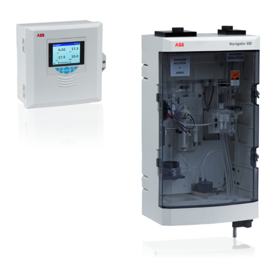
Navigator 500
Hydrazine analyzer
Measurement made easy
Introduction
The Navigator 500 hydrazine analyzer is designed to provide
continuous monitoring and control of power station boiler feed
water.
The analyzer comprises a Navigator 540 transmitter with multiple
wet-section capability for up to 4 wet-sections.
These Operating instructions provide installation, operation and
maintenance procedures for the Navigator 550 hydrazine
wet-section and a Navigator 540 transmitter.
For more information
Further publications for the Navigator 500 hydrazine analyzer
are available for free download from:
www.abb.com
(see links and reference numbers below) or by scanning this
code:
Navigator 550 hydrazine wet-section
Commissioning instructions
Navigator 540 transmitter
Commissioning instructions
search for or click on:
CI/AHM550-EN
CI/AWT540-EN
Advertisement
Table of Contents

Related Manuals for ABB Navigator 550


Summary of Contents for ABB Navigator 550
- Page 1 (see links and reference numbers below) or by scanning this wet-section capability for up to 4 wet-sections. code: These Operating instructions provide installation, operation and maintenance procedures for the Navigator 550 hydrazine wet-section and a Navigator 540 transmitter. search for or click on: Navigator 550 hydrazine wet-section...
- Page 2 We are an established world force in the design and manufacture of measurement products for industrial process control, flow measurement, gas and liquid analysis and environmental applications. As a part of ABB, a world leader in process automation technology, we offer customers application expertise, service and support worldwide.
-
Page 3: Table Of Contents
Safety precautions ...........3 Performing a calibration for the first time ....23 Potential safety hazards ...........3 Calibration options ..........24 1.2.1 Navigator 550 hydrazine wet-section – 5.2.1 Scheduled calibration ......... 24 electrical ............3 5.2.2 Monitoring calibration progress ....24 1.2.2 Navigator 550 hydrazine wet-section –... - Page 4 Navigator 500 Hydrazine analyzer 8 Maintenance ..............53 Chemical solutions ..........53 8.1.1 Reagent Solution – 5M (20% W/V) Sodium Hydroxide ..........53 8.1.2 Standard solution ........53 Scheduled servicing ..........53 8.2.1 Weekly ............53 8.2.2 6-monthly ........... 54 8.2.3 12-monthly ..........
-
Page 5: Health & Safety
1.2 Potential safety hazards 1.2.1 Navigator 550 hydrazine wet-section – electrical The Navigator 550 hydrazine wet-section operates on 24V DC supplied from the transmitter. There are no hazardous voltages present. 1.2.2 Navigator 550 hydrazine wet-section – chemical reagents Warning. -
Page 6: Safety Conventions
Do not proceed beyond a caution until all conditions have been met. Note. A note is used to indicate important information or instructions that should be considered before operating the equipment. 1.5 Symbols 1.5.1 Navigator 550 hydrazine wet-section Symbols that appear on this product are shown below: Functional earth (ground) terminal. -
Page 7: Navigator 540 Transmitter
ABB is committed to ensuring that the risk of any environmental damage or pollution caused by any of its products is minimized as far as possible. -
Page 8: Overview
2.1 Navigator 550 hydrazine wet-section The Navigator 550 hydrazine wet-section has been designed for use with an ABB Navigator 540 transmitter to provide continuous monitoring and control of power station boiler feed water, using an electro-chemical sensor to measure the amount of hydrazine in the boiler water. -
Page 9: Navigator 540 Transmitter
The Navigator 540 transmitter is designed for continuous monitoring and control of power station boiler feed water / steam condensate and must be used in conjunction with an associated ABB wet-section to measure levels of low level dissolved oxygen / sodium / hydrazine. -
Page 10: Installation
Navigator 500 Hydrazine analyzer 3 Installation 3.1 Installing the wet-section 3.1.2 Location For general location requirements refer to Fig. 3.1. Install in a 3.1.1 Sample requirements clean, dry, well ventilated and vibration-free location giving easy Ensure the sampling point is as close as possible to the access. -
Page 11: Mounting The Wet-Section
Navigator 500 Hydrazine analyzer 3.1.3 Mounting the wet-section Refer to Fig. 3.2 for wet-section dimensions. The wet-section weighs 4.5 kg (10 lb). Note. Clearance – the enclosure doors can open 180°. If mounting in a confined area, allow sufficient clearance for door opening. -
Page 12: Connecting The External Sample Inlet Line And Drains
Navigator 500 Hydrazine analyzer 3.1.4 Connecting the external sample inlet line and drains Note. Sample inlet and drain tubing from the funnel is customer-supplied. Keep sample outlet tubing as short and vertical as possible to enable the sample to drain freely during a calibration routine. Referring to Fig. -
Page 13: Connecting The Standard Solution 2 (High) And Reagent Tubing
Navigator 500 Hydrazine analyzer 3.1.5 Connecting the standard solution 2 (high) and reagent tubing Connections to the standard solution 2 (high) and reagent containers must be made on site. All other internal wet-section tubing connections are factory-made. 1. Fill the standard solution and reagent containers with the correct solutions – refer to Section Fig. 8.1, page 53, for solution details. -
Page 14: Installing The Transmitter
Navigator 500 Hydrazine analyzer 3.2 Installing the transmitter 3.2.1 Transmitter optional accessories 3.2.3 Panel mounting Optional accessories comprise: Dimensions in mm (in.) Cable gland kit (1.4) (3.6) 3.2.2 Transmitter location For transmitter general location requirements refer to Fig. 3.6. Install in a clean, dry, well ventilated and vibration-free location giving easy access. -
Page 15: Pipe Mounting
Navigator 500 Hydrazine analyzer 3.2.4 Pipe mounting 3.2.5 Wall mounting Dimensions in mm (in.) Dimensions in mm (in.) 214 (8.42) 213 (8.38) 200 (7.87) Fixing centers (7.64) (2.44) Ø6.4 (2.40) (0.25) Cable gland kit – optional Cable gland kit – optional Fig. -
Page 16: Electrical Connections - Wet-Section
Navigator 500 Hydrazine analyzer 3.4 Electrical connections – wet-section 3.4.1 Accessing the wet-section PCB This section is applicable only for multiple wet-section systems. Note. For single wet-section systems, the Modbus cable is connected to the wet-section at the factory – only transmitter connections are required. -
Page 17: Wet-Section Pcb Connections
Navigator 500 Hydrazine analyzer 3.4.2 Wet-section PCB connections Cable Color Terminal ID Description Note. Serial 24 V Refer to Section 3.5.2, page 18, for connection details at the transmitter. Black Serial cable connections at each additional Green Data +ve wet-section are made into the same terminal IDs as the factory-fitted serial cable. -
Page 18: Electrical Connections - Transmitter
Navigator 500 Hydrazine analyzer 3.5 Electrical connections – transmitter Warning. If the transmitter is used in a manner not specified by the Company, the protection provided by the equipment may be impaired. Remove all power from supply, relay, any powered control circuits and high common mode voltages before accessing or making any connections. -
Page 19: Accessing The Transmitter Connection Board
Navigator 500 Hydrazine analyzer 3.5.1 Accessing the transmitter connection board Note. Electrical connections at the wet-section connection board are identified in Section 3.4.2, page 15. Before fitting cable glands, identify the connections required and cable gland entries to be used. Referring to Fig. -
Page 20: Transmitter Connections
Navigator 500 Hydrazine analyzer 3.5.2 Transmitter connections I/O module 1 RS485 SMART SENSOR (shown fitted) INTERFACE MODULE ANALOGUE OUTPUT BOARD CM40/0215 ISS.1 CM40/0235 RELAY RELAY Optional OUT 3 OUT 4 I/O module 3 option card communications module [shown fitted]) I/O MODULE 2 I/O MODULE 3 I/O MODULE 3 –... -
Page 21: Setup
Navigator 500 Hydrazine analyzer 4 Setup This section describes how to set the analyzer up for first-time 4. Connect the hydrazine sensor (red) and temperature use. sensor (blue) electrical connectors corresponding color-coded sockets on the hydrazine sensor connector block. Caution. Do not attempt to setup the analyzer unless the wet-section and transmitter are fully installed and ready for 5. -
Page 22: Setting Flow Rates
Navigator 500 Hydrazine analyzer 4.3 Setting flow rates Warning. The sample is dosed with sodium hydroxide and the concentration, although low at first, increases if any spillage is left to evaporate. Take care to dispose of the outflow safely. The flow rates of standard solution and sample through the Blue wet-section are preset at the factory. - Page 23 Navigator 500 Hydrazine analyzer 3. Press the key to select the Enter Configuration menu 6. Press the key to select the Man. Valve Control menu and press the key (below the icon). and press the key (below the Select prompt). The Access Level page is displayed: The Man.
-
Page 24: Sample Flow Rate
Navigator 500 Hydrazine analyzer Referring to Fig. 4.2: 4.3.2 Sample flow rate 1. The flow rate of sample (from the constant head unit) 8. Use a 50 ml (1.7 fl. oz.) syringe to slowly draw solution through the sensor can now be checked. Ensure that from the sensor drain tube until any air bubbles are sample is flowing through the sensor rather than standard... -
Page 25: Calibration
Navigator 500 Hydrazine analyzer 5 Calibration 5.1 Performing a calibration for the first time This section describes how to calibrate the analyzer once it is operational. Calibration involves measuring the wet-section’s To perform a quick calibration from an Operator page: sensitivity to a solution containing a known hydrazine 1. -
Page 26: Calibration Options
Navigator 500 Hydrazine analyzer 4. Press the key (below the Yes prompt). 5.2 Calibration options The Calibration page is displayed with a bar graph 5.2.1 Scheduled calibration Automatic calibrations can be performed with a frequency of 1 indicating calibration progress: day to 1 month. -
Page 27: Abort Calibration
Navigator 500 Hydrazine analyzer 5.2.3 Abort calibration 5.3 Recovery period A calibration can be aborted by pressing the (Abort) key The recovery period allows time for the wet-section to return to while the Calibration page is displayed (see Section 5.1, page the Process Value after a calibration. -
Page 28: Operation Overview - Transmitter
Navigator 500 Hydrazine analyzer 6 Operation overview – transmitter 6.1 Front panel keys The transmitter is operated using the keys on the front panel. These enable local navigation and selection of software options on all displays, acknowledgement and data logging and monitoring. Prompts associated with active keys are displayed on each screen. Diagnostic messages are detailed in Appendix A.1, page 63, display icon descriptions are detailed in Section 6.10, page 37. -
Page 29: Transmitter Operation Modes
Navigator 500 Hydrazine analyzer 6.2 Transmitter operation modes The transmitter has 4 modes of operation – all modes are accessed from the Operator menu – see Fig. 6.2. Operating – used to display real-time wet-section values on Operating Pages – refer to Section 6.5, page 28. ... -
Page 30: Navigation Overview
Navigator 500 Hydrazine analyzer 6.4 Navigation overview Operator Operator Operator Operator Operator Page 1 Page 3 Page 4 Page 5 Page 2 Diagnostics Signals Chart Alarms Outputs View View View View View Calibration Alarm Audit Diagnostic Fig. 6.3 Menu navigation 6.5 Operating mode In operating mode, values from connected wet-sections are displayed on Operator Pages. - Page 31 Navigator 500 Hydrazine analyzer Fig. 6.5 shows an overview of Operator Pages 2 to 5. Each Operator Page displays the process value (PV) and temperature from a single wet-section. Fixed, color-coded, user-assignable tags (one for each fitted wet-section) and color-coded bargraphs aid identification of each wet-section.
-
Page 32: View Mode
Navigator 500 Hydrazine analyzer 6.6 View mode Pages displayed in View mode comprise: Diagnostics View – displays a list of diagnostic messages identified by priority and message – see Fig. 6.6 Alarms View – displays a list of alarms identified by priority (sequence number), source and status – see Fig. 6.7 ... -
Page 33: Log Mode
Navigator 500 Hydrazine analyzer Signal value / efficiency indicator Units Signals View 2012–04–15 10 : 31: 27 Value Sensor 1 Units Signal type Concentration 8.25 °C Temperature Sensor Output Flow Rate ml/min. Efficiency Last Efficiency Scroll for additional signals Fig. 6.9 Signals View Color-coded trace (1 for each wet-section) Process value... -
Page 34: Calibration Log Entries
Navigator 500 Hydrazine analyzer 6.7.1 Calibration log entries Possible calibration log entries along with a description are shown in Table 6.2. The possible Audit Log entries along with a description are shown in Table 6.3. The Diagnostic Log shows the history of diagnostic messages that have been displayed in the Diagnostic View;... -
Page 35: Logging
When handling the SD card / USB stick take care not to touch any exposed metal Note. ABB's DataManager software can be used to store contacts. and view data archived from the transmitter. -
Page 36: Sd Card / Usb Stick Insertion And Removal
Alternatively, you can carry out detailed graphical analysis of the Note. Data stored in the internal memory buffer can still be data on a PC using ABB’s DataManager data analysis software. transferred to the SD card / USB stick when the archive... -
Page 37: Log Files
Navigator 500 Hydrazine analyzer 6.8.5 Log files The Alarm Event, Calibration, Diagnostic and Audit logs are archived into the same file. The filenames are formatted as follows: Event logs: <ddmmyy><hhmmss><instrument tag>.AOO 6.8.6 Daylight saving Files containing data generated during the daylight saving period have '~DS' appended to the filename. -
Page 38: Password Security And Access Level
Navigator 500 Hydrazine analyzer 6.9 Password security and Access Level Passwords are entered at the Enter Password screen accessed via the Access Level – see Section 6.9.2, below. 6.9.1 Setting passwords Passwords can be set to enable secure access at 2 levels: Calibrate and Advanced. The Service level is password protected at the factory and reserved for factory use only. -
Page 39: Display Icons
Navigator 500 Hydrazine analyzer 6.10 Display icons 6.10.2 Title bar icons 6.10.1 Diagnostic icons Log mode – indicates that one of the View pages is currently displayed (Calibration, Alarm, Audit or Note. Diagnostic) When a diagnostic condition is detected the associated NAMUR icon plus the highest priority View mode –... -
Page 40: Log Icons
Navigator 500 Hydrazine analyzer 6.10.3 Log icons 6.10.4 Status bar icons Source: wet-section 1 (red) Operator menu – displays the Operator menu when S1 = sensor for wet-section 1 key is pressed. T1 = temperature for wet-section 1 Autoscroll – selected from the Operator menu Source wet-section 2 (green) (displayed when Autoscroll enabled). -
Page 41: Menu Descriptions
Type Note. Service level menus (not shown) are Serial Number Date of manufacture password-protected at the factory and intended for Hardware Revision Software Revision use by authorised ABB service technicians only. Fig. 7.1 Overview of hydrazine menus OI/AHM550–EN Rev. A... -
Page 42: Calibrate
Navigator 500 Hydrazine analyzer 7.1.1 Calibrate Used to calibrate the wet-section, adjust the Recovery Time and to enable / disable the Hold Menu Outputs function. Calibrate Access to the Calibrate menu is permitted via the Calibrate and Advanced levels only. Select Exit Menu... -
Page 43: Sensor Setup
Navigator 500 Hydrazine analyzer 7.1.2 Sensor Setup Used to set the wet-section tag, measurement units, operational range and filter type, enable / Menu disable the Flow Meter (optional) and energize the solenoid valve (via the Man.l Valve Control Sensor Setup menu). -
Page 44: Device Setup
Navigator 500 Hydrazine analyzer 7.1.3 Device Setup This level is used to access standard setup parameters. Menu Device Setup Select Exit Menu Comment Default Initial Setup Instrument Tag The device (transmitter) identification tag. Navigator Temperature Units Selects the temperature units displayed (°C or °F). °C Reset to Defaults Restores Device Setup parameters to their default settings. - Page 45 Navigator 500 Hydrazine analyzer …Range Change Setup Analog output operation Analogue output 2 is used for the range changing functionality and is scaled depending on the range selected. The mA range is set automatically to 4 to 20 mA. Analog output 2 Range Zero Span...
-
Page 46: Display
Navigator 500 Hydrazine analyzer 7.1.4 Display Used to select the display language, setup Operator page templates (1 to 5), enable diagnostic, Menu view and log functions, set the device’s display brightness / contrast and set the time and date. Display Select Exit Menu... - Page 47 Navigator 500 Hydrazine analyzer …Menu Comment Default Settings Sets the following display parameters. Brightness Increases / decreases the device’s brightness settings to suit local environmental conditions. Contrast Increases / decreases the device’s contrast settings to suit local environmental conditions. Date & Time Sets / formats the device’s date, local time and daylight saving start / end times: Date Format...
-
Page 48: Input/Output
Navigator 500 Hydrazine analyzer 7.1.5 Input/Output Input/Output level enables configuration of analog outputs, digital inputs and outputs and relays. Menu Input/Output Select Exit Menu Comment Default Analog Outputs The analog outputs can be configured to retransmit the process variable and temperature values and have a configurable range from 0 to 22 mA. - Page 49 Navigator 500 Hydrazine analyzer …Menu Comment Digital I/O See page 18 for digital I/O connections. Digital I/O 1 to 6 Type Sets the Digital I/O to operate as an output or an input: Off – no action taken. Output – the Digital I/O operates as an output. Volt Free –...
-
Page 50: Process Alarm
Navigator 500 Hydrazine analyzer 7.1.6 Process Alarm Used to configure up to 8 independent process alarms. Menu Process Alarm Select Exit Menu Comment Default Alarm 1 to 8 Source Selects the analog value for the process alarm source. None Type Selects the alarm type from: High Process ... -
Page 51: Media Card
Navigator 500 Hydrazine analyzer 7.1.7 Media Card Used to set the card on / off status, select the process data to be logged, enter file configuration Menu selection and save details and to format the media card. Media Card Media Card level menus are enabled only if an optional media card module is fitted. Select Exit Menu... -
Page 52: Communication
Navigator 500 Hydrazine analyzer 7.1.8 Communication The Communication level is enabled only if an optional communications module is fitted. Menu Communication Ethernet and Email menus are enabled only if a Ethernet communications module is fitted. Select Exit Menu Comment Default Profibus Slave Address Sets the device-specific slave address for identification on the network. -
Page 53: Device Info
Navigator 500 Hydrazine analyzer 7.1.9 Device Info Displays read-only factory-set details for the transmitter and connected wet-section(s). Menu Device Info Select Exit Menu Comment Default Transmitter Serial Number The transmitter’s serial number. Date of Manufacture The transmitter’s date of manufacture. Hardware Revision The transmitter’s hardware version number. -
Page 54: Analog Sources And Digital Input / Output Sources
Navigator 500 Hydrazine analyzer 7.2 Analog sources and digital input / output sources 7.2.1 Analog sources Source name* Description Hydrazine 1 (4) Measured concentration value for the associated wet-section. Temperature 1 (4) Measured temperature value for the associated wet-section. Table 7.1 Analog sources 7.2.2 Digital output sources Source name* Description... -
Page 55: Maintenance
Navigator 500 Hydrazine analyzer 8 Maintenance 8.1 Chemical solutions 8.1.2 Standard solution Warning. Hydrazine sulphate is an irritant to skin and eyes. Warning. Sodium Hydroxide is extremely caustic and must Avoid breathing the dust. Wear gloves, eye protection and a be handled with great care. -
Page 56: 6-Monthly
Navigator 500 Hydrazine analyzer 8.2.2 6-monthly 10. Hold the reagent tube over a suitably positioned 1. Replace the microporous disc in the dosing chamber – beaker and reconnect the reagent QD coupling see Section 8.2.4. enable the reagent to flow through the tube to displace any air bubbles. -
Page 57: Replacing Plastic Tubing
Navigator 500 Hydrazine analyzer 8.2.5 Replacing plastic tubing 6. Fit a 100 mm (4 in.) length of new tubing between the Warning. constant head unit outlet and solenoid valve. This wet-section contains caustic and other solutions 7. Fit new tubing to the sensor overflow drain barbed which must be handled with care. - Page 58 Navigator 500 Hydrazine analyzer Constant-head drain stubs (2) Reagent container Standard solution QD coupling container QD coupling Solenoid valve connections Hydrazine sensor base Reagent dosing chamber Fig. 8.3 Removing / Replacing tubing in wet-section Item Description Length mm (in.) Part number Quantity Drain tubing* (cut into 2 equal lengths of 240 mm [9.45 in.]): 2 x 240 (9.45)
-
Page 59: Shut-Down Procedure
Navigator 500 Hydrazine analyzer 8.3 Shut-down procedure If the wet-section needs to be shut down for longer than 1 week, perform the following procedure: 1. Turn sample flow off and allow the constant-head unit to drain. 2. Turn the hydrazine sensor plugs (electrical connectors), located on the side of the liquid handling panel, anti-clockwise and disconnect them by pulling them from the sockets. -
Page 60: Refurbishing The Hydrazine Sensor Assembly
Navigator 500 Hydrazine analyzer 8.4 Refurbishing the hydrazine sensor assembly 8.4.2 Dismantling and cleaning Referring to Fig. 8.5: Warning. The reagent used in the wet-section is extremely 1. Remove the 2 x 10-32 UNF blanking plugs caustic and must be handled with great care. Gloves, 2. -
Page 61: Cleaning The Platinum Anode And Sensor Ceramic
Navigator 500 Hydrazine analyzer 8.4.3 Cleaning the platinum anode and sensor ceramic 9. Ensure that the sample is flowing through the hydrazine Warning. Sodium Hydroxide is extremely caustic and must sensor at the correct rate – refer to Section 3.1.1, page 8. be handled with great care. -
Page 62: Specification - Analyzer
Navigator 500 Hydrazine analyzer 9 Specification – analyzer Measuring range Environmental data 0 to 1000 ppb Ambient operating temperature: 0 to 55 ºC (32 to 131 ºF) Ambient operating humidity: Units of measure Up to 95 % RH non-condensing ppb, µg/l, µg/kg Storage temperature: –... -
Page 63: Specification - Transmitter
Navigator 500 Hydrazine analyzer 10 Specification – transmitter Operation Connectivity / communications Display Ethernet (optional) 89 mm (3.5 in) color 1/4 VGA TFT, liquid crystal display (LCD) with 100BaseT, TCP/IP, HTTP, FTP, SMTP built-in backlight and brightness / contrast adjustment Language Data logging English, German, French, Italian, Spanish... -
Page 64: Specification - Wet-Section
Navigator 500 Hydrazine analyzer 11 Specification – wet-section Mechanical data Protection IP54 Dimensions Height – 480 mm (18.90 in) Width – 290 mm (11.41 in) – door shut Depth – 185 mm (7.28 in) door closed – minimum (excluding fixing brackets) Weight –... -
Page 65: Appendix A - Troubleshooting
Navigator 500 Hydrazine analyzer Appendix A – Troubleshooting A.1 Diagnostic messages The transmitter is programmed to display diagnostic messages Diagnostic Icon NAMUR Status to provide information on servicing requirements and any other conditions that develop during operation. Failure All diagnostic messages displayed on the transmitter are added to the transmitter's Audit Log. - Page 66 Navigator 500 Hydrazine analyzer Icon Diagnostic message Possible cause and suggested action Temperature sensor failure for wet-section1 (2, 3, 4). Temp Failure The temperature compensator or associated connections are either open-circuit or short-circuit – check (S1, S2, S3, S4) wiring at temperature compensator connections to the PCB. Calibrating Calibrating.Displayed during calibration of wet-section (1, 2, 3, 4), when wet-section is exposed to air.
-
Page 67: Checking The Temperature Input
Navigator 500 Hydrazine analyzer A.2 Checking the temperature input A.4 Simple electronic check 1. Check that the wet-section responds to a temperature In the unlikely event that a problem is encountered with the input. Disconnect the Pt1000 temperature compensator wet-section, use a current (µA) source and a resistance box to leads in the wet-section PCB (see Section. -
Page 68: Unscheduled Servicing
Navigator 500 Hydrazine analyzer A.5 Unscheduled servicing A.5.1 Wet-section malfunction Diagnostic messages on the display are used to indicate 3. Check that the standard solution value entered into the abnormal wet-section operation – refer to Appendix A.1, page wet-section is correct for the solution used. 4. -
Page 69: Appendix B - Multiple Wet-Section Setup
Navigator 500 Hydrazine analyzer Appendix B – Multiple wet-section setup A single Navigator 500 transmitter can monitor up to 4 wet-sections. The wet-sections can be any combination of the three Navigator 500 parameters – sodium, low level dissolved oxygen and hydrazine. Note that the transmitter cannot monitor more than 1 wet-section if the wet-section is a multi-stream sodium. -
Page 70: Serial Connections
Navigator 500 Hydrazine analyzer B.2 Serial connections Each wet-section must be connected in a 'daisy chain' format as shown in Fig. B.2. Navigator 540 Wet-section 1 Wet-section 2 Wet-section 3 Wet-section 4 Black Green White Screen Fig. B.2 Serial connections Note. -
Page 71: Appendix C - Spare Parts
Navigator 500 Hydrazine analyzer Appendix C – Spare parts C.1 Navigator 500 hydrazine consumables Part No. / Type Usage / Volume Part No. Description Provides 4 to 8 weeks of continuous AW503 051 PCB housing seals operation. AWRS5000201 Shelf life 2 years. Hydrazine reagent Also available as a kit (AWRK5000211), see below. - Page 72 Navigator 500 Hydrazine analyzer Part No. Description Part No. Description AW503 058 Sensor connector block AW503 066 Sensor mounting kit (including fasteners) AW503 067 Tundish assembly AW503 060 Dosing chamber assembly (including bracket and fasteners) AW503 068 Flowmeter – hydrazine AW503 061 Dosing chamber micro-porous disc and O-rings (2 of each O-ring)
- Page 73 Navigator 500 Hydrazine analyzer Part No. Description Part No. Description AW503 072 Caln tank assembly AW503 085 Cable assembly – pressure switch AW503 086 Cable assembly – flowmeter AW503 073 Reagent tank assembly Modbus cable assembly: AW503 090 1.5 m (4.9 ft.) AW503 091 5 m (16.4 ft.) AW503 092...
-
Page 74: Navigator 540 Transmitter
Navigator 500 Hydrazine analyzer C.3 Navigator 540 transmitter Part No. Description Part No. Description AW500 050 AWT processor board spares kit AW500 055 AWT USB media PCB spares kit AW500 056 Door assembly spares kit AW500 051 AWT main board spares kit AW500 052 AWT sensor input PCB (Digital RS485) AW500 058... - Page 75 — Food & Beverage offices for details on your nearest Service and Repair Centre. — Manufacturing — Metals and Minerals — Oil, Gas & Petrochemical ABB Limited — Pulp and Paper Tel: +44 (0)1453 826661 Drives and Motors Fax: +44 (0)1453 829671 —...
- Page 76 Oldends Lane notice. With regard to purchase orders, the agreed Stonehouse particulars shall prevail. ABB does not accept any Gloucestershire GL10 3TA responsibility whatsoever for potential errors or possible lack of information in this document.
Need help?
Do you have a question about the Navigator 550 and is the answer not in the manual?
Questions and answers