
Subscribe to Our Youtube Channel
Related Manuals for WEG MVW3000


Summary of Contents for WEG MVW3000
- Page 1 Motors | Automation | Energy | Transmission & Distribution | Coatings Medium Voltage Frequency Inverter MVW3000 Programming Manual...
- Page 3 Programming Manual Series: MVW3000 Software version: 1.0X Language: English Document Number: 10004771632 / 00 Build 744 Publication Date: 08/2017...
- Page 5 Summary of Reviews Version Revsion Description 1.0X First edition.
-
Page 7: Table Of Contents
MESSAGES OF ALARMS AND FAULTS ................0-33 1 SAFETY INSTRUCTIONS ............1-1 SAFETY WARNINGS IN THE MANUAL ................. 1-1 SAFETY WARNINGS ON THE PRODUCT ..............1-1 IDENTIFICATION LABEL OF THE MVW3000 ..............1-2 PRELIMINARY RECOMMENDATIONS ................1-2 2 GENERAL INFORMATION ............2-1 ABOUT THE MANUAL....................2-1 SOFTWARE VERSION .................... - Page 8 Contents 6 DIAGNOSTICS AND TROUBLESHOOTING ........6-1 ALARMS, FAULTS AND POSSIBLE CAUSES ..............6-1 INFORMATION FOR CONTACTING TECHNICAL SUPPORT .......... 6-56 PREVENTIVE MAINTENANCE ................... 6-56 6.3.1 Preventive Maintenance During Operation............6-56 6.3.2 Preventive Maintenance with Complete Stop/De-energization ......6-57 SAFE DE-ENERGIZATION INSTRUCTIONS ..............6-58...
-
Page 9: Quick Reference Of Parameters And Faults
P0012 Digital inputs DI1 to DI10 status P0013 Digital outputs DO1 to RL5 status P0018 Value of analog input AI1 (single-pole, Read-only parameter (%) MVC4) P0019 Value of analog input AI2 (two-pole Read-only parameter (%) MVC4 board) MVW3000 | 0-9... - Page 10 0.0 to 999.0 s 100.0 s P0101 Deceleration time 0.0 to 999.0 s 180.0 s P0102 Acceleration time 2nd ramp 0.0 to 999.0 s 100.0 s P0103 Deceleration time 2nd time 0.0 to 999.0 s 180.0 s MVW3000 | 0-10...
- Page 11 Overload current at 50 % 0.0 to 3420.0 A 126.0 A 4-21 (2)(5) P0158 Overload current at 5 % 0.0 to 3420.0 A 70.0 A 4-21 P0159 Temperature alarm I x t 0 to 100 % 80 % 4-22 MVW3000 | 0-11...
- Page 12 2 = Not Used 3 = Reset P0043: It resets the enabled time counter. 4 = Reset P0044: It resets the MWh counter. 5 = Load WEG - 60 Hz: It reset all the parameters to the 60 Hz factory default values. P0206...
- Page 13 Selection of JOG Source LOCAL Situa- 0 = Disable 4-31 tion 1 = HMI 2 = Digital inputs DI3 to DI10 (P0265 to P0272) 3 = Serial 4 = Fieldbus 5 = PLC 6 = Graphic HMI MVW3000 | 0-13...
- Page 14 P0240 Analog input AI2 offset (bipolar MVC4 -100.0 to 100.0 % 0.0 % 4-40 board) P0241 AI3 signal function 0 = P0221/P0222 4-40 1 = Not Used 2 = Maximum torque current 3 = PID process variable MVW3000 | 0-14...
- Page 15 14 = Trace function channel 4 15 = Trace function channel 5 16 = Trace function channel 6 17 = Trace function channel 7 18 = Trace function channel 8 19 = Inverter Temperature 20 = PLC 21 = Inverter output voltage MVW3000 | 0-15...
- Page 16 14 = Trace function channel 4 15 = Trace function channel 5 16 = Trace function channel 6 17 = Trace function channel 7 18 = Trace function channel 8 19 = Inverter Temperature 20 = PLC 21 = Inverter output voltage MVW3000 | 0-16...
- Page 17 21 = RL2 Timer 22 = RL3 Timer 23 = No Alarm in the Redundant Ventilation Set A 24 = No Alarm in the Redundant Ventilation Set B 25 = Initiates Synchronous Transfer 26 = Ventilation OK MVW3000 | 0-17...
- Page 18 21 = RL2 Timer 22 = RL3 Timer 23 = No Alarm in the Redundant Ventilation Set A 24 = No Alarm in the Redundant Ventilation Set B 25 = Initiates Synchronous Transfer 26 = Ventilation OK MVW3000 | 0-18...
- Page 19 16 = Not used 17 = Not used 18 = Not used 19 = Parameterization Disabling 20 = Not used 21 = RL2 Timer 22 = RL3 Timer 23 = Initiates Synchronous Transfer 24 = Ventilation OK MVW3000 | 0-19...
- Page 20 19 = No Motor Fault 20 = No Motor Alarm 21 = No Alarm in the Redundant Ventilation Set A 22 = No Alarm in the Redundant Ventilation Set B 23 = Initiates Synchronous Transfer 24 = Ventilation OK MVW3000 | 0-20...
- Page 21 27 = Without error with delay 28 = No Alarm 29 = Not used 30 = Redundant ventilation 31 = Not used 32 = Circuit Break ON (Input Circuit Breaker ON) 33 = Transference OK 34 = Synchronism OK 35 = Serial MVW3000 | 0-21...
- Page 22 27 = Without error with delay 28 = No Alarm 29 = Not used 30 = Redundant ventilation 31 = PLC 32 = Circuit Break ON (Input Circuit Breaker ON) 33 = Transference OK 34 = Synchronism OK 35 = Serial MVW3000 | 0-22...
- Page 23 27 = Without error with delay 28 = No Alarm 29 = Timer 30 = Redundant ventilation 31 = PLC 32 = Circuit Break ON (Input Circuit Breaker ON) 33 = Transference OK 34 = Synchronism OK 35 = Serial MVW3000 | 0-23...
- Page 24 30 = Redundant ventilation 31 = Not used 32 = Circuit Break ON (Input Circuit Breaker ON) 33 = Transference OK 34 = Synchronism OK 35 = Serial P0283 RL2 ON time 0.0 to 300.0 s 0.0 s 4-57 MVW3000 | 0-24...
- Page 25 6 = DeviceNet 6 I/O 7 = Modbus-RTU 2 I/O 8 = Modbus-RTU 4 I/O 9 = Modbus-RTU 6 I/O 10 = DeviceNet Drive Profile 11 = Ethernet 2 I/O 12 = Ethernet 4 I/O 13 = Ethernet 6 I/O MVW3000 | 0-25...
- Page 26 Factory Pag. setting P0312 Type of serial protocol 0 = WEG Protocol 4-60 1 = Modbus-RTU, 9600 bps, no parity 2 = Modbus-RTU, 9600 bps, odd parity 3 = Modbus-RTU, 9600 bps, even parity 4 = Modbus-RTU, 19200 bps, no parity...
- Page 27 0 to 200 % 100 % 4-65 P0517 Full scale of online graphic 2 0 to 200 % 100 % 4-65 P0520 Pid proportional gain 0.0 to 7.999 4-66 P0521 PID integral gain 0.0 to 9.999 4-66 MVW3000 | 0-27...
- Page 28 -32768 to 32767 4-73 board) P0665 Fast analog output offset AO3 (MVC3 -32768 to 32767 4-74 board) P0666 Fast analog output offset AO4 (MVC3 -32768 to 32767 4-74 board) P0721 Analog input AI5 function 0 = P221/P222 4-74 MVW3000 | 0-28...
- Page 29 DC link voltage of cell W6 Read-only parameter (V) 4-77 ◦ P1050 Temperature on the power module of Read-only parameter ( 4-78 cell U1 ◦ P1051 Temperature on the power module of Read-only parameter ( 4-78 cell U2 MVW3000 | 0-29...
- Page 30 Temperature on the board of cell U4 Read-only parameter ( 4-79 ◦ P1354 Temperature on the board of cell U5 Read-only parameter ( 4-79 ◦ P1355 Temperature on the board of cell U6 Read-only parameter ( 4-79 MVW3000 | 0-30...
- Page 31 Bypass of the cell V3 0 = Disable 4-82 1 = Bypassed (1)(7) P1715 Bypass of the cell V4 0 = Disable 4-82 1 = Bypassed (1)(7) P1716 Bypass of the cell V5 0 = Disable 4-82 1 = Bypassed MVW3000 | 0-31...
- Page 32 (4) Values may change as a function of the parameter P0296 (Inverter rated voltage). (5) Values may change as a function of the parameter P0295 (Inverter rated current). (7) Parameter can only be changed with input cubicle opened. MVW3000 | 0-32...
-
Page 33: Messages Of Alarms And Faults
MESSAGES OF ALARMS AND FAULTS The faults of the MVW3000 can be subdivided into Alarms (Axxxx) and Faults (Fxxxx). In general, the alarms serve to indicate a situation that, if not corrected, can lead the inverter to a stop by fault. A signalized fault indicates a situation that caused the inverter to be disabled (the main circuit breaker may open or not, depending on the type of fault). - Page 34 F0316 Ground fault for neutral shift F0317 Ground fault for current leak F0320 Vab measurement feedback fault F0321 Vbc measurement feedback fault F0323 Ib measurement feedback fault F0324 Ic measurement feedback fault F0325 Vuv measurement feedback fault MVW3000 | 0-34...
- Page 35 Cell U2 neutral pulse feedback 6-10 F0436 Cell U2 electronics power supply 6-11 A0437 Cell U2 input overvoltage 6-11 F0438 Cell U2 input overvoltage 6-11 A0439 Cell U2 input undervoltage 6-11 F0440 Cell U2 input undervoltage 6-11 MVW3000 | 0-35...
- Page 36 F0479 Defective temperature sensor or undertemperature on cell U4 IGBT 6-14 F0480 Cell U4 phase IGBT 6-14 F0481 Cell U4 neutral IGBT 6-14 F0483 Cell U4 phase pulse feedback 6-14 F0485 Cell U4 neutral pulse feedback 6-14 MVW3000 | 0-36...
- Page 37 Firmware update or PLD cell U5 6-17 F0525 Cell U6 DC link overvoltage 6-18 F0526 Cell U6 DC link undervoltage 6-18 A0527 Overtemperature on cell U6 IGBT module 6-18 F0528 Overtemperature on cell U6 IGBT module 6-18 MVW3000 | 0-37...
- Page 38 Cell U7 modulation synchronism 6-21 F0567 Cell U7 bypass system 6-21 F0568 Communication with cell U7 6-21 F0570 Incompatible cell U7 firmware 6-21 F0571 Incomp. cell U7 model 6-21 F0572 DC link inbal.or insulat. cell U7 6-21 MVW3000 | 0-38...
- Page 39 F0611 Cell V1 electronics power supply 6-25 A0612 Cell V1 input overvoltage 6-25 F0613 Cell V1 input overvoltage 6-25 A0614 Cell V1 input undervoltage 6-25 F0615 Cell V1 input undervoltage 6-25 F0616 Cell V1 modulation synchronism 6-25 MVW3000 | 0-39...
- Page 40 Defective temperature sensor or undertemperature on cell V3 IGBT 6-28 F0655 Cell V3 phase IGBT 6-28 F0656 Cell V3 neutral IGBT 6-28 F0658 Cell V3 phase pulse feedback 6-28 F0660 Cell V3 neutral pulse feedback 6-28 F0661 Cell V3 electronics power supply 6-29 MVW3000 | 0-40...
- Page 41 Cell V5 DC link overvoltage 6-32 F0701 Cell V5 DC link undervoltage 6-32 A0702 Overtemperature on cell V5 IGBT module 6-32 F0703 Overtemperature on cell V5 IGBT module 6-32 F0704 Defective temperature sensor or undertemperature on cell V5 IGBT 6-32 MVW3000 | 0-41...
- Page 42 6-35 F0743 Communication with cell V6 6-35 F0745 Incompatible cell V6 firmware 6-35 F0746 Incompatible cell V6 model 6-35 F0747 Voltage unbalance on the capacitors or cell V6 insulation defective 6-35 F0748 Cell V6 firmware update 6-35 MVW3000 | 0-42...
- Page 43 6-39 A0787 Cell V8 input overvoltage 6-39 F0788 Cell V8 input overvoltage 6-39 A0789 Cell V8 input undervoltage 6-39 F0790 Cell V8 input undervoltage 6-39 F0791 Cell V8 modulation synchronism 6-39 F0792 Cell V8 bypass system 6-39 MVW3000 | 0-43...
- Page 44 Cell W2 phase IGBT 6-42 F0831 Cell W2 neutral IGBT 6-42 F0833 Cell W2 phase pulse feedback 6-42 F0835 Cell W2 neutral pulse feedback 6-42 F0836 Cell W2 electronics power supply 6-43 A0837 Cell W2 input overvoltage 6-43 MVW3000 | 0-44...
- Page 45 Cell W4 DC link undervoltage 6-46 A0877 Overtemperature on cell W4 IGBT module 6-46 F0878 Overtemperature on cell W4 IGBT module 6-46 F0879 Defective temperature sensor or undertemperature on cell W4 IGBT 6-46 F0880 Cell W4 phase IGBT 6-46 MVW3000 | 0-45...
- Page 46 F0920 Incompatible cell W5 firmware 6-49 F0921 Incompatible cell W5 model 6-49 F0922 Voltage unbalance on the capacitors or cell W5 insulation defective 6-49 F0923 Cell W5 firmware update 6-49 F0925 Cell W6 DC link overvoltage 6-50 MVW3000 | 0-46...
- Page 47 6-53 F0963 Cell W7 input overvoltage 6-53 A0964 Cell W7 input undervoltage 6-53 F0965 Cell W7 input undervoltage 6-53 F0966 Cell W7 modulation synchronism 6-53 F0967 Cell W7 bypass system 6-53 F0968 Communication with cell W7 6-53 MVW3000 | 0-47...
- Page 48 6-55 F0997 Voltage unbalance on the capacitors or cell W8 insulation defective 6-55 F0998 Cell W8 firmware update 6-55 NOTE! Note found in the alarm and fault quick reference: (1) It does not open the circuit breaker. MVW3000 | 0-48...
-
Page 49: Safety Instructions
This product neither intended for applications whose purpose is to ensure physical integrity and/or life of people, nor for any other application in which a fault of the MVW3000 may create a situation of risk to the physical integrity and/or life of people. The designer who applies the MVW3000 must provide ways to ensure the safety of the installation even in case of a failure of the servo drive. -
Page 50: Identification Label Of The Mvw3000
SAFETY INSTRUCTIONS Connection of the shield to the ground. 1.3 IDENTIFICATION LABEL OF THE MVW3000 The identification label of the MVW3000 is located inside the product Control Panel. The label contains important information on the inverter. AUTOMATION UNIT SWITCHGEAR AND CONTROLGEAR TYPE: MVW3000 Ur: 7.2 kV... - Page 51 If necessary, first touch the grounded metallic frame or use a proper grounding strap. Do not execute any applied potential test on the inverter! If necessary, contact WEG. NOTE! Frequency inverters may interfere with other electronic equipment. Follow the recommended proce- dures to minimize those effects.
- Page 52 SAFETY INSTRUCTIONS MVW3000 | 1-4...
-
Page 53: General Information
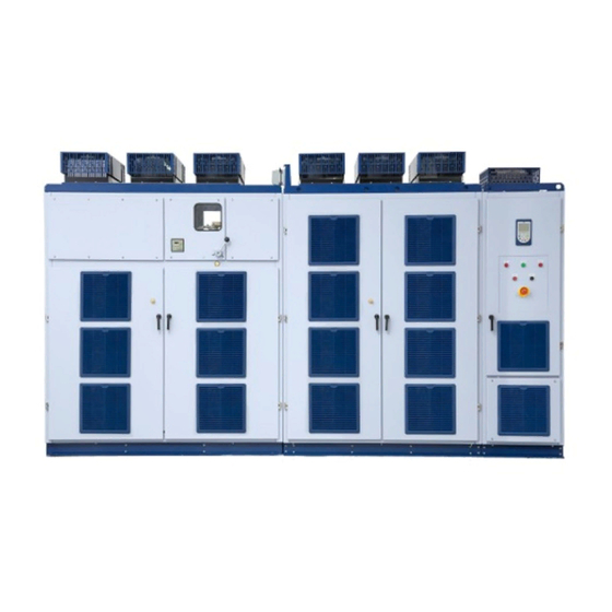
MVW3000. This manual must be used together with the User’s Manual. 2.1 ABOUT THE MANUAL This manual contains 6 chapters, which have a logical sequence for the user to program and operate the MVW3000: Chapter 1 SAFETY INSTRUCTIONS on page 1-1 . - Page 54 Manual, Figure 4.3, page 4-3 and tables 4.1 to 4.12 on pages 4-3 and 4-4. For models with rated voltage above 8000 V, contact WEG. Figure 2.1: General illustration of the MVW3000 panel (Frame B6) WARNING! It is very important to check that the inverter software version is the same as indicated on the first page of this manual.
-
Page 55: Keypad (Hmi) Operation
Edition: new keys to speed up the parameter edition. The graphic HMI design, improvements and new functions present operation, navigation and programming similar to the HMI used with the CFW-11 line, making its use even easier to those familiar with that WEG product line. On-line help available... -
Page 56: Starting The Use Of The Graphic Hmi
(38400 bps, no parity, with 2 stop bits), using as the physical layer the channel. The Graphic HMI works as the communication master. When the panel is energized, the Graphic HMI performs a parameter initialization with the MVC4 board. During this process the firmware versions of the Graphic HMI and of the MVW3000 control boards are exhibited. -
Page 57: Graphic Hmi Basic Visualization Modes
Motor Speed (rpm). Footer: Time. Function of the 2 softkeys. The various modules or visualization screens of the graphic HMI can be classified in 6 different basic types: 1 parameter. 2 or 3 parameters. 4 to 6 parameters. Navigation: MVW3000 | 3-3... -
Page 58: Structure Of The Parameter Groups
(Table 3.2 on page 3-7). The navigation through these levels is done by means of the softkeys SK1 [Return] and SK2 [Select]. In order to select one group the Prog/Enter key or the softkey SK2 [Selec.] can be used. MVW3000 | 3-4... -
Page 59: Sequential Access Mode
(provided that the respective parameter is active). 1800rpm Motor Rdy Speed Reference P0001: 1800 rpm Motor Speed P0002: 0 rpm Motor Current P0003: 0.0 A Motor Frequency P0005: 0 Hz Exit 13:38 Selec. Figure 3.6: Sequential parameter list MVW3000 | 3-5... -
Page 60: Parameter Groups Access Mode
In order to enter this parameter access mode it is necessary to press the [Menu] softkey (available in the monitoring mode) and select <03 Parameter Groups>. In this mode the parameters are accessed according to their group or to the function to which they belong. Refer to the group structure in table 3.2 on page 3-7. MVW3000 | 3-6... - Page 61 Skip Speed Local/Remote Configuration Status/Commands DeviceNet Communication Serial RS232/485 Anybus Profibus DP Trace Function Special Function Changed Parameters Backup Parameters Analog inputs Analog outputs I/O Configuration Digital Inputs Digital/Relay Outputs Fault History Basic Application Oriented Start-up Auto-Setup MVW3000 | 3-7...
-
Page 62: Parameter Edition
1800rpm Motor Rdy P0100 Acceleration Time 180.0 Exit 13:38 Save Figure 3.8: Numerical edition 3.3.2 Alphanumerical edition In the edition of message type parameters, the cursor can be moved by using the keys. MVW3000 | 3-8... -
Page 63: Configuring The Graphic Hmi
The automatic programming of the parameters described above may be done through the parameter P0491 “Graphic HMI configuration” (Menu <10 Auto-Setup> or <29 HMI>). Table 3.3: Graphic HMI commands selection Option Description Inactive Local Graphic HMI Remote Graphic HMI MVW3000 | 3-9... -
Page 64: Configuring The Monitoring Mode Read-Only Parameters
For the [Graphic] softkey to be available, it is necessary that at least one read-only parameter be programmed for watch (P0512...P0519). 1800rpm Motor Rdy 100% P0002= 1253 rpm P0003= 20.0A Exit 13:38 Figure 3.10: Graphic function visualization example MVW3000 | 3-10... -
Page 65: Alarms And Faults
3.5 ALARMS AND FAULTS 3.5.1 Alarms/Faults Screen When fault or alarm occurs in the MVW3000, the Graphic HMI enters the error warning mode (refer to Figure 3.11 on page 3-11). The HMI stays in this error warning mode until the user selects [Return] or error [Reset], through the correspondent softkeys. -
Page 66: Note Screen
Notes do not generate events such as inverter stopping. 3.5.3 Error Log The parameter P0067 keeps the information on the inverter last 100 occurred errors (in a similar manner to the conventional HMI), according to Figure 3.12 on page 3-12. MVW3000 | 3-12... -
Page 67: Error Log
Ratio of the input current CTs > It sets the the ratio of the current transformers used in the measurement of the input current. > Set according to the current transformer nameplate data. Exit 13:38 Figure 3.15: Help function visualization mode MVW3000 | 3-13... - Page 68 KEYPAD (HMI) OPERATION MVW3000 | 3-14...
-
Page 69: Detailed Parameter Description
The indication scale can be changed via P0208. P0002 - Motor Speed Description: It indicates the real motor speed value in rpm (with filter with time constant of 0.5 s). The indication scale can be changed via P0208. MVW3000 | 4-1... - Page 70 12 = ‘Test Mode’ indicates that the inverter is in a transitory state to test mode or to self-tuning. 13 = ‘Inv. Test’ indicates that the inverter is in a general test state. 14 = Not implanted in this software version. MVW3000 | 4-2...
- Page 71 P0009 - Motor Torque Description: It indicates the torque value produced by the motor. It is calculated as follows: × 100 P0009 = rated Being: = Present motor torque current. Scalar control mode: = Rated inverter torque current. rated MVW3000 | 4-3...
- Page 72 See the description of parameters P0234 (Analog input AI1 gain (unipolar MVC4 board)) to P0247 (Analog input AI4 offset (bipolar EBA board)). Analog input AI2 has a filter that distinguishes it from the others (see P0248 (Analog input AI2 filter (bipolar MVC4 board))). MVW3000 | 4-4...
- Page 73 The module serial configuration must be set as follows: Tecsystem: Baud rate: 19200 bps (SW1.dip1 = 1 / SW1.dip2 = 1). Parity: even (SW1.dip3 = 1 / SW1.dip4 = 1). Slave address: 1 (SW2.dip7 to dip1 = 0 / SW2.dip0 = 1). Pextron: MVW3000 | 4-5...
- Page 74 This parameter is only visible na HMI when the redundant Ventilation function is active, P0140 > 0. P0042 - Time powered counter Description: It indicates the total hours the inverter remained powered. This value is kept even when the inverter is powered down. MVW3000 | 4-6...
- Page 75 (e.g.: Inveter ready) and date/time at the moment the error occurred. For instance, in order to access the 8th last occurred error, proceed in the following manner: 1. Access the parameter P0067. 2. Press the key. 3. Use the keys to access the eighth record. MVW3000 | 4-7...
- Page 76 The maximum supported year is 2099. Only smaller values must be set. Procedure to adjust the date: 1. Press the key 2. Use the keys to select the field. 3. Use the keys to change to the ne date. MVW3000 | 4-8...
- Page 77 P0104 - S Ramp Adjustable range: 0.0 to 100.0 % Factory setting: 0.0 % Description: This parameter allows the acceleration and deceleration ramps to have a non-linear profile, similar to an ”S”, as shown in Figure 4.2. MVW3000 | 4-9...
- Page 78 P0123 - Speed reference for JOG- Adjustable range: P0121 = 0 to 7200 rpm Factory setting: P0121 = 90 rpm P0122 = 0 to 8192 rpm P0122 = 150 rpm P0123 = 0 to 8192 rpm P0123 = 150 rpm MVW3000 | 4-10...
- Page 79 DI3 to DI10 P0265 to P0272 = JOG- When activating the JOG+/JOG- function, the speed reference in P0122/P0123 will be added (without ramp) to the other references to generate the total reference - see Figure 4.19 on page 4-33. MVW3000 | 4-11...
- Page 80 Table 4.6: Selection of the Multispeed function via digital inputs Programming DIx enabled P0266 = 7 P0267 = 7 P0268 = 7 Table 4.7: Multispeed Reference 8 speeds 4 speeds Speed reference 2 speeds P0124 P0125 P0126 P0127 P0128 P0129 P0130 P0131 MVW3000 | 4-12...
- Page 81 P0134 = 1800 rpm Description: It defines the maximum/minimum values of speed reference for the motor when the inverter is enabled. Valid for any type of reference signal. For details on the actuation of P0133 see P0233 (Dead Zone). MVW3000 | 4-13...
- Page 82 (F0070, F0071 and F0072). The maximum value of increase for the output voltage is equal to 20 % of the rated voltage, in the null frequency, when P0136 = 100. Setting 0 means inactive function. MVW3000 | 4-14...
- Page 83 This parameter is only visible on the HMI when: the control type is scalar, P0202 = 0, 1 or 2 (V/F control). P0137 - Addition on the automatic torque curve Adjustable range: 0 to 1000 Factory setting: MVW3000 | 4-15...
- Page 84 P0138 allows the user to set precisely the slip compensation on the MVW3000. Once P0138 is set, the inverter will keep the speed constant even with load variations by means of the automatic setting of voltage and frequency.
- Page 85 DO2, or RL1 to RL5) for the selection of the active set, and two digital inputs (DI1 to DI10) for set A and set B operation failure. A ventilation failure alarm is activated when one of the sets fails (alarm A0094 or A0114 for set A or set B, respectively). MVW3000 | 4-17...
- Page 86 (set in P0403) is different from 60 Hz, the standard value of P0144 may become inadequate, and it may cause problems in the motor start. If it is necessary to increase the starting torque, increase the value of P0144 gradually. Procedure to parameterize the ”Adjustable V/F” function: 1. Disable the inverter. MVW3000 | 4-18...
- Page 87 4-20. This voltage regulation of the DC link (ramp holding) tries to avoid the locking of the inverter due to errors related to overvoltage on the DC link when the deceleration occurs with high inertia loads or with short deceleration times. MVW3000 | 4-19...
- Page 88 If P0152 = 0.00 and P0151 different from the maximum value, the ramp holding function is active. Refer to P0151 fro V/F. P0152 multiplies the voltage error of the DC link, that is, error = present DC link - P0151. P0152 is typically used to prevent overvoltage in applications with eccentric loads. MVW3000 | 4-20...
- Page 89 (motor with separated ventilation). I(A) Motor current (P0003) Overload current t = 30 Time (s) 0 15 30 60 75 Figure 4.15: Function I x t - overload detection MVW3000 | 4-21...
- Page 90 If the current exceeds the value set in P0169, the motor speed will be reduced following the deceleration ramp until the current is below the value set in P0169. When the overload disappears, the speed goes back to the normal value. MVW3000 | 4-22...
- Page 91 It expresses the percentage of the modulation index from which the motor field weakening occurs. P0181 - Magnetization mode Adjustable range: 0 to 1 Factory setting: Description: It configures the magnetization mode of the machine to be driven. Table 4.9: Magnetization mode P0181 Function General enable Start/Stop MVW3000 | 4-23...
- Page 92 It defines the control type to be used by the inverter. Table 4.12: Control Type P0202 Function V/F 60 Hz V/F 50 Hz Adjustable V/F (refer to P0142 to P0146) NOTE! This parameter can only be changed with the motor stopped. MVW3000 | 4-24...
- Page 93 Parameters P0295 (Inverter rated current), P0296 (Inverter rated voltage), P0308 (Serial address) and P0201 (Language selection) will not be changed when P0204 = 5 (Load WEG - 60 Hz: It reset all the parameters to the 60 Hz factory default values.).
- Page 94 Speed = present speed in rpm. Sync. speed = 120 x P0403 / poles. Poles = 120 x P0403 / P0402, it may be equal to 2, 4, 6, 8 or 10. Reference = speed reference in rpm. MVW3000 | 4-26...
- Page 95 P0535, so that the inverter will be able to leave the zero speed disable. Table 4.18: Condition for disab. output by zero speed P0212 Function P0001 (N*) > P0291 or P0002 (N) > P0291 P0001 (N*) > 0 MVW3000 | 4-27...
- Page 96 It defines the origin of the command that will select between the Local situation and the Remote situation. With the factory default settings, the key of the HMI selects between Local and Remote. After powering up the inverter, it will start in Local mode (Local Default). MVW3000 | 4-28...
- Page 97 Sum of Analog Inputs (AI1’ + AI2’) > 0 (Negative values are zeroed) Sum of Analog Inputs (AI1’ + AI2’) Electronic Potentiometer (E.P.) Multispeed (P0124 to P0131) Serial Fieldbus Analog Input AI5’ (P0721 to P0724) Graphic HMI MVW3000 | 4-29...
- Page 98 When the DIx inputs have the FORWARD/REVERSE function, the HMI keys will remain inactive regardless of the value set in P0224 (Start/Stop Selection LOCAL Situation). Table 4.23: Start/Stop Selection LOCAL Situation P0224 Function l and keys Digital input DIx Serial Fieldbus Graphic HMI MVW3000 | 4-30...
- Page 99 (Forward default) key (Reverse default) Digital Input DI2 (P0264 = 0) Serial (Forward default) Serial (Reverse default) Fieldbus (Forward default) Fieldbus (Reverse default) AI4 Polarity Forward PLC Reverse PLC Graphic HMI key (Forward) Graphic HMI key (Reverse) MVW3000 | 4-31...
- Page 100 P0228 - JOG Selection - REMOTE Situation Adjustable range: 0 to 6 Factory setting: Description: It defines the origin of the JOG command in the REMOTE situation. The speed reference value for JOG is provided by parameter P0122. MVW3000 | 4-32...
- Page 101 DIRECTION OF ROTATION (P0223) (P0220) LOCAL/REMOTE RUN/STOP SELECTION (P0224) REFERENCE (P0225) LOCAL REFERENCE REFERENCE REFERENCE REMOTE COMMANDS LOCAL COMMANDS COMMANDS COMMANDS REMOTE REMOTE REFERENCE (P0222) DIRECTION OF ROTATION (P0226) RUN/STOP (P0227) (P0228) Figure 4.19: LOCAL/REMOTE situation block diagram MVW3000 | 4-33...
- Page 102 JOG + P0122 Direction of rotation P0102, P0103 JOG - P0123 P0134 = maximum ref. P0133 = minimum ref. P0163 P0164 P0134 2nd Ramp Total reference Read-only parameters P0133 P0001 P0002 P0005 P0133 P0100, P0101 Reference P0134 Commands and Reference limits reference Fast stop Run/Stop...
- Page 103 When the “DISABLE GENERAL” stop mode is programmed, only drive the motor if it is stopped or set the necessary time for which the inverter is disabled (COAST) in P0725 to ensure the motor stop. Table 4.29: Stop Selection P0232 Function Run/Stop General disable MVW3000 | 4-35...
- Page 104 P0146 P0145 Speed Reference = Output current Transf. P0137 P0138 Automatic torque boost Slip active Speed Speed compensation P0139 P0169 = Maximum output current Run/Stop P0169 Figure 4.21: Block diagram of scalar control with sinusoidal output filter MVW3000 | 4-36...
- Page 105 If the analog input AI2 or AI4 is programmed for (-10 to +10) V (P0246 = 4), curves identical to those of the Figure 4.23 on page 4-37, only when AI2 or AI4 is negative will the direction of rotation be inverted. MVW3000 | 4-37...
- Page 106 Table 4.31: AI1 Signal Type P0235 Function (0 to 10) V/(0 to 20) mA (4 to 20) mA (10 to 0) V/(20 to 0) mA (20 to 4) mA NOTE! This parameter can only be changed with the motor stopped. MVW3000 | 4-38...
- Page 107 AI2 has a variation range from -10 V to 10 V no matter if P0239 = 0 or 4, that is, an input voltage of 0 V corresponds in P0019 = 50 %. If it is necessary that 0 V correspond to P0019 = 0 %, the following setting must be done: P0238 = 2 P0240 = -50 % MVW3000 | 4-39...
- Page 108 The option 3, process variable, defines the AI3 input as the PID regulator feedback signal (e.g., pressure or temperature sensor, etc.), provided that P0524 = 1. NOTE! Isolated Analog Input located on the Optional Board EBB. Refer to the Chapter 7 OPTIONAL AC- CESSORIES AND BOARDS on page 7-1 of the User’s Manual. MVW3000 | 4-40...
- Page 109 P0244 - Analog input AI3 offset (bipolar EBB board) Adjustable range: -100.0 to 100.0 % Factory setting: 0.0 % Description: Refer to P0234. P0245 - Analog input AI4 gain (bipolar EBA board) Adjustable range: 0.0 to 9.999 Factory setting: MVW3000 | 4-41...
- Page 110 0.0 to 16.0 s Factory setting: 0.0 s Description: It sets the time constant of the RC filter of input AI2 (see Figure 4.25 on page 4-40). P0251 - AO1 Function Adjustable range: 0 to 21 Factory setting: MVW3000 | 4-42...
- Page 111 With factory default values (P0255 = 2 and P0256 = 1.000) AO3 = 10 V when Actual Speed = Maximum speed reference (P0134). For information on the AO3 output, refer to Chapter 7 OPTIONAL ACCESSORIES AND BOARDS on page 7-1 of the User’s Manual. MVW3000 | 4-43...
- Page 112 See Table 4.37 on page 4-45 for further details related to the function of analog outputs. For values in the factory default (P0261 = 5 and P0262 = 1.000) AO5 = 20 mA when Motor Current = 1.5 x P0295. MVW3000 | 4-44...
- Page 113 Not used The same as the one of the 11 a 11 a 11 a 11 a 11 a 11 a Trace channel chosen 1 to 8 parameter Inverter 200 °C temperature Output 1 x P0296 voltage MVW3000 | 4-45...
- Page 114 PID Process Variable: full scale = 1,0 x P0528. – PID reference: full scale = 1,0 x P0528. – Inverter temperature = 200 °C. √ – Output power: full scale = 2.0 x P0295 x P0296 x MVW3000 | 4-46...
- Page 115 ‘LOCAL/REMOTE’ = 0 V/24 V in the digital input respectively. – DI8 digital input is linked to the input for ‘Motor Thermistor’ (PTC) present on the EBA/EBB optional cards, as described in Table 4.38 on page 4-49 MVW3000 | 4-47...
- Page 116 P0279 and/or P0280 = 29 (Timer). The ‘Ventilation OK’ function generates an inverter ventilation fault (F0048). +24 V RL2/ P0283/ P0284/ P0283/ P0284/ P0285 P0286 P0285 P0286 Figure 4.29: RL2 and RL3 timer function operation MVW3000 | 4-48...
- Page 117 Motor thermistor Parameterization disabling Load user 1/2 RL2 timer RL3 timer No motor fault No motor alarm No alarm in the redundant ventilation set A No alarm in the redundant ventilation set B Initiates synchronous transfer Ventilation OK MVW3000 | 4-49...
- Page 118 24 V DIx - Open Run/Stop Time Motor decelerates with null ramp Motor speed 24 V Time DIx - 2nd ramp Open Time 24 V P0102 P0103 P0100 P0101 DIx - Fast stop Open Motor speed Time Time MVW3000 | 4-50...
- Page 119 DETAILED PARAMETER DESCRIPTION g) JOG Speed JOG (P0122) Acceleration ramp Motor speed Deceleration ramp Time 24 V Run/Stop Open Time 24 V DIx - JOG Open Time 24 V General enable Open Time MVW3000 | 4-51...
- Page 120 24 V Open Time 24 V Open DIx - Stop Time Motor speed Time k) FORWARD RUN/REVERSE RUN 24 V DIx - Forward Open Time 24 V DIx - Reverse Open Time Motor Clockwise speed Time Counterclockwise MVW3000 | 4-52...
- Page 121 When the condition declared by the function is true, the digital output will be activated, i.e., a saturated tran- sistor at a DOx output and/or a relay with energized coil for a RLx output Example: ‘Is > Ix’: when Is > Ix, then DOx = saturated transistor and/or RLx = relay with the coil energized. MVW3000 | 4-53...
- Page 122 VPx = P0533 (Process variable X value) - It is a reference point of the process variable selected by the user. – VPy = P0534 (Process variable Y value) - It is a reference point of the process variable selected by the user. – Nt = Total Reference (refer to the Figura 4.20 on page 4-34). MVW3000 | 4-54...
- Page 123 N > Nx b) N < Nx Nx (P0288) Ny (P0289) Time Time Relay/ Relay/ Transistor Transistor Time Time c) N = N* d) Is > Ix Ix (P0290) Time Time Relay/ Relay/ Transistor Transistor Time Time MVW3000 | 4-55...
- Page 124 P0291 Ref. 2 mA Time Time Relay/ Relay/ Transistor Transistor Time Time k) Process variable X > VPx l) Pre-charge OK DC Link Pre-charge Process level Variable VPx (P0533) Time Time Relay/ Relay/ Transistor Transistor Time Time MVW3000 | 4-56...
- Page 125 P0291 - Zero Speed Zone Adjustable range: 1 to 100 % Factory setting: Description: Used in the digital and relay output functions: N = 0 and in the ‘Stop Logic’ (Disable by N = 0; refer to P0211 and P0212). MVW3000 | 4-57...
- Page 126 This parameter can only be changed with the motor stopped. P0296 - Inverter rated voltage Adjustable range: 0 to 8 Factory setting: Description: It defines the inverter rated voltage according to the available models. WARNING! Adjust P0296 according to the input voltage to be used! MVW3000 | 4-58...
- Page 127 The passage through the skipped range (2 x P0306) occurs through the acceleration and deceleration ramps. The function does not operate properly if two bands of skipped speed overlap. Motor speed P0305 2 x P0306 P0304 2 x P0306 P0303 Speed reference P0303 P0304 P0305 Figure 4.33: Skipped speed curve MVW3000 | 4-59...
- Page 128 1 to 6 = define the Fieldbus standard to be used (Profibus DP or DeviceNet) and the number of variables to be exchanged with the master. Refer to Item 9.1.6 Fieldbus Application/MVW3000 Related Parameters on page 9-7 of the User’s Manual.
- Page 129 For the inverter to be able to execute that action, it is necessary that the commands be programmed for the “Serial” option in parameters P0220 to P0228. Table 4.45: Time for serial watchdog action P0314 Function Disabled 0.1 a 999.0 Enabled NOTE! This parameter can only be changed with the motor stopped. MVW3000 | 4-61...
- Page 130 This parameter can only be changed with the motor stopped. P0402 - Motor rated speed Adjustable range: 1 to 7200 rpm Factory setting: 1796 rpm Description: Set this parameter according to the motor nameplate data. The range for V/F is from 0 to 7200 rpm. MVW3000 | 4-62...
- Page 131 P0414 - Magnetizing voltage Adjustable range: 0.0 to 20.0 % Factory setting: 0.0 % Description: It is a percentage of the nominal voltage applied for (2 x P0412) seconds to ensure the magnetization of the motor before the start. MVW3000 | 4-63...
- Page 132 P0504 - Read-only parameter 5 selection P0505 - Read-only parameter 6 selection Adjustable range: 0 to 9 Factory setting: P0500 = 2 P0501 = 0 P0502 = 0 P0503 = 0 P0504 = 0 P0505 = 0 MVW3000 | 4-64...
- Page 133 P0516 - Full scale of online graphic 1 P0517 - Full scale of online graphic 2 Adjustable range: 0 to 200 % Factory setting: 100 % Description: It adjusts the full scale of the corresponding parameter programmed for the online graphic function. MVW3000 | 4-65...
- Page 134 For reverse action, the time must be measured with minimum input flow and maximum output flow. An equation to calculate an initial value for P0521 (PID integral gain) as a function of the system response time, is presented below: MVW3000 | 4-66...
- Page 135 (Local) or P0222 (Remote). Most PID applications either use setpoint via analog input AI1 [P0221 = 1 (Local) or P0222 = 1 (Remote) ou via keys [P0221 = 0 (Local) or P0222 = 0 (Remote). Refer to section 5.1 PID REGULATOR on page 5-1 . MVW3000 | 4-67...
- Page 136 In order to increase the temperature (process variable), it is necessary to decrease the ventilation by decreasing the motor speed. Table 4.55: Error Value Inv P0527 Function NOTE! This parameter is only visible on the HMI when: the PID function is active, P0203 = 1 (PID regulator). MVW3000 | 4-68...
- Page 137 Used with the digital and relay output functions: V. Pr. > VPx and V. Pr. < VPy with the function of signal/alarm. The process variable full scale value in percentage is: P0529 (10) × 100 % P0040 = P0528 MVW3000 | 4-69...
- Page 138 Minimum time the inverter must maintain the phase error between the line voltage and the inverter output voltage smaller than the setting in P0632 (Maximum phase error) so as to signal it as synchronism OK. P0630 - Synchronism timeout Adjustable range: 20 to 240 s Factory setting: 60 s MVW3000 | 4-70...
- Page 139 Possible setting between (-180° and +180°). (P0636 / 65536) x 360° = value in degrees. P0652 - MVC3 AO1 Funct. Adjustable range: 0 to 255 Factory setting: Description: It defines the function of the AO1 analog output of the MVC3. MVW3000 | 4-71...
- Page 140 10 V = +200 % * * Torque percentage regarding the motor torque. NOTE! For other options not described in Table 4.57 on page 4-72,contact WEG Technical Assistance. P0653 - Fast analog output gain AO1 (MVC3 board) Adjustable range: 0.0 to 9.999 Factory setting: Description: It sets the gain of analog output AO1 of the MVC3 board.
- Page 141 P0664 - Fast analog output offset AO2 (MVC3 board) Adjustable range: -32768 to 32767 Factory setting: Description: It sets the offset of analog output AO2 of the MVC3 board. -32768 = -100 % 32768 = 100 % MVW3000 | 4-73...
- Page 142 For options 2 and 3 inverse reference is attained, that is, maximum speed is obtained with minimum reference. When current signals are used at AI5 input, put S3.1 switch on the MVC4 control card in the ”ON” position. MVW3000 | 4-74...
- Page 143 P0741 - Analog input AI1 gain (bipolar MVC3 board) Adjustable range: 0.0 to 9.999 Factory setting: Description: It sets the gain of analog input AI1 of the MVC3 board. Refer to P0234 (Analog input AI1 gain (unipolar MVC4 board)). MVW3000 | 4-75...
- Page 144 P0746 - Analog input AI2 offset (bipolar MVC3 board) Adjustable range: -100.0 to 100.0 % Factory setting: 0.0 % Description: It sets the offset of analog input AI2 of the MVC3 board. Refer to P0234 (Analog input AI1 gain (unipolar MVC4 board)). MVW3000 | 4-76...
- Page 145 P1027 - DC link voltage of cell W4 P1028 - DC link voltage of cell W5 P1029 - DC link voltage of cell W6 Description: It indicates the DC link voltage, in volts, of the respective cell. MVW3000 | 4-77...
- Page 146 P1136 - Inverter input line voltage Description: It indicates the voltage effective value at the inverter input, in kV. P1142 - Measured inverter output voltage Description: It indicates the voltage effective value at the inverter output, in kV. MVW3000 | 4-78...
- Page 147 P1375 - Temperature on the board of cell W2 P1376 - Temperature on the board of cell W3 P1377 - Temperature on the board of cell W4 P1378 - Temperature on the board of cell W5 P1379 - Temperature on the board of cell W6 MVW3000 | 4-79...
- Page 148 It sets the voltage ratio between the primary and the auxiliary output of the input transformer. Set it according to the nameplate data of the transformer used. NOTE! This parameter can only be changed with input cubicle opened. This parameter can only be changed with the motor stopped. MVW3000 | 4-80...
- Page 149 P1555 - Rated frequency of the inverter input transformer Adjustable range: 0 to 100 Hz Factory setting: 60 Hz Description: It sets the rated frequency of the input transformer, in Hertz (Hz). Set it according to the nameplate data of the transformer used. MVW3000 | 4-81...
- Page 150 Option 1 must be used after the user has physically verified that the cell in question is assembled in the set and that it has the bypass system. Table 4.62: Bypass of the cell W6 P1729 Function Disable Bypassed MVW3000 | 4-82...
- Page 151 DETAILED PARAMETER DESCRIPTION NOTE! This parameter can only be changed with input cubicle opened. This parameter can only be changed with the motor stopped. MVW3000 | 4-83...
-
Page 153: Special Functions
5 SPECIAL FUNCTIONS 5.1 PID REGULATOR The MVW3000 has the PID regulator function, which can be used to control a closed loop process. That function consists of a controller with proportional, integral and derivative gain, superposed to the normal MVW3000 speed control. - Page 154 If the setpoint is defined by P0525 (P0221 or P0222 = 0), and the system is changed from manual to automatic, then P0525 is automatically adjusted with the P0040 value. In this case the transition from manual to automatic is smooth (there is no sudden speed variation). MVW3000 | 5-2...
- Page 155 Note 1: P0221/P0222 = 0 (Setpoint by keys) Note 2: P0221/P0222 = 1 to 11 Setpoint Definition (process (Setpoint via Analog Inputs, variable reference) Multispeed, Serial, Fieldbus, PLC) Enable P0525 Note 1 Inverter speed reference Setpoint (SP) Note 2 P0523 Manual (DIx open) P0527...
-
Page 157: Diagnostics And Troubleshooting
A0008 nize successfully. Time-out in the synchronism with the input line during synchronous transfer Contact WEG Technical Assistance. Incorrect operation of the input cubicle. F0009 Defective input cubicle. Incorrect status of the input cubicle Wiring of the DI3 input (XC7:3) and/or action of the DI4 input (XC7:4) of PIC card defec- tive. - Page 158 Comando de abertura do cubículo de en- F0027 Manual ( /RESET key). trada com o inversor habilitado. Improper opening of the input Fiação da entrada DI1 do cartão PIC (XC7:1) Auto-reset. cubicle aberta (não retorna +24 V). DIx. Networks. MVW3000 | 6-2...
- Page 159 DIAGNOSTICS AND TROUBLESHOOTING Fault/alarm Reset Possible causes Contact WEG Technical Assistance. Electrical arcing detection by the panel sen- F0044 sors. Electrical arcing detection fault Automatic eliminated when overload per- Setting of P0156, P0157 and P0158 too low A0046 centage value (P0076) is below P0159.
- Page 160 Current received at analog input below 3 It resets automatically after the cause is No help saved or the version saved is in- A0098 eliminated. compatible with the current firmware version Help not recorded/Incompatible of the graphic HMI. graphic HMI version MVW3000 | 6-4...
- Page 161 DIAGNOSTICS AND TROUBLESHOOTING Fault/alarm Reset Possible causes Contact WEG Technical Assistance. Offset of the output current measurements F0099 out of the acceptable range. Invalid output current offset Contact WEG Technical Assistance. Invalid CPU addressing. F0100 MVC3 fatal fault Contact WEG Technical Assistance.
- Page 162 Short circuit on the transformer Short circuit on the coils of teh input trans- Auto-reset. secondary former secondaries. DIx. Defect on the measurement circuit of the in- Networks. put current and voltage. Incorrect setting of the input transformer pa- rameters. MVW3000 | 6-6...
- Page 163 Networks. above 12.5 % of the inverter rated current. Sensors measuring the output current are defective. Contact WEG Technical Assistance. Fault on the feedback circuit of the line volt- F0320 age between phases A and B at the inverter Vab measurement feedback fault input.
- Page 164 Auto-reset. module high output current. DIx. Fans locked or defective. Networks. Air input filters blocked. Contact WEG Technical Assistance. Cell temperature measurement sensor de- F0404 fective. Defective temperature sensor or Cell temperature sensor disconnected. undertemperature on cell U1 IGBT Temperature on the cell heatsink below -10 °C.
- Page 165 DIAGNOSTICS AND TROUBLESHOOTING Fault/alarm Reset Possible causes Contact WEG Technical Assistance. Voltages of the internal electronic circuits of F0411 the cell out of the operation level. Cell U1 electronics power supply Defect on the cell power supply. Automatically eliminated when the voltage Voltage at the cell rectifier input above...
- Page 166 Auto-reset. module high output current. DIx. Fans locked or defective. Networks. Air input filters blocked. Contact WEG Technical Assistance. Cell temperature measurement sensor de- F0429 fective. Defective temperature sensor or Cell temperature sensor disconnected. undertemperature on cell U2 IGBT Temperature on the cell heatsink below -10 °C.
- Page 167 DIAGNOSTICS AND TROUBLESHOOTING Fault/alarm Reset Possible causes Contact WEG Technical Assistance. Voltages of the internal electronic circuits of F0436 the cell out of the operation level. Cell U2 electronics power supply Defect on the cell power supply. Automatically eliminated when the voltage Voltage at the cell rectifier input above...
- Page 168 Auto-reset. module high output current. DIx. Fans locked or defective. Networks. Air input filters blocked. Contact WEG Technical Assistance. Cell temperature measurement sensor de- F0454 fective. Defective temperature sensor or Cell temperature sensor disconnected. undertemperature on cell U3 IGBT Temperature on the cell heatsink below -10 °C.
- Page 169 DIAGNOSTICS AND TROUBLESHOOTING Fault/alarm Reset Possible causes Contact WEG Technical Assistance. Voltages of the internal electronic circuits of F0461 the cell out of the operation level. Cell U3 electronics power supply Defect on the cell power supply. Automatically eliminated when the voltage Voltage at the cell rectifier input above...
- Page 170 Auto-reset. module high output current. DIx. Fans locked or defective. Networks. Air input filters blocked. Contact WEG Technical Assistance. Cell temperature measurement sensor de- F0479 fective. Defective temperature sensor or Cell temperature sensor disconnected. undertemperature on cell U4 IGBT Temperature on the cell heatsink below -10 °C.
- Page 171 DIAGNOSTICS AND TROUBLESHOOTING Fault/alarm Reset Possible causes Contact WEG Technical Assistance. Voltages of the internal electronic circuits of F0486 the cell out of the operation level. Cell U4 electronics power supply Defect on the cell power supply. Automatically eliminated when the voltage Voltage at the cell rectifier input above...
- Page 172 Auto-reset. module high output current. DIx. Fans locked or defective. Networks. Air input filters blocked. Contact WEG Technical Assistance. Cell temperature measurement sensor de- F0504 fective. Defective temperature sensor or Cell temperature sensor disconnected. undertemperature on cell U5 IGBT Temperature on the cell heatsink below -10 °C.
- Page 173 DIAGNOSTICS AND TROUBLESHOOTING Fault/alarm Reset Possible causes Contact WEG Technical Assistance. Voltages of the internal electronic circuits of F0511 the cell out of the operation level. Cell U5 electronics power supply Defect on the cell power supply. Automatically eliminated when the voltage Voltage at the cell rectifier input above...
- Page 174 Auto-reset. module high output current. DIx. Fans locked or defective. Networks. Air input filters blocked. Contact WEG Technical Assistance. Cell temperature measurement sensor de- F0529 fective. Defective temperature sensor or Cell temperature sensor disconnected. undertemperature on cell U6 IGBT Temperature on the cell heatsink below -10 °C.
- Page 175 DIAGNOSTICS AND TROUBLESHOOTING Fault/alarm Reset Possible causes Contact WEG Technical Assistance. Voltages of the internal electronic circuits of F0536 the cell out of the operation level. Cell U6 electronics power supply Defect on the cell power supply. Automatically eliminated when the voltage Voltage at the cell rectifier input above...
- Page 176 Auto-reset. module high output current. DIx. Fans locked or defective. Networks. Air input filters blocked. Contact WEG Technical Assistance. Cell temperature measurement sensor de- F0554 fective. Defective temperature sensor or Cell temperature sensor disconnected. undertemperature on cell U7 IGBT Temperature on the cell heatsink below -10 °C.
- Page 177 DIAGNOSTICS AND TROUBLESHOOTING Fault/alarm Reset Possible causes Contact WEG Technical Assistance. Voltages of the internal electronic circuits of F0561 the cell out of the operation level. Cell U7 electronics power supply Defect on the cell power supply. Automatically eliminated when the voltage Voltage at the cell rectifier input above...
- Page 178 Auto-reset. module high output current. DIx. Fans locked or defective. Networks. Air input filters blocked. Contact WEG Technical Assistance. Cell temperature measurement sensor de- F0579 fective. Defective temperature sensor or Cell temperature sensor disconnected. undertemperature on cell U8 IGBT Temperature on the cell heatsink below -10 °C.
- Page 179 DIAGNOSTICS AND TROUBLESHOOTING Fault/alarm Reset Possible causes Contact WEG Technical Assistance. Voltages of the internal electronic circuits of F0586 the cell out of the operation level. Cell U8 electronics power supply Defect on the cell power supply. Automatically eliminated when the voltage Voltage at the cell rectifier input above...
- Page 180 Auto-reset. module high output current. DIx. Fans locked or defective. Networks. Air input filters blocked. Contact WEG Technical Assistance. Cell temperature measurement sensor de- F0604 fective. Defective temperature sensor or Cell temperature sensor disconnected. undertemperature on cell V1 IGBT Temperature on the cell heatsink below -10 °C.
- Page 181 DIAGNOSTICS AND TROUBLESHOOTING Fault/alarm Reset Possible causes Contact WEG Technical Assistance. Voltages of the internal electronic circuits of F0611 the cell out of the operation level. Cell V1 electronics power supply Defect on the cell power supply. Automatically eliminated when the voltage Voltage at the cell rectifier input above...
- Page 182 Auto-reset. module high output current. DIx. Fans locked or defective. Networks. Air input filters blocked. Contact WEG Technical Assistance. Cell temperature measurement sensor de- F0629 fective. Defective temperature sensor or Cell temperature sensor disconnected. undertemperature on cell V2 IGBT Temperature on the cell heatsink below -10 °C.
- Page 183 DIAGNOSTICS AND TROUBLESHOOTING Fault/alarm Reset Possible causes Contact WEG Technical Assistance. Voltages of the internal electronic circuits of F0636 the cell out of the operation level. Cell V2 electronics power supply Defect on the cell power supply. Automatically eliminated when the voltage Voltage at the cell rectifier input above...
- Page 184 Auto-reset. module high output current. DIx. Fans locked or defective. Networks. Air input filters blocked. Contact WEG Technical Assistance. Cell temperature measurement sensor de- F0654 fective. Defective temperature sensor or Cell temperature sensor disconnected. undertemperature on cell V3 IGBT Temperature on the cell heatsink below -10 °C.
- Page 185 DIAGNOSTICS AND TROUBLESHOOTING Fault/alarm Reset Possible causes Contact WEG Technical Assistance. Voltages of the internal electronic circuits of F0661 the cell out of the operation level. Cell V3 electronics power supply Defect on the cell power supply. Automatically eliminated when the voltage Voltage at the cell rectifier input above...
- Page 186 Auto-reset. module high output current. DIx. Fans locked or defective. Networks. Air input filters blocked. Contact WEG Technical Assistance. Cell temperature measurement sensor de- F0679 fective. Defective temperature sensor or Cell temperature sensor disconnected. undertemperature on cell V4 IGBT Temperature on the cell heatsink below -10 °C.
- Page 187 DIAGNOSTICS AND TROUBLESHOOTING Fault/alarm Reset Possible causes Contact WEG Technical Assistance. Voltages of the internal electronic circuits of F0686 the cell out of the operation level. Cell V4 electronics power supply Defect on the cell power supply. Automatically eliminated when the voltage Voltage at the cell rectifier input above...
- Page 188 Auto-reset. module high output current. DIx. Fans locked or defective. Networks. Air input filters blocked. Contact WEG Technical Assistance. Cell temperature measurement sensor de- F0704 fective. Defective temperature sensor or Cell temperature sensor disconnected. undertemperature on cell V5 IGBT Temperature on the cell heatsink below -10 °C.
- Page 189 DIAGNOSTICS AND TROUBLESHOOTING Fault/alarm Reset Possible causes Contact WEG Technical Assistance. Voltages of the internal electronic circuits of F0711 the cell out of the operation level. Cell V5 electronics power supply Defect on the cell power supply. Automatically eliminated when the voltage Voltage at the cell rectifier input above...
- Page 190 Auto-reset. module high output current. DIx. Fans locked or defective. Networks. Air input filters blocked. Contact WEG Technical Assistance. Cell temperature measurement sensor de- F0729 fective. Defective temperature sensor or Cell temperature sensor disconnected. undertemperature on cell V6 IGBT Temperature on the cell heatsink below -10 °C.
- Page 191 DIAGNOSTICS AND TROUBLESHOOTING Fault/alarm Reset Possible causes Contact WEG Technical Assistance. Voltages of the internal electronic circuits of F0736 the cell out of the operation level. Cell V6 electronics power supply Defect on the cell power supply. Automatically eliminated when the voltage Voltage at the cell rectifier input above...
- Page 192 Auto-reset. module high output current. DIx. Fans locked or defective. Networks. Air input filters blocked. Contact WEG Technical Assistance. Cell temperature measurement sensor de- F0754 fective. Defective temperature sensor or Cell temperature sensor disconnected. undertemperature on cell V7 IGBT Temperature on the cell heatsink below -10 °C.
- Page 193 DIAGNOSTICS AND TROUBLESHOOTING Fault/alarm Reset Possible causes Contact WEG Technical Assistance. Voltages of the internal electronic circuits of F0761 the cell out of the operation level. Cell V7 electronics power supply Defect on the cell power supply. Automatically eliminated when the voltage Voltage at the cell rectifier input above...
- Page 194 Auto-reset. module high output current. DIx. Fans locked or defective. Networks. Air input filters blocked. Contact WEG Technical Assistance. Cell temperature measurement sensor de- F0779 fective. Defective temperature sensor or Cell temperature sensor disconnected. undertemperature on cell V8 IGBT Temperature on the cell heatsink below -10 °C.
- Page 195 DIAGNOSTICS AND TROUBLESHOOTING Fault/alarm Reset Possible causes Contact WEG Technical Assistance. Voltages of the internal electronic circuits of F0786 the cell out of the operation level. Cell V8 electronics power supply Defect on the cell power supply. Automatically eliminated when the voltage Voltage at the cell rectifier input above...
- Page 196 Auto-reset. module high output current. DIx. Fans locked or defective. Networks. Air input filters blocked. Contact WEG Technical Assistance. Cell temperature measurement sensor de- F0804 fective. Defective temperature sensor or Cell temperature sensor disconnected. undertemperature on cell W1 IGBT Temperature on the cell heatsink below -10 °C.
- Page 197 DIAGNOSTICS AND TROUBLESHOOTING Fault/alarm Reset Possible causes Contact WEG Technical Assistance. Voltages of the internal electronic circuits of F0811 the cell out of the operation level. Cell W1 electronics power supply Defect on the cell power supply. Automatically eliminated when the voltage Voltage at the cell rectifier input above...
- Page 198 Auto-reset. module high output current. DIx. Fans locked or defective. Networks. Air input filters blocked. Contact WEG Technical Assistance. Cell temperature measurement sensor de- F0829 fective. Defective temperature sensor or Cell temperature sensor disconnected. undertemperature on cell W2 IGBT Temperature on the cell heatsink below -10 °C.
- Page 199 DIAGNOSTICS AND TROUBLESHOOTING Fault/alarm Reset Possible causes Contact WEG Technical Assistance. Voltages of the internal electronic circuits of F0836 the cell out of the operation level. Cell W2 electronics power supply Defect on the cell power supply. Automatically eliminated when the voltage Voltage at the cell rectifier input above...
- Page 200 Auto-reset. module high output current. DIx. Fans locked or defective. Networks. Air input filters blocked. Contact WEG Technical Assistance. Cell temperature measurement sensor de- F0854 fective. Defective temperature sensor or Cell temperature sensor disconnected. undertemperature on cell W3 IGBT Temperature on the cell heatsink below -10 °C.
- Page 201 DIAGNOSTICS AND TROUBLESHOOTING Fault/alarm Reset Possible causes Contact WEG Technical Assistance. Voltages of the internal electronic circuits of F0861 the cell out of the operation level. Cell W3 electronics power supply Defect on the cell power supply. Automatically eliminated when the voltage Voltage at the cell rectifier input above...
- Page 202 Auto-reset. module high output current. DIx. Fans locked or defective. Networks. Air input filters blocked. Contact WEG Technical Assistance. Cell temperature measurement sensor de- F0879 fective. Defective temperature sensor or Cell temperature sensor disconnected. undertemperature on cell W4 IGBT Temperature on the cell heatsink below -10 °C.
- Page 203 DIAGNOSTICS AND TROUBLESHOOTING Fault/alarm Reset Possible causes Contact WEG Technical Assistance. Voltages of the internal electronic circuits of F0886 the cell out of the operation level. Cell W4 electronics power supply Defect on the cell power supply. Automatically eliminated when the voltage Voltage at the cell rectifier input above...
- Page 204 Auto-reset. module high output current. DIx. Fans locked or defective. Networks. Air input filters blocked. Contact WEG Technical Assistance. Cell temperature measurement sensor de- F0904 fective. Defective temperature sensor or Cell temperature sensor disconnected. undertemperature on cell W5 IGBT Temperature on the cell heatsink below -10 °C.
- Page 205 DIAGNOSTICS AND TROUBLESHOOTING Fault/alarm Reset Possible causes Contact WEG Technical Assistance. Voltages of the internal electronic circuits of F0911 the cell out of the operation level. Cell W5 electronics power supply Defect on the cell power supply. Automatically eliminated when the voltage Voltage at the cell rectifier input above...
- Page 206 Auto-reset. module high output current. DIx. Fans locked or defective. Networks. Air input filters blocked. Contact WEG Technical Assistance. Cell temperature measurement sensor de- F0929 fective. Defective temperature sensor or Cell temperature sensor disconnected. undertemperature on cell W6 IGBT Temperature on the cell heatsink below -10 °C.
- Page 207 DIAGNOSTICS AND TROUBLESHOOTING Fault/alarm Reset Possible causes Contact WEG Technical Assistance. Voltages of the internal electronic circuits of F0936 the cell out of the operation level. Cell W6 electronics power supply Defect on the cell power supply. Automatically eliminated when the voltage Voltage at the cell rectifier input above...
- Page 208 Auto-reset. module high output current. DIx. Fans locked or defective. Networks. Air input filters blocked. Contact WEG Technical Assistance. Cell temperature measurement sensor de- F0954 fective. Defective temperature sensor or Cell temperature sensor disconnected. undertemperature on cell W7 IGBT Temperature on the cell heatsink below -10 °C.
- Page 209 DIAGNOSTICS AND TROUBLESHOOTING Fault/alarm Reset Possible causes Contact WEG Technical Assistance. Voltages of the internal electronic circuits of F0961 the cell out of the operation level. Cell W7 electronics power supply Defect on the cell power supply. Automatically eliminated when the voltage Voltage at the cell rectifier input above...
- Page 210 Auto-reset. module high output current. DIx. Fans locked or defective. Networks. Air input filters blocked. Contact WEG Technical Assistance. Cell temperature measurement sensor de- F0979 fective. Defective temperature sensor or Cell temperature sensor disconnected. undertemperature on cell W8 IGBT Temperature on the cell heatsink below -10 °C.
- Page 211 DIAGNOSTICS AND TROUBLESHOOTING Fault/alarm Reset Possible causes Contact WEG Technical Assistance. Voltages of the internal electronic circuits of F0986 the cell out of the operation level. Cell W8 electronics power supply Defect on the cell power supply. Automatically eliminated when the voltage Voltage at the cell rectifier input above...
-
Page 212: Information For Contacting Technical Support
WEG Technical Assistance. The MVW3000 inverter has been designed and tested to have a long, failure-free, operation life. The preventive maintenance helps early identification of possible future failures, extending the useful life of the equipment, increas- ing the mean time between failures and reducing the equipment downtime. It also helps identifying whether the equipment is being used within its mechanical, electrical and environmental limits. -
Page 213: Preventive Maintenance With Complete Stop/De-Energization
P0067 - Error Register, P0068 - Present Error, P0080 - Date (dd/mm/yy) and P0081 - Hour (24hs). It may also be necessary the values of parameters related to the number of cells installed on the MVW3000, such as: P1000 - DC link voltage of cell U1 to P1029 - DC link voltage of cell W6, P1050 - Temperature on the power module of cell U1 to P1079 - Temperature on the power module of cell W6, P1150 - , P1151 - , P1152 - and P1155 - Phase U cell status (U1 ... -
Page 214: Safe De-Energization Instructions
Heatsink ventilation system (fans, rectifier and inverter arm heatsinks): remove the dust accumulated on the heatsink fins using compressed air. Electronic boards: remove the dust accumulated on the boards using a anti-static brush and/ or low pressure ionized compressed air. If necessary, remove the boards from the inverter. MVW3000 | 6-58... - Page 215 11. Connection retightening: inspect all the electrical and mechanical connections and retighten them if necessary. 12. Reinstall all the removed components and connections in their respective places and follow the start-up procedures described in section 6.3 ENERGIZATION, START-UP AND SAFE DE-ENERGIZATION on page 6-15 of the User’s Manual. MVW3000 | 6-59...
- Page 218 WEG Drives & Controls - Automação LTDA. Jaraguá do Sul – SC – Brazil Phone 55 (47) 3276-4000 – Fax 55 (47) 3276-4020 São Paulo – SP – Brazil Phone 55 (11) 5053-2300 – Fax 55 (11) 5052-4212 automacao@weg.net www.weg.net...
Need help?
Do you have a question about the MVW3000 and is the answer not in the manual?
Questions and answers