
Related Manuals for WEG MVW3000


Summary of Contents for WEG MVW3000
- Page 1 Motors | Automation | Energy | Transmission & Distribution | Coatings Medium Voltage Frequency Inverter MVW3000 Programming Manual...
- Page 3 Programming Manual Series: MVW3000 Software version: 1.3X Language: English Document Number: 10004771632 / 02 Build 1633 Publication Date: 10/2019...
- Page 4 Summary of reviews Description Version Revision First edition 1.0X New parameters, faults and alarms New voltage and current models Addition of the Ride-through function for scalar control mode Cell parallelism support 1.2X Redundant cell support Monitoring and protection of multiple transformers 1.3X Output contactor for operation with sinusoidal filter Inclusion of the synchronous motor line...
-
Page 5: Table Of Contents
MESSAGES OF ALARMS AND FAULTS ..............1-32 2 SAFETY INSTRUCTIONS ............2-1 SAFETY WARNINGS IN THE MANUAL ................. 2-1 SAFETY WARNINGS ON THE PRODUCT ..............2-1 IDENTIFICATION LABEL OF THE MVW3000 ..............2-2 PRELIMINARY RECOMMENDATIONS ................2-2 3 GENERAL INFORMATION ............3-1 ABOUT THE MANUAL....................3-1 SOFTWARE VERSION .................... - Page 6 Contents INFORMATION FOR CONTACTING TECHNICAL SUPPORT .......... 7-66 PREVENTIVE MAINTENANCE ................... 7-66 7.3.1 Preventive Maintenance During Operation............7-66 7.3.2 Preventive Maintenance with Complete Stop/De-energization ......7-68 SAFE DE-ENERGIZATION INSTRUCTIONS ..............7-68 MVW3000 | 0-6...
-
Page 7: Quick Reference Of Parameters And Faults
Read-only parameter ( ◦ P0032 Temperature register channel 3 Read-only parameter ( ◦ P0033 Temperature register channel 4 Read-only parameter ( ◦ P0034 Temperature register channel 5 Read-only parameter ( ◦ P0035 Temperature register channel 6 Read-only parameter ( MVW3000 | 1-1... -
Page 8: Mvw3000 |
0 to 4095 rpm 90 rpm 5-14 P0125 Multispeed reference 2 0 to 4095 rpm 300 rpm 5-14 P0126 Multispeed reference 3 0 to 4095 rpm 600 rpm 5-14 P0127 Multispeed reference 4 0 to 4095 rpm 900 rpm 5-14 MVW3000 | 1-2... - Page 9 0.001 to 1.000 s 0.012 s 5-26 filter P0167 Current regulator proportional gain 0.000 to 9.999 0.080 5-26 P0168 Current regulator Integral gain 0.1 to 999.9 12.3 5-26 P0169 Maximum output current 0.0 to 510.0 A 161.0 A 5-27 MVW3000 | 1-3...
- Page 10 2 = Not Used 3 = Reset P0043: It resets the enabled time counter. 4 = Reset P0044: It resets the MWh counter. 5 = Load WEG 60 Hz: It reset all the parameters to the 60 Hz factory default values. P0206...
- Page 11 12 = Graphic HMI key (Forward) 13 = Graphic HMI key (Reverse) P0224 Start/Stop Selection LOCAL Situation 0 = HMI keys 5-37 1 = Digital input DIx 2 = Serial 3 = Fieldbus 4 = PLC 5 = Graphic HMI MVW3000 | 1-5...
- Page 12 0 = (0 to 10) V/(0 to 20) mA 5-47 1 = (4 to 20) mA 2 = (10 to 0) V/(20 to 0) mA 3 = (20 to 4) mA 4 = (-10 to +10) V MVW3000 | 1-6...
- Page 13 17 = Trace function channel 7 18 = Trace function channel 8 19 = Inverter Temperature 20 = PLC 21 = Output voltage P0252 Analog output AO1 gain (MVC4 or EBB 0.000 to 9.999 1.000 5-50 board) MVW3000 | 1-7...
- Page 14 16 = Trace function channel 6 17 = Trace function channel 7 18 = Trace function channel 8 19 = Inverter Temperature 20 = PLC 21 = Output voltage P0258 Analog output AO4 gain (EBA board) 0.000 to 9.999 1.000 5-51 MVW3000 | 1-8...
- Page 15 0.000 to 9.999 1.000 5-52 lated MVC4 board) P0263 DI1 Function 0 = Not Used 5-54 1 = Start/Stop 2 = General Enable 3 = Fast Stop P0264 DI2 Function 0 = Forward/Reverse 5-54 1 = Local/Remote MVW3000 | 1-9...
- Page 16 21 = RL2 Timer 22 = RL3 Timer 23 = No Alarm in the Redundant Ventilation Set A 24 = No Alarm in the Redundant Ventilation Set B 25 = Initiates Synchronous Transfer 26 = Ventilation OK MVW3000 | 1-10...
- Page 17 21 = RL2 Timer 22 = RL3 Timer 23 = No Alarm in the Redundant Ventilation Set A 24 = No Alarm in the Redundant Ventilation Set B 25 = Initiates Synchronous Transfer 26 = Ventilation OK MVW3000 | 1-11...
- Page 18 15 = Manual/Automatic 16 = Motor Thermistor 17 = Reserved 18 = Reserved 19 = Parameterization Disabling 20 = Reserved 21 = RL2 Timer 22 = RL3 Timer 23 = Initiates Synchronous Transfer 24 = Ventilation OK MVW3000 | 1-12...
- Page 19 19 = No Motor Fault 20 = No Motor Alarm 21 = No Alarm in the Redundant Ventilation Set A 22 = No Alarm in the Redundant Ventilation Set B 23 = Initiates Synchronous Transfer 24 = Ventilation OK MVW3000 | 1-13...
- Page 20 27 = Without error with delay 28 = No Alarm 29 = Reserved 30 = Redundant ventilation 31 = Reserved 32 = Circuit break ON (Input Circuit Breaker ON) 33 = Transference OK 34 = Synchronism OK 35 = Serial MVW3000 | 1-14...
- Page 21 27 = Without error with delay 28 = No Alarm 29 = Timer 30 = Redundant ventilation 31 = PLC 32 = Circuit Break ON (Input Circuit Breaker ON) 33 = Transference OK 34 = Synchronism OK 35 = Serial MVW3000 | 1-15...
- Page 22 27 = Without error with delay 28 = No Alarm 29 = Reserved 30 = Redundant ventilation 31 = Reserved 32 = Circuit break ON (Input Circuit Breaker ON) 33 = Transference OK 34 = Synchronism OK 35 = Serial MVW3000 | 1-16...
- Page 23 P0289 Ny Speed 0 to 4095 rpm 1800 rpm 5-64 P0290 Ix Current 0.0 to 3276.7 A 300.0 A 5-64 P0291 Zero Speed Zone 1 to 100 % 5-64 P0292 N=N* Band 1 to 100 % 5-65 MVW3000 | 1-17...
- Page 24 6 = DeviceNet 6 I/O 7 = Modbus-RTU 2 I/O 8 = Modbus-RTU 4 I/O 9 = Modbus-RTU 6 I/O 10 = DeviceNet Drive Profile 11 = Ethernet 2 I/O 12 = Ethernet 4 I/O 13 = Ethernet 6 I/O MVW3000 | 1-18...
- Page 25 Resistence RD 0.000 to 9.999 Ω 1.139 Ω 5-76 P0430 Resistance RQ 0.000 to 9.999 Ω 0.831 Ω 5-76 P0431 Number of motor poles 2 to 64 5-76 P0436 Lf inductance 0.0 to 999.9 mH 88.0 mH 5-77 MVW3000 | 1-19...
- Page 26 1 = Motor speed reference 2 = Motor speed 3 = Motor Current 4 = Reserved 5 = Motor Frequency 6 = Output voltage 7 = Motor Torque 8 = Inverter output power 9 = Value of process variable (PID) MVW3000 | 1-20...
- Page 27 1 = Motor speed reference 2 = Motor speed 3 = Motor Current 4 = Reserved 5 = Motor Frequency 6 = Output voltage 7 = Motor Torque 8 = Inverter output power 9 = Value of process variable (PID) MVW3000 | 1-21...
- Page 28 5-90 P0631 DI13 delay 0 to 3000 ms 170 ms 5-90 P0632 Maximum phase error 0 to 9999 1966 5-90 P0636 Phase adjustment synchronous transfer -32768 to 32767 5-90 P0652 MVC3 AO1 Funct. 0 to 511 5-91 MVW3000 | 1-22...
- Page 29 Read-only parameter (V) 5-98 P1002 DC link voltage of cell U3 Read-only parameter (V) 5-98 P1003 DC link voltage of cell U4 Read-only parameter (V) 5-98 P1004 DC link voltage of cell U5 Read-only parameter (V) 5-98 MVW3000 | 1-23...
- Page 30 Temperature on the power module of Read-only parameter ( 5-99 cell U2 ◦ P1052 Temperature on the power module of Read-only parameter ( 5-99 cell U3 ◦ P1053 Temperature on the power module of Read-only parameter ( 5-99 cell U4 MVW3000 | 1-24...
- Page 31 Temperature on the power module of Read-only parameter ( 5-100 cell W3 ◦ P1077 Temperature on the power module of Read-only parameter ( 5-100 cell W4 ◦ P1078 Temperature on the power module of Read-only parameter ( 5-100 cell W5 MVW3000 | 1-25...
- Page 32 Temperature on the board of cell V1 Read-only parameter ( 5-103 ◦ P1363 Temperature on the board of cell V2 Read-only parameter ( 5-103 ◦ P1364 Temperature on the board of cell V3 Read-only parameter ( 5-103 MVW3000 | 1-26...
- Page 33 -5.00 to 5.00 % 0.00 % 5-107 P1558 Transformer 2 rated power 0 to 10000 kVA 1500 kVA 5-107 P1559 Transformer 3 CT Ratio 50 to 3000 5-107 P1560 Taps of transformer 3 -5.00 to 5.00 % 0.00 % 5-108 MVW3000 | 1-27...
- Page 34 Bypass of the cell U11 0 = Disable 5-109 1 = Mechanical bypass cell 2 = Manual activation of the bypass relay 3 = Automatic bypass after a manageable fault 4 = Automatic bypass by parallel association MVW3000 | 1-28...
- Page 35 Bypass of the cell V11 0 = Disable 5-110 1 = Mechanical bypass cell 2 = Manual activation of the bypass relay 3 = Automatic bypass after a manageable fault 4 = Automatic bypass by parallel association MVW3000 | 1-29...
- Page 36 Bypass of the cell W11 0 = Disable 5-111 1 = Mechanical bypass cell 2 = Manual activation of the bypass relay 3 = Automatic bypass after a manageable fault 4 = Automatic bypass by parallel association MVW3000 | 1-30...
- Page 37 (5) Values may change as a function of the parameter P0295 (Inverter rated current). (6) Values may change as a function of the parameter P0320 (Flying Start/Ride-Through). (7) Parameter can only be changed with input cubicle opened. MVW3000 | 1-31...
-
Page 38: Messages Of Alarms And Faults
1.2 MESSAGES OF ALARMS AND FAULTS The faults of the MVW3000 can be subdivided into Alarms (Axxxx) and Faults (Fxxxx). In general, the alarms serve to indicate a situation that, if not corrected, can lead the inverter to a stop by fault. A signalized fault indicates a situation that caused the inverter to be disabled (the main circuit breaker may open or not, depending on the type of fault). - Page 39 Ground fault for neutral shift F0316 Ground fault for neutral shift F0317 Ground fault for current leak F0320 Vab measurement feedback fault F0321 Vbc measurement feedback fault F0323 Ib_1 measurement feedback fault F0324 Ic_1 measurement feedback fault MVW3000 | 1-33...
- Page 40 A0381 Overtemperature detected by the thermal protection relay CH6 7-11 A0382 Overtemperature detected by the thermal protection relay CH7 7-11 A0383 Overtemperature detected by the thermal protection relay CH8 7-11 F0400 Cell U1 DC link overvoltage 7-12 MVW3000 | 1-34...
- Page 41 Firmware update or PLD cell U2 7-14 F0450 Cell U3 DC link overvoltage 7-15 F0451 Cell U3 DC link undervoltage 7-15 A0452 Overtemperature on cell U3 IGBT module 7-15 F0453 Overtemperature on cell U3 IGBT module 7-15 MVW3000 | 1-35...
- Page 42 Overtemperature on cell U5 IGBT module 7-18 F0503 Overtemperature on cell U5 IGBT module 7-18 F0504 Defective temperature sensor or undertemperature on cell U5 IGBT 7-18 F0505 Cell U5 phase IGBT 7-18 F0506 Cell U5 neutral IGBT 7-18 MVW3000 | 1-36...
- Page 43 Defective temperature sensor or undertemperature on cell U7 IGBT 7-21 F0555 Cell U7 phase IGBT 7-21 F0556 Cell U7 neutral IGBT 7-21 F0558 Cell U7 phase pulse feedback 7-21 F0560 Cell U7 neutral pulse feedback 7-21 F0561 Cell U7 electronics power supply 7-22 MVW3000 | 1-37...
- Page 44 Cell V1 phase pulse feedback 7-24 F0610 Cell V1 neutral pulse feedback 7-24 F0611 Cell V1 electronics power supply 7-25 F0616 Cell V1 modulation synchronism 7-25 F0617 Cell V1 bypass system 7-25 F0618 Communication with cell V1 7-25 MVW3000 | 1-38...
- Page 45 7-28 F0666 Cell V3 modulation synchronism 7-28 F0667 Cell V3 bypass system 7-28 F0668 Communication with cell V3 7-28 F0670 Incompatible cell V3 firmware 7-28 F0671 Incompatible cell V3 model 7-28 F0672 Cell V3 insulation defective 7-28 MVW3000 | 1-39...
- Page 46 Incompatible cell V5 firmware 7-31 F0721 Incompatible cell V5 model 7-31 F0722 Cell V5 insulation defective 7-31 F0723 Firmware update or PLD cell V5 7-31 F0725 Cell V6 DC link overvoltage 7-31 F0726 Cell V6 DC link undervoltage 7-31 MVW3000 | 1-40...
- Page 47 Cell V8 DC link overvoltage 7-34 F0776 Cell V8 DC link undervoltage 7-34 A0777 Overtemperature on cell V8 IGBT module 7-34 F0778 Overtemperature on cell V8 IGBT module 7-34 F0779 Defective temperature sensor or undertemperature on cell V8 IGBT 7-34 MVW3000 | 1-41...
- Page 48 Overtemperature on cell W2 IGBT module 7-37 F0829 Defective temperature sensor or undertemperature on cell W2 IGBT 7-37 F0830 Cell W2 phase IGBT 7-38 F0831 Cell W2 neutral IGBT 7-38 F0833 Cell W2 phase pulse feedback 7-38 MVW3000 | 1-42...
- Page 49 Cell W4 phase IGBT 7-41 F0881 Cell W4 neutral IGBT 7-41 F0883 Cell W4 phase pulse feedback 7-41 F0885 Cell W4 neutral pulse feedback 7-41 F0886 Cell W4 electronics power supply 7-41 F0891 Cell W4 modulation synchronism 7-41 MVW3000 | 1-43...
- Page 50 Cell W6 neutral pulse feedback 7-44 F0936 Cell W6 electronics power supply 7-44 F0941 Cell W6 modulation synchronism 7-44 F0942 Cell W6 bypass system 7-44 F0943 Communication with cell W6 7-44 F0945 Incompatible cell W6 firmware 7-44 MVW3000 | 1-44...
- Page 51 Cell W8 bypass system 7-47 F0993 Communication with cell W8 7-47 F0995 Incompatible cell W8 firmware 7-47 F0996 Incompatible cell W8 model 7-47 F0997 Cell W8 insulation defective 7-47 F0998 Firmware update or PLD cell W8 7-47 MVW3000 | 1-45...
- Page 52 7-50 F1047 Cell U10 insulation defective 7-50 F1048 Firmware update or PLD cell U10 7-50 F1050 Cell U11 DC link overvoltage 7-51 F1051 Cell U11 DC link undervoltage 7-51 A1052 Overtemperature on cell U11 IGBT module 7-51 MVW3000 | 1-46...
- Page 53 Cell V9 DC link undervoltage 7-54 A1102 Overtemperature on cell V9 IGBT module 7-54 F1103 Overtemperature on cell V9 IGBT module 7-54 F1104 Defective temperature sensor or undertemperature on cell V9 IGBT 7-54 F1105 Cell V9 phase IGBT 7-54 MVW3000 | 1-47...
- Page 54 F1154 Defective temperature sensor or undertemperature on cell V11 IGBT 7-57 F1155 Cell V11 phase IGBT 7-57 F1156 Cell V11 neutral IGBT 7-57 F1158 Cell V11 phase pulse feedback 7-57 F1160 Cell V11 neutral pulse feedback 7-57 MVW3000 | 1-48...
- Page 55 Cell W9 neutral IGBT 7-60 F1208 Cell W9 phase pulse feedback 7-60 F1210 Cell W9 neutral pulse feedback 7-60 F1211 Cell W9 electronics power supply 7-61 F1216 Cell W9 modulation synchronism 7-61 F1217 Cell W9 bypass system 7-61 MVW3000 | 1-49...
- Page 56 F1261 Cell W11 electronics power supply 7-64 F1266 Cell W11 modulation synchronism 7-64 F1267 Cell W11 bypass system 7-64 F1268 Communication with cell W11 7-64 F1270 Incompatible cell W11 firmware 7-64 F1271 Incompatible cell W11 model 7-64 MVW3000 | 1-50...
- Page 57 Incompatible cell W12 model 7-65 F1297 Cell W12 insulation defective 7-65 F1298 Firmware update or PLD cell W12 7-65 ✓ NOTE! Note found in the alarm and fault quick reference: (1) It does not open the circuit breaker. MVW3000 | 1-51...
- Page 58 QUICK REFERENCE OF PARAMETERS AND FAULTS MVW3000 | 1-52...
-
Page 59: Safety Instructions
This product neither intended for applications whose purpose is to ensure physical integrity and/or life of people, nor for any other application in which a fault of the MVW3000 may create a situation of risk to the physical integrity and/or life of people. The designer who applies the MVW3000 must provide ways to ensure the safety of the installation even in case of a failure of the servo drive. -
Page 60: Identification Label Of The Mvw3000
SAFETY INSTRUCTIONS Connection of the shield to the ground. 2.3 IDENTIFICATION LABEL OF THE MVW3000 The identification label of the MVW3000 is located inside the product Control Panel. The label contains important information on the inverter. AUTOMATION UNIT SWITCHGEAR AND CONTROLGEAR TYPE: MVW3000 Ur: 7.2 kV... - Page 61 If necessary, first touch the grounded metallic frame or use a proper grounding strap. Do not execute any applied potential test on the inverter! If necessary, contact WEG. ✓ NOTE! Frequency inverters may interfere with other electronic equipment. Follow the recommended proce- dures to minimize those effects.
- Page 62 SAFETY INSTRUCTIONS MVW3000 | 2-4...
-
Page 63: General Information
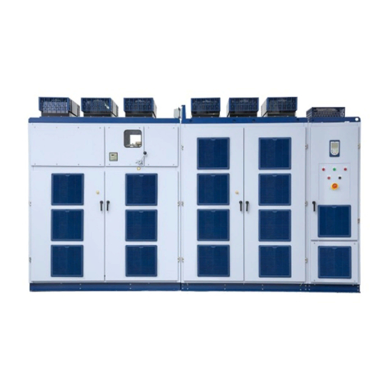
MVW3000. This manual must be used together with the User’s Manual. 3.1 ABOUT THE MANUAL This manual contains 7 chapters, which have a logical sequence for the user to program and operate the MVW3000: Chapter 2 SAFETY INSTRUCTIONS on page 2-1 . - Page 64 4-4. For models with rated voltage above 8000 V, contact WEG. Figure 3.1: General illustration of the MVW3000 panel (Frame B6) WARNING! It is very important to check that the inverter software version is the same as indicated on the first page of this manual.
-
Page 65: Hmi Operation
4 HMI OPERATION The HMI Interface (HMI - Human Machine Interface) provides a series of new resources to the medium voltage frequency inverter MVW3000. They are: Visualization: text and graphic visualization mode. Monitoring: up to 6 parameters can be monitored simultaneously on the screen. -
Page 66: Starting The Use Of The Hmi
4.2 STARTING THE USE OF THE HMI The HMI works as the communication master. When the panel is energized, the HMI performs a parameter initialization with the MVC4 board. During this process the firmware versions of the HMI and of the MVW3000 control boards are exhibited. -
Page 67: Hmi Basic Visualization Modes
Motor speed (rpm). Footer: Time. Function of the 2 softkeys. The various modules or visualization screens of the HMI can be classified in 6 different basic types: 1 parameter. 2 or 3 parameters. 4 to 6 parameters. Navigation: MVW3000 | 4-3... - Page 68 1800 rpm 200.0 1800 P0003: Motor curre: 200.0 A 60.0 Inv. Status: In Ref. P0005: Motor Frequ: 60.0 Hz Output Volt: 4160 V Trend 13:38 Menu Trend 13:38 Menu Trend 13:38 Menu Figure 4.4: Parameter monitoring modes. MVW3000 | 4-4...
-
Page 69: Structure Of The Menu
The Menu is composed by several access levels. The navigation through these levels is done by means of the softkeys [Exit] and [Select]. In order to select one group the key or the softkey [Select] can be used. MVW3000 | 4-5... -
Page 70: Parameter Edition
Menu Allows viewing of the MVW3000 reading variables. Status Diagnostics It allows viewing variables and events that may help diagnose problems or improve the MVW3000 operation. Configurations This menu allows the programming of all MVW3000 configuration parameters. In the navigation modes, a scrollbar appears at the HMI left side, with the purpose of helping the navigation by signalizing the relative position of the cursor regarding the total of possible groups/parameters. -
Page 71: Alphanumerical Edition
P0227 = 5 (Graphic HMI key). P0228 = 6 (Graphic HMI key). The automatic programming of the parameters described above may be done through the parameter P0491 “HMI commands configuration” (Menu → Configurations → HMI → Settings). MVW3000 | 4-7... -
Page 72: Configuring The Monitoring Mode Read-Only Parameters
The graphic function is accessed through the [Graphic] softkey, from the parameter monitoring mode. ✓ NOTE! For the [Graphic] softkey to be available, it is necessary that at least one read-only parameter be programmed for Graphic (Menu → Configurations → HMI → Graphic). MVW3000 | 4-8... -
Page 73: Alarms And Faults
4.5 ALARMS AND FAULTS 4.5.1 Alarms/Faults Screen When fault or alarm occurs in the MVW3000, HMI enters the error warning mode (refer to Figure 4.9 on page 4-10). The HMI stays in this error warning mode until the user selects [Exit]or error [Reset], through the correspondent softkeys. -
Page 74: Note Screen
Notes usually occur because of configuration errors of the HMI commands (generating Modbus errors) or because of attempts to command the inverter in not allowed situations (general enabling with the inverter in undervoltage or error). MVW3000 | 4-10... -
Page 75: Error Log
[+Info] option through the corresponding softkey (refer to Figure 4.11 on page 4-11). 0rpm Last Error A0110 Motor overtemperature alarm Date: 08/04/2015 Hour: 17:11 Status: Acceleration Ramp Exit 13:38 Figure 4.12: More information about the error MVW3000 | 4-11... -
Page 76: Help Function
Ratio of the input current CTs > It sets the the ratio of the current transformers used in the measurement of the input current. > Set according to the current transformer nameplate data. Exit 13:38 Figure 4.13: Help function visualization mode MVW3000 | 4-12... -
Page 77: Detailed Parameter Description
C6.4 Analog outputs Protections Functions C8.1 Bypass C8.2 Flying Start C8.3 Ride-Through C8.4 C8.5 Trace Communications Backup P0000 - Parameter access password Adjustable range: 0 to 999 Factory setting: Menu → Configurations → HMI → Password Acesso: MVW3000 | 5-1... - Page 78 0 = ‘Booting’ indicates that the control board is waiting for the initialization end. 1 = ‘Sub’ indicates that the inverter has insufficient voltage for operation (undervoltage), and it does not accept the enabling command (inverter waiting for the pre-charge/power energization command). MVW3000 | 5-2...
- Page 79 25 = ‘Fast Disab’ indicates fast disable (HG = off) mode (MVC3). 26 = ‘Sync OK’ indicates that the inverter is synchronized with the line. 27 = Not implanted in this software version. 28 = Not implanted in this software version. MVW3000 | 5-3...
- Page 80 Menu → Status → Measurements → Torque Acesso: Description: It indicates the torque value produced by the motor. It is calculated as follows: × 100 P0009 = rated Being: = Present motor torque current. Vector control mode: = Rated motor torque current. rated MVW3000 | 5-4...
- Page 81 5 relay outputs of the MVC4 control board through the letters A (Active) and I (Inactive), in the following order: DO1, DO2, RL1, RL2, RL3, RL4, RL5 Table 5.3: Digital outputs DO1 to RL5 status Description Bit 1 Bit 2 Bit 3 Bit 4 Bit 5 Bit 6 Bit 7 MVW3000 | 5-5...
- Page 82 It indicates the value of analog input AI5 of the MVC4 control board in percentage of full scale. The indicated values are obtained by means of addition of the offset and multiplication by the gain. See description of parameters P0721 to P0724. MVW3000 | 5-6...
- Page 83 The scale can be changed through P0528 and P0529. See the detailed description in Section 6.1 PID REGULATOR on page 6-1. ✓ NOTE! This parameter is only visible on the HMI when: the PID function is active, P0203 = 1 (PID regulator). MVW3000 | 5-7...
- Page 84 This value is kept even when the inverter is powered down. P0045 - HMI software version Menu → Status → Inverter → Software version Acesso: Description: It indicates the software version contained in the microcontroller memory located in the HMI . MVW3000 | 5-8...
- Page 85 DI5 - Enabling of the input protection Bit 11 DI4 - Circuit breaker OFF state Bit 12 DI3 - Circuit breaker ON state Bit 13 DI2 - Circuit breaker Ready Bit 14 DI1 - Power ON (Starts pre-charge) Bit 15 MVW3000 | 5-9...
- Page 86 It indicates the shaft position of the synchronous motor. The Graphic HMI shows the position in degrees between 0° and 360°. Resolution = 1.4°. ✓ NOTE! 8 most significant bits = number of turns. 8 least significant bits = position within the same turn. MVW3000 | 5-10...
- Page 87 2nd ramp function. Refer to parameters from P0265 to P0272. 24 V DIx - Open Run/Stop Time 24 V DIx - 2nd ramp Open Time P0102 P0103 P0100 P0101 Motor speed Time Figure 5.2: 2nd ramp MVW3000 | 5-11...
- Page 88 Menu → Configurations → Control Acesso: Description: It defines the external reference for the reactive current of the synchronous motor. For negative values, the reference of the reactive current will be capacitive. For positive values, it will be inductive. MVW3000 | 5-12...
- Page 89 The motor speed reference will adopt the value set in P0121 if P0221 = 0 (Key of service HMI) or P0222 = 0 (Key of service HMI). When P0120 = 1 (Active), the value of P0121 is kept in the last value set even de-energizing the inverter. Activation of JOG function: MVW3000 | 5-13...
- Page 90 P0129 = 1500 rpm P0130 = 1800 rpm P0131 = 1650 rpm Menu → Configurations → Control Acesso: Description: These parameters (P0124 to P0131) will only be displayed when P0221 = 8 and/or P0222 = 8 (Multispeed (P0124 to P0131)). MVW3000 | 5-14...
- Page 91 Time 1 (closed) 0 (open) 1 (closed) 0 (open) 1 (closed) 0 (open) Figure 5.5: Multispeed P0132 - Maximum overspeed level Adjustable range: 0 to 100 % Factory setting: 10 % Menu → Configurations → Control Acesso: MVW3000 | 5-15...
- Page 92 DETAILED PARAMETER DESCRIPTION Description: When the actual speed exceeds the value of P0134 + P0132 for over 20 ms, the MVW3000 will disable the PWM pulses and indicate fault F0112 (Motor Over Speed). The setting of P0132 is a percentage value of P0134.
- Page 93 (F0070, F0071 and F0072). The maximum value of increase for the output voltage is equal to 20 % of the rated voltage, in null frequency, when P0136 = 100. Setting 0 means inactive function. MVW3000 | 5-17...
- Page 94 This parameter is only visible on the HMI when: the control type is scalar, P0202 = 0, 1 or 2 (V/F control). P0137 - Addition on the automatic torque curve Adjustable range: 0 to 1000 Factory setting: Menu → Configurations → Control Acesso: MVW3000 | 5-18...
- Page 95 P0138 allows the user to set precisely the slip compensation on the MVW3000. Once P0138 is set, the inverter will keep the speed constant even with load variations by means of the automatic setting of voltage and frequency.
- Page 96 Description: It sets the time constant of the active current filter. It sets the response time of the slip compensation and automatic torque boost. See Figure 5.10 on page 5-19 and Figure 5.12 on page 5-19 . MVW3000 | 5-20...
- Page 97 Menu → Configurations → Control Acesso: Description: It defines the number of hours between the change of the ventilation set. ✓ NOTE! This parameter is only visible on the HMI when the redundant ventilation function is actived, P0140 > 0. MVW3000 | 5-21...
- Page 98 ✓ NOTE! This parameter can be changed only with the motor stopped. This parameter is only visible on the HMI when: the control type is adjustable scalar, P0202 = 2 (Adjustable V/F (refer to P0142 to P0146)). MVW3000 | 5-22...
- Page 99 (P0101 and/or P0103) must be increased. In case the line is permanently with overvoltage (DC link voltage > P0151) the inverter may not decelerate. Reduce the line voltage or increment P0151. MVW3000 | 5-23...
- Page 100 With the overload current curve adjustment it is possible to program an overload value that varies according to the inverter operation speed (factory default), improving the protection for self-ventilated motors, or to use a constant overload level for any speed applied to the motor (motor with separated ventilation). MVW3000 | 5-24...
- Page 101 0 to 100 % Factory setting: 80 % Menu → Configurations → Protections Acesso: Description: When the value of P0076 reaches the value given in this parameter, alarm A0046 (Motor Ixt function overload) is indicated on the HMI. MVW3000 | 5-25...
- Page 102 P0167 - Current regulator proportional gain P0168 - Current regulator Integral gain Adjustable range: P0167 = 0.000 to 9.999 Factory setting: P0167 = 0.080 P0168 = 0.1 to 999.9 P0168 = 12.3 Menu → Configurations → Control Acesso: MVW3000 | 5-26...
- Page 103 This parameter is only visible on the HMI when: the control type is scalar, P0202 = 0, 1 or 2 (V/F control). P0170 - Maximum reverse torque current P0171 - Maximum current of forward torque Adjustable range: 0 to 250 % Factory setting: 105 % Menu → Configurations → Protections Acesso: MVW3000 | 5-27...
- Page 104 This parameter is only visible on the HMI when: the control type is vector, P0202 = 3 (Sensorless Vector) or P0202 = 4 (Vector with Encoder). P0180 - Starting point of the field weakening Adjustable range: 0 to 120 % Factory setting: 85 % Menu → Configurations → Control Acesso: MVW3000 | 5-28...
- Page 105 When set to Active, it allows changing the contents of the parameters when P0000 is equal to the value of the password. Table 5.15: Password P0200 Function Inactive Active P0201 - Language selection Adjustable range: 0 to 4 Factory setting: Menu → Configurations → HMI → Language Acesso: Description: It defines the language of the Graphic HMI. MVW3000 | 5-29...
- Page 106 P0402 P0411 P0403 P0412 P0404 P0413 (not implemented) P0406 (not implemented) P0409 ... P04013 > 0 ? 1 = autogain P0408 Reset Figure 5.21: Guided start-up routine sequence Table 5.17 shows the summarized description of each parameter: MVW3000 | 5-30...
- Page 107 The values programmed at P0409 to P0413 must be different from zero; otherwise, the inverter will not leave the guided start-up routine. The configuration of this parameter must be done under the orientation of WEG technical assistance. Table 5.18: Control Type...
- Page 108 Parameters P0295 (Inverter rated current), P0296 (Inverter rated voltage), P0308 (Serial address) and P0201 (Lan- guage selection) will not be changed when P0204 = 5 (Load WEG 60 Hz: It reset all the parameters to the 60 Hz factory default values.).
- Page 109 Table 5.22: Motor phase loss detection P0209 Function Inactive Active ✓ NOTE! This parameter can be changed only with the motor stopped. MVW3000 | 5-33...
- Page 110 P0214 - Line phase loss detection Adjustable range: 0 to 1 Factory setting: Menu → Configurations → Protections Acesso: Description: Line phase loss detection. MVW3000 | 5-34...
- Page 111 Serial (LOCAL Default) Serial (REMOTE Default) Fieldbus (LOCAL Default) Fieldbus (REMOTE Default) LOCAL PLC REMOTE PLC Graphic HMI key (LOCAL Default) Graphic HMI key (REMOTE Default) ✓ NOTE! This parameter can be changed only with the motor stopped. MVW3000 | 5-35...
- Page 112 P0223 - Forward/Reverse Selection LOCAL Situation Adjustable range: 0 to 13 Factory setting: Menu → Configurations → Commands → Local Acesso: Description: It defines the origin of the forward/reverse command and the direction used in LOCAL situation. MVW3000 | 5-36...
- Page 113 This parameter can be changed only with the motor stopped. P0225 - Selection of JOG Source LOCAL Situation Adjustable range: 0 to 6 Factory setting: Menu → Configurations → Commands → Local Acesso: Description: It defines the origin of the JOG command in the LOCAL situation. MVW3000 | 5-37...
- Page 114 Graphic HMI key (Reverse) ✓ NOTE! This parameter can be changed only with the motor stopped. P0227 - Start/Stop Selection REMOTE Situation Adjustable range: 0 to 5 Factory setting: Menu → Configurations → Commands → Remote Acesso: MVW3000 | 5-38...
- Page 115 DIRECTION OF ROTATION (P0223) (P0220) LOCAL/REMOTE RUN/STOP SELECTION (P0224) REFERENCE (P0225) LOCAL REFERENCE REFERENCE REFERENCE REMOTE COMMANDS LOCAL COMMANDS COMMANDS COMMANDS REMOTE REMOTE REFERENCE (P0222) DIRECTION OF ROTATION (P0226) RUN/STOP (P0227) (P0228) Figure 5.23: LOCAL/REMOTE situation block diagram MVW3000 | 5-39...
- Page 116 JOG + P0122 Direction of rotation P0102, P0103 JOG - P0123 P0134 = Maximum ref. P0133 = Minimum ref. P0163 P0164 P0134 2nd Ramp Total reference Read-only parameters P0133 P0001 P0002 P0005 P0133 P0100, P0101 Reference P0134 Commands and Reference limits reference Fast stop Run/Stop...
- Page 117 P0146 P0145 Speed Reference = Output current Transf. P0137 P0138 Automatic torque boost Slip active Speed Speed compensation P0139 P0169 = Maximum output current Run/Stop P0169 Figure 5.25: Block diagram of scalar control with sinusoidal output filter MVW3000 | 5-41...
- Page 118 AI2, AI3 / P0237, P0241 = 2 max. torque current Speed regulator Current regulator INVERTER Usq* (Speed/torque control) Total reference Usd* Gp = P0161 MaxtH = P0169 with encoder Gp = P0167 P0202 Ti = P0162 MaxtAH = P0170 Ti = P0168 sensorless Flux regulator Torque current...
- Page 119 When the “DISABLE GENERAL” stop mode is programmed, only drive the motor if it is stopped or set the necessary time for which the inverter is disabled (COAST) in P0725 to ensure the motor stop, or enable the Flystart function. Table 5.35: Stop Selection P0232 Function Run/Stop General disable MVW3000 | 5-43...
- Page 120 If the analog input AI2 or AI4 is programmed for (-10 to +10) V (P0246 = 4), curves identical to those of the Figure 5.28 on page 5-44, only when AI2 or AI4 is negative will the direction of rotation be inverted. MVW3000 | 5-44...
- Page 121 Table 5.37: AI1 Signal Type P0235 Function (0 to 10) V/(0 to 20) mA (4 to 20) mA (10 to 0) V/(20 to 0) mA (20 to 4) mA ✓ NOTE! This parameter can be changed only with the motor stopped. MVW3000 | 5-45...
- Page 122 Example: AI2 = 5 V, OFFSET = -70 % and Gain = 1.00 (-70) × 10 V) × 1 = -2 V AI2’ = (5 + AI2’ = -2 V, meaning that the motor will run in reverse direction with a speed reference absolute value equal to 2 V. MVW3000 | 5-46...
- Page 123 Factory setting: 0.0 % Menu → Configurations → I/O → Analog inputs Acesso: Description: Refer to P0238. P0241 - AI3 signal function Adjustable range: 0 to 3 Factory setting: Menu → Configurations → I/O → Analog inputs Acesso: MVW3000 | 5-47...
- Page 124 Table 5.41: AI3 Signal Type P0243 Function (0 to 10) V/(0 to 20) mA (4 to 20) mA (10 to 0) V/(20 to 0) mA (20 to 4) mA ✓ NOTE! This parameter can be changed only with the motor stopped. MVW3000 | 5-48...
- Page 125 This parameter can be changed only with the motor stopped. P0247 - Analog input AI4 offset (bipolar EBA board) Adjustable range: -100.0 to 100.0 % Factory setting: 0.0 % Menu → Configurations → I/O → Analog inputs Acesso: Description: Refer to P0234. MVW3000 | 5-49...
- Page 126 Menu → Configurations → I/O → Analog outputs Acesso: Description: It sets the gain of analog output AO2. For P0254 = 1.000 the output value of AO2 is set according to the description “analog output indication scale” in P0262. MVW3000 | 5-50...
- Page 127 For values in the factory default (P0259 = 2 and P0260 = 1.000) AO5 = 20 mA when Actual Speed = Maximum speed reference (P0134). See Table 5.43 on page 5-52 for further details related to the function of analog outputs. MVW3000 | 5-51...
- Page 128 Not used The same as the one of 11 a 11 a 11 a 11 a 11 a 11 a Trace channel 1 to 8 the chosen parameter Inverter temperature 200 °C Output voltage 1 x P0296 MVW3000 | 5-52...
- Page 129 PID Process Variable: full scale = 1,0 x P0528. – PID reference: full scale = 1,0 x P0528. – Inverter temperature = 200 °C. √ – Output power: full scale = 2.0 x P0295 x P0296 x MVW3000 | 5-53...
- Page 130 ‘LOCAL/REMOTE’ = 0 V/24 V in the digital input respectively. – DI8 digital input is linked to the input for ‘Motor Thermistor’ (PTC) present on the EBA/EBB optional cards, as described in Table 5.44 on page 5-56 MVW3000 | 5-54...
- Page 131 P0279 and/or P0280 = 29 (Timer). The ‘Ventilation OK’ function generates an inverter ventilation fault (F0048). +24 V RL2/ P0283/ P0284/ P0283/ P0284/ P0285 P0286 P0285 P0286 Figure 5.34: RL2 and RL3 timer function operation MVW3000 | 5-55...
- Page 132 Motor thermistor Parameterization disabling Load user 1/2 RL2 timer RL3 timer No motor fault No motor alarm No alarm in the redundant ventilation set A No alarm in the redundant ventilation set B Initiates synchronous transfer Ventilation OK MVW3000 | 5-56...
- Page 133 24 V DIx - Open Run/Stop Time Motor decelerates Motor speed with null ramp 24 V Time DIx - 2nd ramp Open Time 24 V P0102 P0103 P0100 P0101 DIx - Fast stop Open Motor speed Time Time MVW3000 | 5-57...
- Page 134 DETAILED PARAMETER DESCRIPTION g) JOG Speed JOG (P0122) Acceleration ramp Motor speed Deceleration ramp Time 24 V Run/Stop Open Time 24 V DIx - JOG Open Time 24 V General enable Open Time MVW3000 | 5-58...
- Page 135 24 V Open Time 24 V Open DIx - Stop Time Motor speed Time k) FORWARD RUN/REVERSE RUN 24 V DIx - Forward Open Time 24 V DIx - Reverse Open Time Motor Clockwise speed Time Counterclockwise MVW3000 | 5-59...
- Page 136 Example: ‘Is > Ix’: when Is > Ix, then DOx = saturated transistor and/or RLx = relay with the coil energized. When Is = Ix then DOx = open transistor and/or RLx = relay with the coil not energized. MVW3000 | 5-60...
- Page 137 VPx = P0533 (Process variable X value) - It is a reference point of the process variable selected by the user. – VPy = P0534 (Process variable Y value) - It is a reference point of the process variable selected by the user. – Nt = Total Reference (refer to Figure 5.24 on page 5-40). MVW3000 | 5-61...
- Page 138 N > Nx b) N < Nx Nx (P0288) Ny (P0289) Time Time Relay/ Relay/ Transistor Transistor Time Time c) N = N* d) Is > Ix Ix (P0290) Time Time Relay/ Relay/ Transistor Transistor Time Time MVW3000 | 5-62...
- Page 139 P0291 Ref. 2 mA Time Time Relay/ Relay/ Transistor Transistor Time Time k) Process variable X > VPx l) Pre-charge OK DC Link Pre-charge Process level Variable VPx (P0533) Time Time Relay/ Relay/ Transistor Transistor Time Time MVW3000 | 5-63...
- Page 140 Menu → Configurations → Control Acesso: Description: Used in the digital and relay output functions: Is > Ix and Is < Ix. P0291 - Zero Speed Zone Adjustable range: 1 to 100 % Factory setting: Menu → Configurations → Control Acesso: MVW3000 | 5-64...
- Page 141 310 A 340 A 400 A 450 A 500 A 550 A 600 A 650 A 700 A 750 A 800 A 850 A 900 A ✓ NOTE! This parameter can be changed only with the motor stopped. MVW3000 | 5-65...
- Page 142 It avoids permanent motor operation at speeds in which, for instance, the mechanical system enters into resonance causing high vibration or noise levels. The passage through the skipped range (2 x P0306) occurs through the acceleration and deceleration ramps. The function does not operate properly if two bands of skipped speed overlap. MVW3000 | 5-66...
- Page 143 1 to 6 = define the Fieldbus standard to be used (Profibus DP or DeviceNet) and the number of variables to be exchanged with the master. It is only applicable for the Profibus DP or DeviceNet optional kits. For P0309 = 10, refer to the DeviceNet Drive Profile Guide. MVW3000 | 5-67...
- Page 144 It defines the inverter behavior when the serial communication is inactive (causing A0128), when the physical connection with the Fieldbus network master is interrupted (causing error A0129), when the Fieldbus board is inactive (causing error A0130) or when the communication between MVC3 and MVC4 boards is interrupted. MVW3000 | 5-68...
- Page 145 The module serial configuration must be set as follows: Baudrate: 2400 bps Slave address: 1 Parity: even Stop bit: 1 Table 5.52: Function of the MVC3 SCI1 serial channel P0315 Function Service HMI Modbus serial for Tecsystem module Modbus Serial for Pextron module MVW3000 | 5-69...
- Page 146 P0331. Refer to the Figure 5.39 on page 5-71. The Flying Start function does not work when P0202 = 3 or 4. During the Ride-Through, the input cubicle is opened and the pre-charge system is activated. MVW3000 | 5-70...
- Page 147 P0137) This gain is added when P0202 = 0, 1 or 2. See Figure 5.7 on page 5-18 to Figure 5.9 on page 5-18 . ✓ NOTE! The motor output voltage (P0400) must be lower than or equal to the inverter voltage (P0296). MVW3000 | 5-71...
- Page 148 100 to 9999 PPR Factory setting: 1024 PPR Menu → Configurations → Nominal data → Motor Acesso: Description: Program the number of pulses per revolution (ppr) of the used incremental encoder when P0202 = 4 (Vector with Encoder). MVW3000 | 5-72...
- Page 149 Vector) or P0202 = 4 (Vector with Encoder). P0409 - Motor stator resistance Rs Adjustable range: 0.000 to 9.999 Ω Factory setting: 0.000 Ω Menu → Configurations → Nominal data → Motor Acesso: Description: It is the value of the motor stator resistance. MVW3000 | 5-73...
- Page 150 Menu → Configurations → Nominal data → Motor Acesso: Description: It is the mechanical time constant. ✓ NOTE! This parameter is only visible on the HMI when: the control type is vector, P0202 = 3 (Sensorless Vector) or P0202 = 4 (Vector with Encoder). MVW3000 | 5-74...
- Page 151 This parameter is only visible on the HMI when: P0950 = 1 (Synchronous motor with brushes). This parameter is only visible on the HMI when: the control type is vector, P0202 = 3 (Sensorless Vector) or P0202 = 4 (Vector with Encoder). MVW3000 | 5-75...
- Page 152 This parameter is only visible on the HMI when: the control type is vector, P0202 = 3 (Sensorless Vector) or P0202 = 4 (Vector with Encoder). P0431 - Number of motor poles Adjustable range: 2 to 64 Factory setting: Menu → Configurations → Nominal data → Motor Acesso: Description: Number of motor poles. MVW3000 | 5-76...
- Page 153 0.000 to 9.999 Factory setting: 0.034 Menu → Configurations → Control Acesso: Description: Parameter used by the regulator to control the currents. μ Current regulator P0438, P0439, P0440, P0441 Figure 5.42: Complete model of the stator flux MVW3000 | 5-77...
- Page 154 This parameter is only visible on the HMI when: P0950 = 1 (Synchronous motor with brushes). This parameter is only visible on the HMI when: the control type is vector, P0202 = 3 (Sensorless Vector) or P0202 = 4 (Vector with Encoder). MVW3000 | 5-78...
- Page 155 Menu → Configurations → Protections Acesso: Description: Minimum limit in PU of P0462 used in the control of the field current reference, see Section 5.2 FIELD EXCI- TATION SET (DC WITH BRUSHES) on page 5-3 of the User’s Manual. MVW3000 | 5-79...
- Page 156 When encoder is used, this parameter must be set to 0 Hz, disabling the soft-start without encoder function. For further information, contact WEG Technical Assistance. WARNING! For encoder setting: Set parameter P0452 (Field input frequency) to 0 Hz.
- Page 157 Figure 5.43: Typical saturation curve and mathematical approximations used by the inverter for flux control ✓ NOTE! For further information, contact WEG Technical Assistance. ✓ NOTE! This parameter is only visible on the HMI when: P0950 = 1 (Synchronous motor with brushes).
- Page 158 This parameter is only visible on the HMI when: P0950 = 1 (Synchronous motor with brushes). This parameter is only visible on the HMI when: the control type is vector, P0202 = 3 (Sensorless Vector) or P0202 = 4 (Vector with Encoder). MVW3000 | 5-82...
- Page 159 P0505 - Read-only parameter 6 selection Adjustable range: 0 to 9 Factory setting: P0500 = 2 P0501 = 0 P0502 = 0 P0503 = 0 P0504 = 0 P0505 = 0 Menu → Configurations → HMI → Main screen Acesso: MVW3000 | 5-83...
- Page 160 P0517 - Full scale of online graphic 2 P0518 - Full scale of online graphic 3 P0519 - Full scale of online graphic 4 Adjustable range: 0 to 200 % Factory setting: 100 % Menu → Configurations → HMI → Graphic Acesso: MVW3000 | 5-84...
- Page 161 fluid into the reservoir, the action will be direct. In case of level control, the integral gain adjustment will depend on the time required for the reservoir to pass from the minimum acceptable to the desired level, in the following conditions: MVW3000 | 5-85...
- Page 162 This parameter is only visible on the HMI when: the PID function is active, P0203 = 1 (PID regulator). This parameter can be changed only with the motor stopped. P0525 - PID regulator setpoint Adjustable range: 0.0 to 100.0 % Factory setting: 0.0 % Menu → Configurations → Functions → PID Acesso: MVW3000 | 5-86...
- Page 163 Example 2 - Reverse: The inverter drives a fan responsible for cooling a cooling tower using the PID to control the temperature. In order to increase the temperature (process variable), it is necessary to decrease the ventilation by decreasing the motor speed. MVW3000 | 5-87...
- Page 164 P0533 = 0.0 to 100.0 % Factory setting: P0533 = 90.0 % P0534 = 0.0 to 100.0 % P0534 = 10.0 % P0535 = 0 to 100 % P0535 = 0 % Menu → Configurations → Functions → PID Acesso: MVW3000 | 5-88...
- Page 165 It determines the end actuation frequency of the manual torque boost. For further information, refer to parameter P0136 (Addition on the manual torque curve (IxR)). The frequency is determined by the equation below: P0622 × P0403 P0622 (Hz) = 8192 MVW3000 | 5-89...
- Page 166 Menu → Configurations → Control Acesso: Description: Parameter used to compensate the phase error between the voltage the inverter uses as reference for syn- chronism and the actual voltage in the point where the transfer will occur. MVW3000 | 5-90...
- Page 167 10 V = +200 % * * Torque percentage regarding the motor torque. ✓ NOTE! For other options not described in Table 5.68 on page 5-94,contact WEG Technical Assistance. P0653 - Analog output gain AO1 MVC3 Adjustable range: 0.000 to 9.999 Factory setting: 1.000 Menu →...
- Page 168 10 V = +200 % * * Torque percentage regarding the motor torque. ✓ NOTE! For other options not described in Table 5.68 on page 5-94,contact WEG Technical Assistance. P0655 - Analog output gain AO2 MVC3 Adjustable range: 0.000 to 9.999 Factory setting: 1.000 Menu →...
- Page 169 10 V = +200 % * * Torque percentage regarding the motor torque. ✓ NOTE! For other options not described in Table 5.68 on page 5-94,contact WEG Technical Assistance. P0657 - Analog output gain AO3 MVC3 Adjustable range: 0.000 to 9.999 Factory setting: 1.000 Menu →...
- Page 170 10 V = +200 % * * Torque percentage regarding the motor torque. ✓ NOTE! For other options not described in Table 5.68 on page 5-94,contact WEG Technical Assistance. P0659 - Analog output gain AO4 MVC3 Adjustable range: 0.000 to 9.999 Factory setting: 1.000 Menu →...
- Page 171 This parameter can be changed only with the motor stopped. P0724 - Analog input AI5 offset (bipolar isolated MVC4 board) Adjustable range: 0.0 to 100.0 % Factory setting: 0.0 % Menu → Configurations → I/O → Analog inputs Acesso: MVW3000 | 5-95...
- Page 172 It sets the offset of analog input AI1 of the MVC3 board. Refer to P0234 (Analog input AI1 gain (unipolar MVC4 board)). P0744 - Function of analog input AI2 MVC3 Adjustable range: 0 to 1 Factory setting: Menu → Configurations → I/O → Analog inputs Acesso: MVW3000 | 5-96...
- Page 173 Brushless synchronous motor ✓ NOTE! This parameter can be changed only with the motor stopped. P0957 - Direction of rotation of the speed sensor Adjustable range: 0 to 1 Factory setting: Menu → Configurations → Control Acesso: MVW3000 | 5-97...
- Page 174 P1022 - DC link voltage of cell V11 P1023 - DC link voltage of cell V12 Menu → Status → Measurements → Voltage Acesso: Description: It indicates the DC link voltage, in volts, of the respective cell. MVW3000 | 5-98...
- Page 175 P1071 - Temperature on the power module of cell V10 P1072 - Temperature on the power module of cell V11 P1073 - Temperature on the power module of cell V12 Menu → Status → Measurements → Temperature Acesso: MVW3000 | 5-99...
- Page 176 Menu → Status → Measurements → Power Acesso: Description: It indicates the cosine of the angle between the voltage and current at the inverter input. The input power factor is calculated according to the equation: P1140 P1138 = P1136 MVW3000 | 5-100...
- Page 177 In P1137 you can see the angle between voltage and current in the inverter input. The reactive power in the input is calculated according to the equation below: √ 3 × reactive current × P1137 P1141 = Being: P1137 = Inverter input line voltage. MVW3000 | 5-101...
- Page 178 P1360 - Temperature on the board of cell U11 P1361 - Temperature on the board of cell U12 Menu → Status → Measurements → Temperature Acesso: Description: It indicates the temperature on the control board, in degrees Celsius (°C), of the respective cell. MVW3000 | 5-102...
- Page 179 If P1500 = 1, the time to close the bypass relay is half the Flying Start dead time (P0332). The maximum number of bypassed cells after a manageable fault occurs is limited by parameter P1502. Faults manageable by the automatic bypass function: MVW3000 | 5-103...
- Page 180 P1502 - Limit of bypassed cells per phase Adjustable range: 0 to 12 Factory setting: Menu → Configurations → Functions → Bypass Acesso: Description: It defines the maximum number of cells per phase may be placed in automatic bypass. MVW3000 | 5-104...
- Page 181 Menu → Configurations → Nominal data → Inverter Acesso: Description: It sets the modification occurred on the voltage supplied for the inverter cells. Set it according to the input transformer tap connections. ✓ NOTE! This parameter can be changed only with the motor stopped. MVW3000 | 5-105...
- Page 182 It sets the ratio of the current transformers used in the measurement of the inverter input current. Set it according to the current transformer nameplate data. Notes: It is recommended that the CT primary current be greater than or equal to the transformer primary rated current. MVW3000 | 5-106...
- Page 183 P1559 - Transformer 3 CT Ratio Adjustable range: 50 to 3000 Factory setting: Menu → Configurations → Nominal data → Inverter Acesso: Description: It sets the ratio of the current transformers used in the measurement of the inverter input current. MVW3000 | 5-107...
- Page 184 Set it according to the nameplate data of the transformer used. ✓ NOTE! This parameter can be changed only with the motor stopped. This parameter is only visible on the HMI when: P1893 (Transformer at the input) = 3 transform- ers. MVW3000 | 5-108...
- Page 185 Table 5.77: Bypass of the cell U12 P1711 Function Disable Mechanical bypass cell Manual activation of the bypass relay Automatic bypass after a manageable fault Automatic bypass by parallel association MVW3000 | 5-109...
- Page 186 Table 5.78: Bypass of the cell V12 P1723 Function Disable Mechanical bypass cell Manual activation of the bypass relay Automatic bypass after a manageable fault Automatic bypass by parallel association ✓ NOTE! This parameter can be changed only with the motor stopped. MVW3000 | 5-110...
- Page 187 This parameter can be changed only with the motor stopped. P1739 - RL8 Function MVC3 Adjustable range: 0 to 2 Factory setting: Menu → Configurations → I/O → Digital outputs Acesso: Description: Digital output state can be monitored on parameter P0071. MVW3000 | 5-111...
- Page 188 Acesso: Description: Sets the number of transformers at the inverter input. Table 5.82: Transformer at the input P1893 Function 1 transformer 2 transformers 3 transformers ✓ NOTE! This parameter can be changed only with the motor stopped. MVW3000 | 5-112...
-
Page 189: Special Functions
6 SPECIAL FUNCTIONS 6.1 PID REGULATOR The MVW3000 has the PID regulator function, which can be used to control a closed loop process. That function consists of a controller with proportional, integral and derivative gain, superposed to the normal MVW3000 speed control. - Page 190 If the setpoint is defined by P0525 (P0221 or P0222 = 0), and the system is changed from manual to automatic, then P0525 is automatically adjusted with the P0040 value. In this case the transition from manual to automatic is smooth (there is no sudden speed variation). MVW3000 | 6-2...
- Page 191 Note 1: P0221/P0222 = 0 (Setpoint by keys) Note 2: P0221/P0222 = 1 to 11 (Setpoint via analog inputs, multispeed, serial, fieldbus, PLC) Setpoint Definition (process variable reference) Enable P0525 Note 1 Inverter speed reference Setpoint Note 2 P0523 Manual (DIx open) P0527 P0040...
- Page 192 SPECIAL FUNCTIONS MVW3000 | 6-4...
-
Page 193: Diagnostics And Troubleshooting
Mains Unbalance/ Phase Loss value. Auto-reset. It resets automatically after the cause is eliminated. DIx. Networks. Manual ( /RESET key). Synchronism function could not synchronize suc- A0008 cessfully. Timeout in the synchronism with the input line during synchronous transfer MVW3000 | 7-1... - Page 194 DIAGNOSTICS AND TROUBLESHOOTING Fault/alarm Reset Possible causes Contact WEG Service Center. Incorrect operation of the input cubicle. F0009 Defective input cubicle. Incorrect status of the input cubicle Wiring of the DI3 input (XC7:3) and/or action of the DI4 input (XC7:4) of PIC card defective.
- Page 195 Wiring of DI1 input of PIC board (XC7:1) open (no Auto-reset. cubicle feedback of +24 V). DIx. Networks. Contact WEG Service Center. Electrical arcing detection by the panel sensors. F0044 Electrical arcing detection fault Automatic eliminated when overload Setting of P0156, P0157 and P0158 too low for...
- Page 196 Short circuit in the ventilation system. A0094 eliminated. Fan locked. Cooling system supply fault Circuit breakers that feed the inverter ventilation system open. Wiring of DI10 input of PIC board (XC7:15) open (no feedback of +24 V). MVW3000 | 7-4...
- Page 197 firmware version of the Help not recorded/Incompatible graphic HMI. HMI version Contact WEG Service Center. Offset of the output current measurements out of F0099 the acceptable range. Invalid output current offset Defect on the output current measurement cir- cuit.
- Page 198 Manual ( /RESET key). time set at P0332 + P0333. Timeout in Ride-through state Inverter input voltage below 80 %. Auto-reset. Waiting Line Undervoltage in the mains supply. DIx. Incorrect setting of the transformer primary taps; Networks. MVW3000 | 7-6...
- Page 199 12.5 % of the inverter rated current. Networks. Sensors measuring the output current are defec- tive. Contact WEG Service Center. Fault on the feedback circuit of the line voltage F0320 between phases A and B at the inverter input. Vab measurement feedback fault Fiber optic Vab not connected, inverted or defec- tive.
- Page 200 DIAGNOSTICS AND TROUBLESHOOTING Fault/alarm Reset Possible causes Contact WEG Service Center. Fault on the feedback circuit of the voltage be- F0327 tween the motor virtual neutral and the system Vn_gnd measurement feedback ground. fault Fiber optic N_GND not connected, inverted or defective.
- Page 201 PT100 accessory connectors disconnected. Fault in the temperature sensor of Temperature channel active without a sensor Auto-reset. the thermal protection relay CH6 connected to the PT100 accessory. It resets automatically after the cause is eliminated. DIx. Networks. MVW3000 | 7-9...
- Page 202 CH7 DIx. Networks. Power-on. Temperature above the fault level set on the ther- F0375 Manual ( /RESET key). mal protection relay and P0315 > 0. Overtemperature detected by the Auto-reset. thermal protection relay CH8 DIx. Networks. MVW3000 | 7-10...
- Page 203 Temperature above the alarm level set on the A0383 Manual ( /RESET key). thermal protection relay and P0315 > 0. Overtemperature detected by the Auto-reset. thermal protection relay CH8 It resets automatically after the cause is eliminated. DIx. Networks. MVW3000 | 7-11...
- Page 204 Auto-reset. module Fans locked or defective. DIx. Air input filters blocked. Networks. Contact WEG Service Center. Cell temperature measurement sensor defective. F0404 Cell temperature sensor disconnected. Defective temperature sensor or Temperature on the cell heatsink below -10 °C. undertemperature on cell U1 IGBT Contact WEG Service Center.
- Page 205 DIAGNOSTICS AND TROUBLESHOOTING Fault/alarm Reset Possible causes Contact WEG Service Center. Voltages of the internal electronic circuits of the F0411 cell out of the operation level. Cell U1 electronics power supply Defect on the cell power supply. Contact WEG Service Center.
- Page 206 DIAGNOSTICS AND TROUBLESHOOTING Fault/alarm Reset Possible causes Contact WEG Service Center. Short circuit at the inverter output. F0430 Trigger board of the IGBTs of the cell phase arm Cell U2 phase IGBT disconnected. IGBTs of the cell phase arm operating out of the saturation region.
- Page 207 Auto-reset. module Fans locked or defective. DIx. Air input filters blocked. Networks. Contact WEG Service Center. Cell temperature measurement sensor defective. F0454 Cell temperature sensor disconnected. Defective temperature sensor or Temperature on the cell heatsink below -10 °C. undertemperature on cell U3 IGBT Contact WEG Service Center.
- Page 208 DIAGNOSTICS AND TROUBLESHOOTING Fault/alarm Reset Possible causes Contact WEG Service Center. Voltages of the internal electronic circuits of the F0461 cell out of the operation level. Cell U3 electronics power supply Defect on the cell power supply. Contact WEG Service Center.
- Page 209 DIAGNOSTICS AND TROUBLESHOOTING Fault/alarm Reset Possible causes Contact WEG Service Center. Short circuit at the inverter output. F0480 Trigger board of the IGBTs of the cell phase arm Cell U4 phase IGBT disconnected. IGBTs of the cell phase arm operating out of the saturation region.
- Page 210 Auto-reset. module Fans locked or defective. DIx. Air input filters blocked. Networks. Contact WEG Service Center. Cell temperature measurement sensor defective. F0504 Cell temperature sensor disconnected. Defective temperature sensor or Temperature on the cell heatsink below -10 °C. undertemperature on cell U5 IGBT Contact WEG Service Center.
- Page 211 DIAGNOSTICS AND TROUBLESHOOTING Fault/alarm Reset Possible causes Contact WEG Service Center. Voltages of the internal electronic circuits of the F0511 cell out of the operation level. Cell U5 electronics power supply Defect on the cell power supply. Contact WEG Service Center.
- Page 212 DIAGNOSTICS AND TROUBLESHOOTING Fault/alarm Reset Possible causes Contact WEG Service Center. Short circuit at the inverter output. F0530 Trigger board of the IGBTs of the cell phase arm Cell U6 phase IGBT disconnected. IGBTs of the cell phase arm operating out of the saturation region.
- Page 213 Auto-reset. module Fans locked or defective. DIx. Air input filters blocked. Networks. Contact WEG Service Center. Cell temperature measurement sensor defective. F0554 Cell temperature sensor disconnected. Defective temperature sensor or Temperature on the cell heatsink below -10 °C. undertemperature on cell U7 IGBT Contact WEG Service Center.
- Page 214 DIAGNOSTICS AND TROUBLESHOOTING Fault/alarm Reset Possible causes Contact WEG Service Center. Voltages of the internal electronic circuits of the F0561 cell out of the operation level. Cell U7 electronics power supply Defect on the cell power supply. Contact WEG Service Center.
- Page 215 DIAGNOSTICS AND TROUBLESHOOTING Fault/alarm Reset Possible causes Contact WEG Service Center. Short circuit at the inverter output. F0580 Trigger board of the IGBTs of the cell phase arm Cell U8 phase IGBT disconnected. IGBTs of the cell phase arm operating out of the saturation region.
- Page 216 Auto-reset. module Fans locked or defective. DIx. Air input filters blocked. Networks. Contact WEG Service Center. Cell temperature measurement sensor defective. F0604 Cell temperature sensor disconnected. Defective temperature sensor or Temperature on the cell heatsink below -10 °C. undertemperature on cell V1 IGBT Contact WEG Service Center.
- Page 217 DIAGNOSTICS AND TROUBLESHOOTING Fault/alarm Reset Possible causes Contact WEG Service Center. Voltages of the internal electronic circuits of the F0611 cell out of the operation level. Cell V1 electronics power supply Defect on the cell power supply. Contact WEG Service Center.
- Page 218 DIAGNOSTICS AND TROUBLESHOOTING Fault/alarm Reset Possible causes Contact WEG Service Center. Short circuit at the inverter output. F0630 Trigger board of the IGBTs of the cell phase arm Cell V2 phase IGBT disconnected. IGBTs of the cell phase arm operating out of the saturation region.
- Page 219 Auto-reset. module Fans locked or defective. DIx. Air input filters blocked. Networks. Contact WEG Service Center. Cell temperature measurement sensor defective. F0654 Cell temperature sensor disconnected. Defective temperature sensor or Temperature on the cell heatsink below -10 °C. undertemperature on cell V3 IGBT Contact WEG Service Center.
- Page 220 DIAGNOSTICS AND TROUBLESHOOTING Fault/alarm Reset Possible causes Contact WEG Service Center. Voltages of the internal electronic circuits of the F0661 cell out of the operation level. Cell V3 electronics power supply Defect on the cell power supply. Contact WEG Service Center.
- Page 221 DIAGNOSTICS AND TROUBLESHOOTING Fault/alarm Reset Possible causes Contact WEG Service Center. Short circuit at the inverter output. F0680 Trigger board of the IGBTs of the cell phase arm Cell V4 phase IGBT disconnected. IGBTs of the cell phase arm operating out of the saturation region.
- Page 222 Auto-reset. module Fans locked or defective. DIx. Air input filters blocked. Networks. Contact WEG Service Center. Cell temperature measurement sensor defective. F0704 Cell temperature sensor disconnected. Defective temperature sensor or Temperature on the cell heatsink below -10 °C. undertemperature on cell V5 IGBT Contact WEG Service Center.
- Page 223 DIAGNOSTICS AND TROUBLESHOOTING Fault/alarm Reset Possible causes Contact WEG Service Center. Voltages of the internal electronic circuits of the F0711 cell out of the operation level. Cell V5 electronics power supply Defect on the cell power supply. Contact WEG Service Center.
- Page 224 DIAGNOSTICS AND TROUBLESHOOTING Fault/alarm Reset Possible causes Contact WEG Service Center. Short circuit at the inverter output. F0730 Trigger board of the IGBTs of the cell phase arm Cell V6 phase IGBT disconnected. IGBTs of the cell phase arm operating out of the saturation region.
- Page 225 Auto-reset. module Fans locked or defective. DIx. Air input filters blocked. Networks. Contact WEG Service Center. Cell temperature measurement sensor defective. F0754 Cell temperature sensor disconnected. Defective temperature sensor or Temperature on the cell heatsink below -10 °C. undertemperature on cell V7 IGBT Contact WEG Service Center.
- Page 226 DIAGNOSTICS AND TROUBLESHOOTING Fault/alarm Reset Possible causes Contact WEG Service Center. Voltages of the internal electronic circuits of the F0761 cell out of the operation level. Cell V7 electronics power supply Defect on the cell power supply. Contact WEG Service Center.
- Page 227 DIAGNOSTICS AND TROUBLESHOOTING Fault/alarm Reset Possible causes Contact WEG Service Center. Short circuit at the inverter output. F0780 Trigger board of the IGBTs of the cell phase arm Cell V8 phase IGBT disconnected. IGBTs of the cell phase arm operating out of the saturation region.
- Page 228 Auto-reset. module Fans locked or defective. DIx. Air input filters blocked. Networks. Contact WEG Service Center. Cell temperature measurement sensor defective. F0804 Cell temperature sensor disconnected. Defective temperature sensor or Temperature on the cell heatsink below -10 °C. undertemperature on cell W1 IGBT Contact WEG Service Center.
- Page 229 DIAGNOSTICS AND TROUBLESHOOTING Fault/alarm Reset Possible causes Contact WEG Service Center. Voltages of the internal electronic circuits of the F0811 cell out of the operation level. Cell W1 electronics power supply Defect on the cell power supply. Contact WEG Service Center.
- Page 230 DIAGNOSTICS AND TROUBLESHOOTING Fault/alarm Reset Possible causes Contact WEG Service Center. Short circuit at the inverter output. F0830 Trigger board of the IGBTs of the cell phase arm Cell W2 phase IGBT disconnected. IGBTs of the cell phase arm operating out of the saturation region.
- Page 231 Auto-reset. module Fans locked or defective. DIx. Air input filters blocked. Networks. Contact WEG Service Center. Cell temperature measurement sensor defective. F0854 Cell temperature sensor disconnected. Defective temperature sensor or Temperature on the cell heatsink below -10 °C. undertemperature on cell W3 IGBT Contact WEG Service Center.
- Page 232 DIAGNOSTICS AND TROUBLESHOOTING Fault/alarm Reset Possible causes Contact WEG Service Center. Voltages of the internal electronic circuits of the F0861 cell out of the operation level. Cell W3 electronics power supply Defect on the cell power supply. Contact WEG Service Center.
- Page 233 DIAGNOSTICS AND TROUBLESHOOTING Fault/alarm Reset Possible causes Contact WEG Service Center. Short circuit at the inverter output. F0880 Trigger board of the IGBTs of the cell phase arm Cell W4 phase IGBT disconnected. IGBTs of the cell phase arm operating out of the saturation region.
- Page 234 Auto-reset. module Fans locked or defective. DIx. Air input filters blocked. Networks. Contact WEG Service Center. Cell temperature measurement sensor defective. F0904 Cell temperature sensor disconnected. Defective temperature sensor or Temperature on the cell heatsink below -10 °C. undertemperature on cell W5 IGBT Contact WEG Service Center.
- Page 235 DIAGNOSTICS AND TROUBLESHOOTING Fault/alarm Reset Possible causes Contact WEG Service Center. Voltages of the internal electronic circuits of the F0911 cell out of the operation level. Cell W5 electronics power supply Defect on the cell power supply. Contact WEG Service Center.
- Page 236 DIAGNOSTICS AND TROUBLESHOOTING Fault/alarm Reset Possible causes Contact WEG Service Center. Short circuit at the inverter output. F0930 Trigger board of the IGBTs of the cell phase arm Cell W6 phase IGBT disconnected. IGBTs of the cell phase arm operating out of the saturation region.
- Page 237 Auto-reset. module Fans locked or defective. DIx. Air input filters blocked. Networks. Contact WEG Service Center. Cell temperature measurement sensor defective. F0954 Cell temperature sensor disconnected. Defective temperature sensor or Temperature on the cell heatsink below -10 °C. undertemperature on cell W7 IGBT Contact WEG Service Center.
- Page 238 DIAGNOSTICS AND TROUBLESHOOTING Fault/alarm Reset Possible causes Contact WEG Service Center. Voltages of the internal electronic circuits of the F0961 cell out of the operation level. Cell W7 electronics power supply Defect on the cell power supply. Contact WEG Service Center.
- Page 239 DIAGNOSTICS AND TROUBLESHOOTING Fault/alarm Reset Possible causes Contact WEG Service Center. Short circuit at the inverter output. F0980 Trigger board of the IGBTs of the cell phase arm Cell W8 phase IGBT disconnected. IGBTs of the cell phase arm operating out of the saturation region.
- Page 240 Auto-reset. module Fans locked or defective. DIx. Air input filters blocked. Networks. Contact WEG Service Center. Cell temperature measurement sensor defective. F1004 Cell temperature sensor disconnected. Defective temperature sensor or Temperature on the cell heatsink below -10 °C. undertemperature on cell U9 IGBT Contact WEG Service Center.
- Page 241 DIAGNOSTICS AND TROUBLESHOOTING Fault/alarm Reset Possible causes Contact WEG Service Center. Voltages of the internal electronic circuits of the F1011 cell out of the operation level. Cell U9 electronics power supply Defect on the cell power supply. Contact WEG Service Center.
- Page 242 DIAGNOSTICS AND TROUBLESHOOTING Fault/alarm Reset Possible causes Contact WEG Service Center. Short circuit at the inverter output. F1030 Trigger board of the IGBTs of the cell phase arm Cell U10 phase IGBT disconnected. IGBTs of the cell phase arm operating out of the saturation region.
- Page 243 Auto-reset. module Fans locked or defective. DIx. Air input filters blocked. Networks. Contact WEG Service Center. Cell temperature measurement sensor defective. F1054 Cell temperature sensor disconnected. Defective temperature sensor or Temperature on the cell heatsink below -10 °C. undertemperature on cell U11 IGBT Contact WEG Service Center.
- Page 244 DIAGNOSTICS AND TROUBLESHOOTING Fault/alarm Reset Possible causes Contact WEG Service Center. Voltages of the internal electronic circuits of the F1061 cell out of the operation level. Cell U11 electronics power supply Defect on the cell power supply. Contact WEG Service Center.
- Page 245 DIAGNOSTICS AND TROUBLESHOOTING Fault/alarm Reset Possible causes Contact WEG Service Center. Short circuit at the inverter output. F1080 Trigger board of the IGBTs of the cell phase arm Cell U12 phase IGBT disconnected. IGBTs of the cell phase arm operating out of the saturation region.
- Page 246 Auto-reset. module Fans locked or defective. DIx. Air input filters blocked. Networks. Contact WEG Service Center. Cell temperature measurement sensor defective. F1104 Cell temperature sensor disconnected. Defective temperature sensor or Temperature on the cell heatsink below -10 °C. undertemperature on cell V9 IGBT Contact WEG Service Center.
- Page 247 DIAGNOSTICS AND TROUBLESHOOTING Fault/alarm Reset Possible causes Contact WEG Service Center. Voltages of the internal electronic circuits of the F1111 cell out of the operation level. Cell V9 electronics power supply Defect on the cell power supply. Contact WEG Service Center.
- Page 248 DIAGNOSTICS AND TROUBLESHOOTING Fault/alarm Reset Possible causes Contact WEG Service Center. Short circuit at the inverter output. F1130 Trigger board of the IGBTs of the cell phase arm Cell V10 phase IGBT disconnected. IGBTs of the cell phase arm operating out of the saturation region.
- Page 249 Auto-reset. module Fans locked or defective. DIx. Air input filters blocked. Networks. Contact WEG Service Center. Cell temperature measurement sensor defective. F1154 Cell temperature sensor disconnected. Defective temperature sensor or Temperature on the cell heatsink below -10 °C. undertemperature on cell V11 IGBT Contact WEG Service Center.
- Page 250 DIAGNOSTICS AND TROUBLESHOOTING Fault/alarm Reset Possible causes Contact WEG Service Center. Voltages of the internal electronic circuits of the F1161 cell out of the operation level. Cell V11 electronics power supply Defect on the cell power supply. Contact WEG Service Center.
- Page 251 DIAGNOSTICS AND TROUBLESHOOTING Fault/alarm Reset Possible causes Contact WEG Service Center. Short circuit at the inverter output. F1180 Trigger board of the IGBTs of the cell phase arm Cell V12 phase IGBT disconnected. IGBTs of the cell phase arm operating out of the saturation region.
- Page 252 Auto-reset. module Fans locked or defective. DIx. Air input filters blocked. Networks. Contact WEG Service Center. Cell temperature measurement sensor defective. F1204 Cell temperature sensor disconnected. Defective temperature sensor or Temperature on the cell heatsink below -10 °C. undertemperature on cell W9 IGBT Contact WEG Service Center.
- Page 253 DIAGNOSTICS AND TROUBLESHOOTING Fault/alarm Reset Possible causes Contact WEG Service Center. Voltages of the internal electronic circuits of the F1211 cell out of the operation level. Cell W9 electronics power supply Defect on the cell power supply. Contact WEG Service Center.
- Page 254 DIAGNOSTICS AND TROUBLESHOOTING Fault/alarm Reset Possible causes Contact WEG Service Center. Short circuit at the inverter output. F1230 Trigger board of the IGBTs of the cell phase arm Cell W10 phase IGBT disconnected. IGBTs of the cell phase arm operating out of the saturation region.
- Page 255 Auto-reset. module Fans locked or defective. DIx. Air input filters blocked. Networks. Contact WEG Service Center. Cell temperature measurement sensor defective. F1254 Cell temperature sensor disconnected. Defective temperature sensor or Temperature on the cell heatsink below -10 °C. undertemperature on cell W11 IGBT Contact WEG Service Center.
- Page 256 DIAGNOSTICS AND TROUBLESHOOTING Fault/alarm Reset Possible causes Contact WEG Service Center. Voltages of the internal electronic circuits of the F1261 cell out of the operation level. Cell W11 electronics power supply Defect on the cell power supply. Contact WEG Service Center.
- Page 257 DIAGNOSTICS AND TROUBLESHOOTING Fault/alarm Reset Possible causes Contact WEG Service Center. Short circuit at the inverter output. F1280 Trigger board of the IGBTs of the cell phase arm Cell W12 phase IGBT disconnected. IGBTs of the cell phase arm operating out of the saturation region.
-
Page 258: Information For Contacting Technical Support
WEG Technical Assistance. The MVW3000 inverter has been designed and tested to have a long, failure-free, operation life. The preventive maintenance helps early identification of possible future failures, extending the useful life of the equipment, increas- ing the mean time between failures and reducing the equipment downtime. It also helps identifying whether the equipment is being used within its mechanical, electrical and environmental limits. - Page 259 P0081 - Hour (24hs). It may also be necessary the values of parameters related to the number of cells installed on the MVW3000, such P1000 - DC link voltage of cell U1 to P1035 - DC link voltage of cell W12 P1050 - Temperature on the power module of cell U1 to P1085 - Temperature on the power module of cell P1155 - Phase U cell status U1 ...
-
Page 260: Preventive Maintenance With Complete Stop/De-Energization
This equipment has high voltages that may cause electric shocks. Only people with properly qualified and familiar with the MVW3000 Inverter and associated equipment must plan or service this equipment. In order to avoid the risk of shock, follow all the safety procedures required for servicing energized equipment. - Page 261 11. Connection retightening: inspect all the electrical and mechanical connections and retighten them if necessary. 12. Reinstall all the removed components and connections in their respective places and follow the start-up procedures described in section 6.3 ENERGIZATION, START-UP AND SAFE DE-ENERGIZATION on page 6-15 of the User’s Manual. MVW3000 | 7-69...
- Page 262 DIAGNOSTICS AND TROUBLESHOOTING MVW3000 | 7-70...
- Page 264 WEG Drives & Controls - Automação LTDA. Jaraguá do Sul – SC – Brazil Phone 55 (47) 3276-4000 – Fax 55 (47) 3276-4020 São Paulo – SP – Brazil Phone 55 (11) 5053-2300 – Fax 55 (11) 5052-4212 automacao@weg.net 13912156...
Need help?
Do you have a question about the MVW3000 and is the answer not in the manual?
Questions and answers
Alarm on panel a0018.MVW3000 MILL