
Subscribe to Our Youtube Channel
Related Manuals for aFe Power Scorpion 79-21001L


Summary of Contents for aFe Power Scorpion 79-21001L
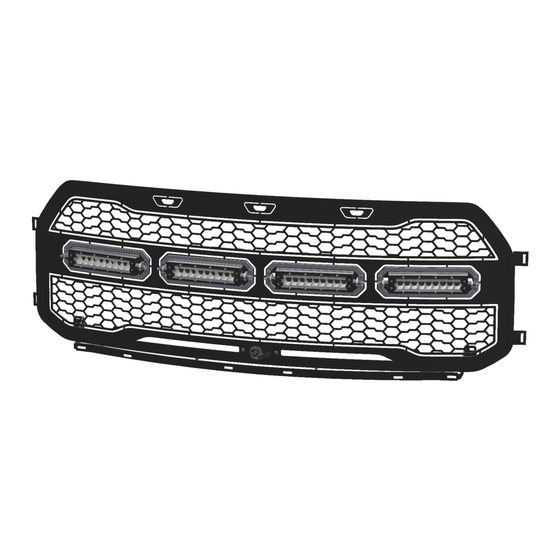
- Page 1 Instruction Manual P/N: 79-21001L Scorpion Grille Make: Ford Model: F-150 Raptor Year: 17-20 Engine: V6 – 3.5L (tt)
- Page 2 • Please read the entire instruction before proceeding. • Ensure all components listed are present. • Ensure you have all necessary tools before proceeding. • Disconnect the negative battery terminal before proceeding. • If you are missing any of the components, call customer support 951 493 7100 Qty.
- Page 4 Note: Before you begin, use “Painters Tape” to apply a protective guard around the work areas (fender and bumper valance). This will help protect the paint and finish of your vehicle. 1. Disconnect the negative battery terminal. 2. Locate ten (10) plastic clips on top of radiator shroud cover and one (1) additional on each side located at the top of the headlight body panel cover.
- Page 5 4. The headlight body panel needs to be removed. You will need to gently pull the panel out of the clips on the lower grille and the headlight. After the clips are out, continue to pull carefully until the headlight body panel is out from behind the headlight.
- Page 6 5. Remove the one (1) bolt located on each side of the grille. Save for reinstallation.
- Page 7 6. Located near the hood latch, disconnect the two (2) electrical connectors. 7. Remove the four (4) bolts across the top of the grille. Save for reinstallation. 8. Remove three (3) push pins on each side of the grille. Save for reinstallation.
- Page 8 9. Remove the grille from the truck.
- Page 9 10. Remove the lower trim body panel from the factory grille by pulling gently to release the clips which retain it. Save for reinstallation.
- Page 10 11. Remove the seven (7) nuts that line the outside edge and the one (1) screw that secures the active shutter assembly. 12. Remove the four (4) plastic clips located on the top lip. 13. Remove the wiring connector for the running lights and air temperature sensor from the active shutter grille.
- Page 11 16. Remove the factory studs left after removing the nuts and discard 17. Set the active shutter assembly to the side. Save for reinstallation.
- Page 12 18. Remove the wire loom from the grille that connects the running lights and the air temperature sensor. Save for reinstallation. 19. Mark the three (3) running lights before removing them so you know the location (Left, Center, Right). Remove the three (3) running lights from the grille. Save for reinstallation. 20.
- Page 13 Note: To prevent scratching the aFe Scorpion grille while preforming assembly, use a protective covering between the grille and a flat surface. 21. Remove the supplied aFe Scorpion grille from the box and place it on a flat surface for assembly.
- Page 14 Note: Do the next step only if not installed from aFe. 22. Install the main lower grille bracket using four (4) of the supplied 10-32 flange nuts and tighten.
- Page 15 Note: Do the next step only if not installed from aFe. 23. Install six (6) of the supplied 6-32 nylon locknuts 3/8” (.375) from the grille. This will act as a stop for the light when it is installed. Make sure that the outside flat edges of the nuts are facing towards each other.
- Page 16 24. Install the factory running lights (removed in Step 19) onto the studs. Use the six (6) remaining 6-32 nylon locknuts to secure the running lights to the aFe Scorpion grille. Tighten the nuts.
- Page 17 25. Install the supplied back plate aFe logo using the two (2) supplied 10-32 x 1/2" button head screws (black) and two (2) supplied 10-32 flange nuts. Tighten the back plate aFe logo to the aFe Scorpion grille.
- Page 18 26. Route the air temperature sensor and running light wiring loom around the outside edge of the grille (on the left side). 27. Attach the factory wiring harness to the running lights. 28. Secure the wiring harness with two (2) supplied cable ties. There are holes in the grille that are used for attaching the wiring to the grille with the factory push in wiring holders.
- Page 19 29. Remove and discard the two (2) nuts from each of the supplied 6” single row LED lights.
- Page 20 Note: Depending on your preferred look of the vehicle, you have the option to install the raw aluminum trim pieces or leave them off. Note: Please read the instruction below prior to installation. 30. Begin by taping one (1) of the supplied raw aluminum trim pieces on the front of the aFe Scorpion grille using two (2) pieces of painter’s tape (one on the top and one on the bottom).
- Page 21 32. Install the four (4) supplied cable clamps and four (4) supplied 8” cable ties to support the wires from the lights. 33. Plug the two (2) supplied Y-adapters into the light wiring harness.
- Page 22 34. Secure all the wires with one (1) supplied 8” cable ties.
- Page 23 35. Start the reassembly by reattaching the temperature sensor to the active shutter assembly.
- Page 24 36. Lay the active grille assembly over the aFe Scorpion grille and center. Make sure that when you are laying the active shutter grille over the aFe Scorpion grille, the metal tabs on the aFe Scorpion grille go over the top of the active shutter grille.
- Page 25 39. Before installing the aFe Scorpion grille, install the supplied power harness. The red wire goes on the positive battery terminal (+) and the black wire goes on the negative battery terminal (-). You will need to mount the switch inside the cab or to an available prewired switch. Use seven (7) 8” cable ties to secure the wiring loom to the vehicle.
- Page 26 40. Install the lower trim body panel onto the aFe Scorpion grille by pushing the retaining clips into supplied bracket attached to the aFe Scorpion grille. You may need to support the bracket when attaching the lower trim body panel. 41.
- Page 27 43. Center the grille assembly and install the four (4) factory screws removed in Step 7. Tighten to factory specifications.
- Page 28 Factory Clips Supplied Clips Note: The left photo is what the stock headlight body panel clips look like. The right photo is what the headlight body panel will look like after the new clips are installed. 44. Remove two (2) factory headlight body panel retainer clips from each of the left and the right headlight body panels.
- Page 29 46. Reinstall the three (3) push pins removed in Step 8 on each side of the grille.
- Page 30 47. Reinstall the factory bolts that were removed in Step 5 on each side of the grille.
- Page 31 48. Reinstall both headlight body panels by carefully pushing them into place.
- Page 32 49. Use two (2) supplied 1/4-20 X 3/4" screws, two (2) supplied 1/4" washers, and two (2) supplied 1/4" nylon locknuts to secure the head light body panel on both sides (one per side). Tighten all the hardware.
- Page 33 50. Plug the two wire connections back in on the top of the grille assembly.
- Page 34 51. Reinstall the radiator shroud cover and reinstall the twelve (10) push pins to secure it into position. 52. Reconnect the negative battery terminal.
- Page 35 53. Remove all the painter’s tape if any was applied. 54. Installation is now complete.
- Page 36 This Page Was Left Intentionally Blank...
- Page 37 This Page Was Left Intentionally Blank...
- Page 38 ONLY EQUIPPED TO PROVIDE BASIC TECHNICAL ASSISTANCE DUE TO THE DIVERSITY OF VEHICLES, VEHICLE OPTIONS & MODIFICATIONS AND LIGHTING. CONFIGURATION OPTIONS AVAILABLE. aFe Power products cannot be held liable due to improper component installation and / or faulty wiring. GENERAL GUIDELINES: LED Lights &...
- Page 39 Power Scorpion Grilles with gloss black powder coated finish may be washed regularly as you would when caring for your vehicles finish using soap and water. aFe Power Scorpion Grilles should be waxed at the same time that you wax the vehicle. As a rule, anything you use to clean your vehicles painted surfaces can be used to clean and maintain your aFe Power Scorpion Grille.
- Page 40 252 Granite Street Corona, CA 92879 TEL: 951.493.7100 • TECH: 951.493.7100 x23 E-Mail: Tech@aFepower.com 06-81291 2/26/2020 DK...
Need help?
Do you have a question about the Scorpion 79-21001L and is the answer not in the manual?
Questions and answers