Table of Contents
Advertisement
Advertisement
Table of Contents

Related Manuals for Supermicro SuperO X10DRC-T4+


Summary of Contents for Supermicro SuperO X10DRC-T4+
- Page 1 X10DRC-T4+ X10DRC-LN4+ X10DRi-T4+ X10DRi-LN4+ USER’S MANUAL Revision 1.0b...
- Page 2 This product, including software and docu- mentation, is the property of Supermicro and/or its licensors, and is supplied only under a license. Any use or reproduction of this product is not allowed, except as expressly permitted by the terms of said license.
-
Page 3: About This Motherboard
Intel® Node Manager 3.0. This motherboard is ideal for visualization, CRM, storage, and general server platforms. Please refer to our website (http://www. supermicro.com) for CPU and memory support updates. Manual Organization Chapter 1 describes the features, specifications and performance of the moth- erboard. -
Page 4: Conventions Used In The Manual
X10DRC/i-LN4+/-T4+ Motherboard User’s Manual Conventions Used in the Manual Pay special attention to the following symbols for proper system installation: Warning: Important information given to ensure proper system installation or to prevent damage to the components or injury to yourself; Note: Additional information given to differentiate between models or instructions provided for proper system setup. -
Page 5: Contacting Supermicro
Super Micro Computer, Inc. 980 Rock Ave. San Jose, CA 95131 U.S.A. Tel: +1 (408) 503-8000 Fax: +1 (408) 503-8008 Email: marketing@supermicro.com (General Information) support@supermicro.com (Technical Support) Website: www.supermicro.com Europe Address: Super Micro Computer B.V. Het Sterrenbeeld 28, 5215 ML... -
Page 6: Table Of Contents
System Health Monitoring ................1-12 ACPI Features ....................1-13 Power Supply ....................1-13 Advanced Power Management ..............1-14 Intel Intelligent Power Node Manager (NM) (Available when the Supermicro ® Power Manager [SPM] is Installed) .............. 1-14 Management Engine (ME) ................1-14 Chapter 2 Installation Standardized Warning Statements .............. - Page 7 Table of Contents NMI Button ....................2-22 Power LED ....................2-22 HDD/UID LED ..................2-23 NIC1/NIC2 LED Indicators ............... 2-23 Overheat (OH)/Fan Fail/PWR Fail/UID LED ..........2-24 Power Fail LED ..................2-24 Reset Button ................... 2-25 Power Button ................... 2-25 Connecting Cables ..................
- Page 8 X10DRC/i-LN4+/-T4+ Motherboard User’s Manual 2-10 SATA/SAS Connections ................2-41 SATA 3.0 Ports ..................2-41 SAS 3.0 Ports (for the X10DRC-LN4+/T4+) ..........2-42 Chapter 3 Troubleshooting Troubleshooting Procedures ................3-1 Technical Support Procedures ................ 3-5 Battery Removal and Installation ..............3-6 Frequently Asked Questions ................
-
Page 9: Chapter 1 Overview
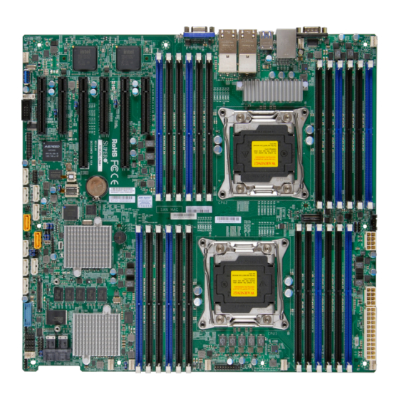
Checklist Congratulations on purchasing your computer motherboard from an acknowledged leader in the industry. Supermicro boards are designed with the utmost attention to detail to provide you with the highest standards in quality and performance. Please check that the following items have all been included with your motherboard. - Page 10 X10DRC/i-LN4+/-T4+ Motherboard User’s Manual X10DRC/i-LN4+/-T4+ Motherboard Image Note: All graphics shown in this manual were based upon the latest PCB Revision available at the time of publishing of the manual. The motherboard you've received may or may not look exactly the same as the graphics shown in this manual.
-
Page 11: Motherboard Layout
IPMI CODE CPU1 JSD1 Intel PCH JWD1 JPME2 CLOSE 1st JBT1 OPEN 1st LSI 3108 JS39 T-SGPIO1 SAS CTRL T-SGPIO2 S-SGPIO1 FANB Front CTRL Panel FAN1 Note: For the latest CPU/Memory updates, please refer to our website at http://www.supermicro.com/products/motherboard/ for details. - Page 12 X10DRC/i-LN4+/-T4+ Motherboard User’s Manual X10DRC/i-LN4+/-T4+ Quick Reference COM1 IPMI_LAN LAN1/2 LAN3/4 JUIDB1 USB4/5 LAN CTRL LAN CTRL (3.0) USB 0/1 JIPMB1 CPU2 CLOSE 1st LEDM1 BIOS JBAT1 OPEN 1st BAR CODE BIOS MAC CODE LICENSE X10DRC/i-LN4+(-T4+) SAN MAC SAS CODE Rev.
- Page 13 Chapter 1: Overview X10DRC/i-LN4+/-T4+ Jumpers Jumper Description Default Setting JBT1 Clear CMOS/Reset BIOS Configuration See Chapter 2 C1/JI SMB to PCI-E Slots Pins 1-2 (Enabled) JPB1 BMC Enable Pins 1-2 (Enabled) JPG1 VGA Enable Pins 1-2 (Enabled) JPLAN1 GLAN1/2 Enable (X10DRC/i-LN4+) Pins 1-2 (Enabled) 10G(T)_LAN1/2 Enable (X10DRC/i-T4+) JPLAN2...
- Page 14 X10DRC/i-LN4+/-T4+ Motherboard User’s Manual (CPU2) Slot1 PCI-Express 3.0 x8 Slot from CPU2 (CPU2) Slot2 PCI-Express 3.0 x8 Slot from CPU2 (CPU1) Slot3 PCI-Express 3.0 x16 Slot from CPU1 (CPU2) Slot4 PCI-Express 2.0 x4 in x8 Slot from CPU2 (CPU2) Slot5 PCI-Express 3.0 x16 Slot from CPU2 (CPU2) Slot6 PCI-Express 3.0 x8 Slot from CPU2...
-
Page 15: Motherboard Features
Registered (RDIMM) DDR4 (288-pin) ECC modules 2133/1866/1600 MHz in 24 slots Note: Memory speed support is pending on the CPUs used in the motherboard. For the latest CPU/memory updates, please refer to our website at http://www.supermicro.com/ products/motherboard. DIMM sizes • DIMM Up to 64 GB (per DIMM) @ 1.2V... -
Page 16: Peripheral Devices
Main switch override mechanism • Power-on mode for AC power recovery • Intel Intelligent Power Node Manager 3.0 (Avail- ® able when the Supermicro Power Manager (SPM) is installed and special power supply used. See Page 1-14.) • Management Engine (ME) - Page 17 Note 2: CPU Maximum Thermal Design Power (TDP) is subject to chassis and heatsink cooling restrictions. For proper thermal management, please check the chassis and heatsink specifications for proper CPU TDP sizing. Note 3: For IPMI Configuration Instructions, please refer to the Embedded IPMI Configuration User's Guide available @ http://www.supermicro.com/ support/manuals/.
-
Page 18: System Block Diagram
X10DRC/i-LN4+/-T4+ Motherboard User’s Manual Gen2 x4 (7-0) (15-8) PE2 PE3 PE1 DM1 PROCESSOR2 9.6G PROCESSOR1 PE2 PE3 PE1 DM1 (15-0) 6GB/s SATA Gen2 x4 USB 3.0 I350/ x8 (8-15) USB 3.0 X540/ SAGEVILL PCH 612 I350/ x8 (0-7) X540/ SAGEVILL USB 2.0 PCI-E USB 2.0... -
Page 19: Processor And Chipset Overview
Chapter 1: Overview Processor and Chipset Overview Built upon the functionality and capability of the Intel E5-2600v3 Series Proces- sors (Socket R3) and the Intel C612 PCH, the X10DRC/i-LN4+/-T4+ motherboard provides the best balanced solution of performance, power efficiency, and features to address the diverse needs of next-generation data server platforms. -
Page 20: Special Features
X10DRC/i-LN4+/-T4+ Motherboard User’s Manual Special Features Recovery from AC Power Loss The Basic I/O System (BIOS) provides a setting that determines how the system will respond when AC power is lost and then restored to the system. You can choose for the system to remain powered off (in which case you must press the power switch to turn it back on), or for it to automatically return to the power-on state. -
Page 21: Acpi Features
Chapter 1: Overview ACPI Features ACPI stands for Advanced Configuration and Power Interface. The ACPI specifica- tion defines a flexible and abstract hardware interface that provides a standard way to integrate power management features throughout a system, including its hardware, operating system and application software. This enables the system to automatically turn on and off peripherals such as CD-ROMs, network cards, hard disk drives and printers. -
Page 22: Advanced Power Management
Intel Intelligent Power Node Manager (NM) (Available ® when the Supermicro Power Manager [SPM] is Installed) The Intel Intelligent Power Node Manager 3.0 (IPNM) provides your system with ® real-time thermal control and power management for maximum energy efficiency. -
Page 23: Chapter 2 Installation
The following statements are industry-standard warnings, provided to warn the user of situations which have the potential for bodily injury. Should you have questions or experience difficulty, contact Supermicro's Technical Support department for assis- tance. Only certified technicians should attempt to install or configure components. - Page 24 X10DRC/i-LN4+/-T4+ Motherboard User’s Manual Attention Danger d'explosion si la pile n'est pas remplacée correctement. Ne la remplacer que par une pile de type semblable ou équivalent, recommandée par le fabricant. Jeter les piles usagées conformément aux instructions du fabricant. ¡Advertencia! Existe peligro de explosión si la batería se reemplaza de manera incorrecta.
-
Page 25: Product Disposal
Chapter 2: Installation Product Disposal Warning! Ultimate disposal of this product should be handled according to all national laws and regulations. 製品の廃棄 この製品を廃棄処分する場合、 国の関係する全ての法律 ・ 条例に従い処理する必要が あります。 警告 本产品的废弃处理应根据所有国家的法律和规章进行。 警告 本產品的廢棄處理應根據所有國家的法律和規章進行。 Warnung Die Entsorgung dieses Produkts sollte gemäß allen Bestimmungen und Gesetzen des Landes erfolgen. -
Page 26: Static-Sensitive Devices
X10DRC/i-LN4+/-T4+ Motherboard User’s Manual القىانين واللىائح الىطنية جميع وفقا ل ينبغي التعامل معه هذا المنتج من التخلص النهائي عند 경고! 이 제품은 해당 국가의 관련 법규 및 규정에 따라 폐기되어야 합니다. Waarschuwing De uiteindelijke verwijdering van dit product dient te geschieden in overeenstemming met alle nationale wetten en reglementen. -
Page 27: Motherboard Installation
Chapter 2: Installation Motherboard Installation All motherboards have standard mounting holes to fit different types of chassis. Make sure that the locations of all the mounting holes for both motherboard and chassis match. Although a chassis may have both plastic and metal mounting fas- teners, metal ones are highly recommended because they ground the motherboard to the chassis. -
Page 28: Installing The Motherboard
X10DRC/i-LN4+/-T4+ Motherboard User’s Manual Installing the Motherboard Note: Always connect the power cord last, and always remove it before adding, removing or changing any hardware components. 1. Install the I/O shield into the chassis. 2. Locate the mounting holes on the motherboard. 3. -
Page 29: Processor And Heatsink Installation
CPU socket cap is in place and none of the socket pins are bent; otherwise, contact your retailer immediately. • Refer to the Supermicro website for updates on CPU support. Installing the LGA2011 Processor 1. There are two load levers on the LGA2011 socket. To open the socket cover, first press and release the load lever labeled 'Open 1st'. - Page 30 X10DRC/i-LN4+/-T4+ Motherboard User’s Manual 2. Press the second load lever labeled 'Close 1st' to release the load plate that covers the CPU socket from its locking position. Pull the lever away Press down on the Load from the socket Lever labeled 'Close 1st' 3.
- Page 31 Chapter 2: Installation 4. Use your thumb and the index finger to loosen the lever and open the load plate. 5. Using your thumb and index finger, hold the CPU on its edges. Align the CPU keys, which are semi-circle cutouts, against the socket keys. Socket Keys CPU Keys 6.
- Page 32 X10DRC/i-LN4+/-T4+ Motherboard User’s Manual 7. With the CPU inside the socket, inspect the four corners of the CPU to make sure that the CPU is properly installed. Gently close Push down and lock the the load plate. lever labeled 'Close 1st'. 8.
-
Page 33: Installing A Passive Cpu Heatsink
Chapter 2: Installation Installing a Passive CPU Heatsink 1. Do not apply any thermal grease to the heatsink or the CPU die -- the re- quired amount has already been applied. 2. Place the heatsink on top of the CPU so that the four mounting holes are aligned with those on the Motherboard and the Heatsink Bracket underneath. -
Page 34: Removing The Heatsink
X10DRC/i-LN4+/-T4+ Motherboard User’s Manual Removing the Heatsink Warning: We do not recommend that the CPU or the heatsink be removed. However, if you do need to uninstall the heatsink, please follow the instructions below to uninstall the heatsink to avoid damaging the CPU or the CPU socket. 1. -
Page 35: Installing And Removing The Memory Modules
Chapter 2: Installation Installing and Removing the Memory Modules Note: Check Supermicro's website for recommended memory modules. CAUTION Exercise extreme care when installing or removing DIMM modules to prevent any possible damage. Installing & Removing DIMMs 1. Insert the desired number of DIMMs into the memory slots, starting with P1-DIMM A1. - Page 36 2133/1866/1600 MHz in 24 slots. Memory speed support is pending on the CPUs installed in your system. For the latest memory updates, please refer to our website a at http://www.supermicro.com/products/motherboard. Processor & Memory Module Population Configuration For memory to work properly, follow the tables below for memory installation.
- Page 37 Chapter 2: Installation Populating DDR4 RDIMM/LRDIMM Memory Modules 2-15...
-
Page 38: Control Panel Connectors And I/O Ports
X10DRC/i-LN4+/-T4+ Motherboard User’s Manual Control Panel Connectors and I/O Ports The I/O ports are color coded in conformance with the industry standards. See the picture below for the colors and locations of the various I/O ports. Back Panel Connectors and I/O Ports BAR CODE BIOS MAC CODE... -
Page 39: Serial Ports
Chapter 2: Installation Serial Ports Serial COM) Ports Pin Definitions Two COM connections (COM1 & Pin # Definition Pin # Definition COM2) are located on the mother- board. COM1 is located on the Back- plane I/O panel. COM2, located next to CPU2 PCI-E Slot1, provides front access support. -
Page 40: Universal Serial Bus (Usb)
X10DRC/i-LN4+/-T4+ Motherboard User’s Manual Universal Serial Bus (USB) Back Panel USB (2.0) 0/1, 2/3 Pin Definitions Two USB 2.0 ports (USB 0/1) and two Pin# Definition Pin# Definition USB 3.0 ports (USB 4/5), located on the I/O backpanel, provide backpanel USB_PN1 USB_PN0 USB support. -
Page 41: Glan/10G-Lan (Tlan) Ports & Ipmi_Lan Port
Chapter 2: Installation GLAN/10G-LAN (TLAN) Ports & IPMI_LAN Port Four Ethernet ports (LAN1/2, LAN3/4) are located on the I/O backplane on the motherboard. These Ethernet ports support Gigabit LANs on the X10DRC/i-LN4+ and support 10G-LANs on the X10DRC/i-T4+. In addition, an IPMI_LAN, located above USB 0/1 ports, can be used for IPMI SOL (Serial-over LAN) support. -
Page 42: Unit Identifier Switch/Uid Led Indicator
X10DRC/i-LN4+/-T4+ Motherboard User’s Manual Unit Identifier Switch/UID LED Indicator UID Switch A rear Unit Identifier (UID) switch and a rear Pin# Definition UID LED is located on the IO back panel. Ground The front UID is located on pin 13 on the Ground Front Panel Control (JF1), and the front Button In... -
Page 43: Front Control Panel
These connectors are designed specifically for use with Supermicro's server chassis. See the figure below for the descriptions of the various control panel buttons and LED indicators. Refer to the following section for descriptions and pin definitions. -
Page 44: Front Control Panel Pin Definitions
X10DRC/i-LN4+/-T4+ Motherboard User’s Manual Front Control Panel Pin Definitions NMI Button NMI Button Pin Definitions (JF1) The non-maskable interrupt button Pin# Definition header is located on pins 19 and 20 Control of JF1. Refer to the table on the right Ground for pin definitions. -
Page 45: Hdd/Uid Led
Chapter 2: Installation HDD/UID LED HDD LED Pin Definitions (JF1) The HDD LED connection is located Pin# Definition on pins 13 and 14 of JF1. Attach a UID Switch cable to pin 14 to show HDD activity HD Active status. Attach a cable to pin 13 to use UID switch. -
Page 46: Overheat (Oh)/Fan Fail/Pwr Fail/Uid Led
X10DRC/i-LN4+/-T4+ Motherboard User’s Manual Overheat (OH)/Fan Fail/PWR Fail/ OH/Fan Fail/ PWR Fail/Blue_UID UID LED LED Pin Definitions (JF1) Pin# Definition Connect an LED cable to pins 7 and Blue_UID LED 8 of the front control panel to use the Overheat/Fan Fail/Power Fail and OH/Fan Fail/Power Fail UID LED connections. -
Page 47: Reset Button
Chapter 2: Installation Reset Button Reset Button Pin Definitions (JF1) The Reset Button connection is located Pin# Definition on pins 3 and 4 of JF1. Attach it to a Reset hardware reset switch on the computer Ground case. Refer to the table on the right for pin definitions. -
Page 48: Connecting Cables
X10DRC/i-LN4+/-T4+ Motherboard User’s Manual Connecting Cables Power Connectors ATX Power 24-pin Connector Pin Definitions (JPW1) A 24-pin main power supply connector Pin# Definition Pin # Definition (J24), and two 8-pin CPU power connec- +3.3V +3.3V tors (JPWR1/JPWR2) are located on the -12V (NC) +3.3V motherboard. -
Page 49: Fan Headers
Chapter 2: Installation Fan Headers Fan Header Pin Definitions This motherboard has nine system/CPU Pin# Definition fan headers (Fan 1-Fan 6, Fan A-Fan Ground C) on the motherboard. All these 4-pin +12V fans headers are backward compatible Tachometer with the traditional 3-pin fans. However, PWR Modulation fan speed control is available for 4-pin fans only. -
Page 50: Internal Speaker
X10DRC/i-LN4+/-T4+ Motherboard User’s Manual Internal Speaker Internal Buzzer Pin Definition The Internal Speaker (SP1) can be Pin# Definitions used to provide audible indications for Pin 1 Pos. (+) Beep In various beep codes. See the table on Pin 2 Neg. (-) Alarm the right for pin definitions. -
Page 51: Tpm/Port 80 Header
Chapter 2: Installation TPM/Port 80 Header TPM/Port 80 Header Pin Definitions A Trusted Platform Module/Port 80 Pin # Definition Pin # Definition header is located at JTPM1 to provide LCLK TPM support and Port 80 connection. LFRAME# <(KEY)> Use this header to enhance system LRESET# +5V (X) performance and data security. -
Page 52: Power Smb (I C) Connector
X10DRC/i-LN4+/-T4+ Motherboard User’s Manual Power SMB (I C) Connector PWR SMB Pin Definitions Power System Management Bus (I Pin# Definition connector (JPI C1) monitors power Clock supply, fan and system temperatures. Data See the table on the right for pin PMBUS_Alert definitions. -
Page 53: T-Sgpio1/2 & S-Sgpio1 Headers
Chapter 2: Installation T-SGPIO1/2 & S-SGPIO1 Headers T-SGPIO/S-SGPIO Headers Pin Definitions Three SGPIO (Serial Link Gener- Pin# Definition Definition al Purpose Input/Output) headers are located on the motherboard. T- Ground Data SGPIO1/2 support onboard I-SATA Load Ground connections from the Intel PCH, and Clock S-SGPIO1 supports onboard S-SATA Note: NC= No Connection... -
Page 54: Jumper Settings
X10DRC/i-LN4+/-T4+ Motherboard User’s Manual Jumper Settings Explanation of Jumpers Connector Pins To modify the operation of the mother- board, jumpers can be used to choose between optional settings. Jumpers create Jumper shorts between two pins to change the function of the connector. Pin 1 is identified with a square solder pad on the printed circuit board. -
Page 55: Cmos Clear
Chapter 2: Installation CMOS Clear JBT1 is used to clear CMOS. Instead of pins, this "jumper" consists of contact pads to prevent accidental clearing of CMOS. To clear CMOS, use a metal object such as a small screwdriver to touch both pads at the same time to short the connection. Note: Please completely shut down the system, and then short JBT1 to clear CMOS. -
Page 56: Vga Enable
X10DRC/i-LN4+/-T4+ Motherboard User’s Manual VGA Enable VGA Enable Jumper Settings Jumper JPG1 allows the user to enable Jumper Setting Definition the onboard VGA connector. The default Enabled (Default) setting is on pins 1-2 to enable the con- Disabled nection. See the table on the right for jumper settings. -
Page 57: I 2 C Bus To Pci-Exp. Slots
Chapter 2: Installation C Bus to PCI-Exp. Slots C for PCI-E slots Jumper Settings Use Jumpers JI C1 and JI C2 to con- Jumper Setting Definition nect the System Management Bus (I Pins 1-2 Enabled (Default) to PCI-Express slots to improve PCI Pins 2-3 Disabled performance. -
Page 58: Manufacturer Mode Select
X10DRC/i-LN4+/-T4+ Motherboard User’s Manual Manufacturer Mode Select ME Mode Select Jumper Settings Close pins 2-3 of Jumper JPME2 to by- Jumper Setting Definition pass SPI flash security and force the sys- Normal (Default) tem to operate in the Manufacturer mode, Manufacture Mode allowing the user to flash the system firmware from a host server for system... -
Page 59: Led Indicators
Chapter 2: Installation LED Indicators LAN Port LEDs Activity LED Link LED LAN Port LEDs Four LAN ports (LAN 1/2 & LAN 3/4) are Activity LED Link LED located on the IO back panel of the moth- Rear View (when facing the erboard. -
Page 60: Onboard Power Led
X10DRC/i-LN4+/-T4+ Motherboard User’s Manual Onboard Power LED An Onboard Power LED is located at LE2 Onboard PWR LED Indicator LED States on the motherboard. When this LED is on, Color/State Definition the system is on. Be sure to turn off the System Power Off system and unplug the power cord before Green: On... -
Page 61: Sas Heartbeat Led (For The X10Drc-Ln4+/T4+ Only)
Chapter 2: Installation SAS Heartbeat LED (for the X10DRC- SAS Heartbeat LED LED Settings LN4+/T4+ only) Color/State Definition A SAS Heartbeat LED is located at DS13 Green: Blinking SAS: Normal on the motherboard. When DS13 is blink- SAS: Disabled or ing, SAS is working properly. -
Page 62: Sas Error Led (For The X10Drc-Ln4+/T4+ Only)
X10DRC/i-LN4+/-T4+ Motherboard User’s Manual SAS Error LED (for the X10DRC- SAS Error LED LED Settings LN4+/T4+ only) Color/State Definition A SAS Error LED is located at LEDS6 on Red: On A SAS Error has occurred. the motherboard. When LEDS6 is on, a SAS error has occurred. -
Page 63: 2-10 Sata/Sas Connections
SATA_RXN the table on the right for pin definitions. SATA_RXP Ground Note: For more information on SATA HostRAID configuration, please refer to the Intel SATA HostRAID User's Guide posted on our website @ http:// www.supermicro.com.. COM1 IPMI_LAN LAN3/4 LAN1/2 JUIDB1 A. -
Page 64: Sas 3.0 Ports (For The X10Drc-Ln4+/T4+)
X10DRC/i-LN4+/-T4+ Motherboard User’s Manual SAS 3.0 Ports (for the X10DRC-LN4+/T4+) Eight SAS 3.0 ports are located at JS39 on the motherboard. These SAS ports are supported by the LSI 3108 SAS controller. These SAS ports provide serial-link signal connections, which are faster than the connections of Serial ATA (SATA). See the table on the right for pin definitions. -
Page 65: Chapter 3 Troubleshooting
Chapter 3: Troubleshooting Chapter 3 Troubleshooting Troubleshooting Procedures Use the following procedures to troubleshoot your system. If you have followed all of the procedures below and still need assistance, refer to the ‘Technical Support Procedures’ and/or ‘Returning Merchandise for Service’ section(s) in this chapter. Note: Always disconnect the power cord before adding, changing or installing any hardware components. -
Page 66: System Boot Failure
X10DRC/i-LN4+/-T4+ Motherboard User’s Manual No Video 1. If the power is on, but you have no video, remove all the add-on cards and cables. 2. Use the speaker to determine if any beep codes exist. Refer to Appendix A for details on beep codes. System Boot Failure If the system does not display POST or does not respond after the power is turned on, check the following:... -
Page 67: Memory Errors
2. Memory support: Make sure that the memory modules are supported by test- ing the modules using memtest86 or a similar utility. Note: Refer to the product page on our website http:\\www.supermicro. com for memory and CPU support and updates. - Page 68 X10DRC/i-LN4+/-T4+ Motherboard User’s Manual tings in the IPMI to make sure that the CPU and System temperatures are within the normal range. Also check the front panel Overheat LED, and make sure that the Overheat LED is not on. 5. Adequate power supply: Make sure that the power supply provides adequate power to the system.
-
Page 69: Technical Support Procedures
Technical Support Procedures Before contacting Technical Support, please take the following steps. Also, please note that as a motherboard manufacturer, Supermicro also sells motherboards through its channels, so it is best to first check with your distributor or reseller for troubleshooting services. -
Page 70: Battery Removal And Installation
X10DRC/i-LN4+/-T4+ Motherboard User’s Manual Battery Removal and Installation Battery Removal To remove the onboard battery, follow the steps below: 1. Power off your system and unplug your power cable. 2. Locate the onboard battery as shown below. 3. Using a tool such as a pen or a small screwdriver, push the battery lock out- wards to unlock it. -
Page 71: Frequently Asked Questions
Note: The SPI BIOS chip used on this motherboard cannot be removed. Send your motherboard back to our RMA Department at Supermicro for repair. For BIOS Recovery instructions, please refer to the AMI BIOS Recovery Instructions posted at http://www.supermicro.com. -
Page 72: Returning Merchandise For Service
Shipping and handling charges will be applied for all orders that must be mailed when service is complete. For faster service, You can also request a RMA authorization online (http://www.supermicro.com/RmaForm/). This warranty only covers normal consumer use and does not cover damages in- curred in shipping or from failure due to the alternation, misuse, abuse or improper maintenance of products. -
Page 73: Chapter 4 Bios
When an option is selected in the left frame, it is highlighted in white. Often a text message will accompany it. Note: the AMI BIOS has default text messages built in. Supermicro retains the option to include, omit, or change any of these text messages. -
Page 74: How To Start The Setup Utility
Flashing the wrong BIOS can cause irreparable damage to the system. In no event shall Supermicro be liable for direct, indirect, special, incidental, or consequential damages arising from a BIOS update. If you have to update the BIOS, do not shut down or reset the system while the BIOS is updating to avoid possible boot failure. - Page 75 Day MM/DD/YYYY format. The time is entered in HH:MM:SS format. Note: The time is in the 24-hour format. For example, 5:30 P.M. appears as 17:30:00. Supermicro X10DRC-T4+ Series BIOS Version: This item displays the version of the BIOS ROM used in the system.
-
Page 76: Advanced Setup Configurations
X10DRC/i-LN4+/-T4+ Motherboard User’s Manual Advanced Setup Configurations Use the arrow keys to select Advanced setup and press <Enter> to access the submenu items: Warning: Take Caution when changing the Advanced settings. An incorrect value, a very high DRAM frequency or an incorrect BIOS timing setting may cause the system to malfunction. -
Page 77: Power Configuration
Chapter 4: AMI BIOS Wait For 'F1' If Error Select Enabled to force the system to wait until the <F1> key is pressed if an error occurs. The options are Disabled and Enabled. INT19 (Interrupt 19) Trap Response Interrupt 19 is the software interrupt that handles the boot disk function. When this item is set to Immediate, the ROM BIOS of the host adaptors will "capture"... -
Page 78: Cpu Configuration
X10DRC/i-LN4+/-T4+ Motherboard User’s Manual CPU Configuration This submenu displays the following CPU information as detected by the BIOS. It also allows the user to configure CPU settings. • Processor Socket • Processor ID • Processor Frequency • Processor Max Ratio •... - Page 79 Chapter 4: AMI BIOS illegal codes to overwhelm the processor to damage the system during an attack. The options are Enable and Disable. (Refer to Intel's and Microsoft's websites for more information.) PPIN Control Select Unlock/Enable to use the Protected-Processor Inventory Number (PPIN) control in the system.
-
Page 80: Advanced Power Management Configuration
X10DRC/i-LN4+/-T4+ Motherboard User’s Manual AES-NI Select Enable to use the Intel Advanced Encryption Standard (AES) New Instruc- tions (NI) to ensure data security. The options are Enable and Disable. Intel Virtualization Technology Select Enable to use Intel Virtualization Technology support for Direct I/O VT-d sup- port by reporting the I/O device assignments to the VMM (Virtual Machine Monitor) through the DMAR ACPI tables. - Page 81 Chapter 4: AMI BIOS CPU C State Control (Available when Power Technology is set to Custom) Package C State limit Use this item to set the limit on the C-State package register. The options are C0/1 state, C2 state, C6 (non-Retention) state, and C6 (Retention) state. CPU C3 Report Select Enable to allow the BIOS to report the CPU C3 State (ACPI C2) to the operating system.
-
Page 82: Chipset Configuration
X10DRC/i-LN4+/-T4+ Motherboard User’s Manual Chipset Configuration Warning! Please set the correct settings for the items below. A wrong configuration setting may cause the system to become malfunction. North Bridge This feature allows the user to configure the settings for the Intel North Bridge. IIO Configuration EV DFX (Device Function On-Hide) Features When this feature is set to Enable, the EV_DFX Lock Bits that are located on a... - Page 83 Chapter 4: AMI BIOS II01 PORT 3A Link Speed This item configures the link speed of a PCI-E port specified by the user. The options are Gen 1 (Generation 1) (2.5 GT/s), Gen 2 (Generation 2) (5 GT/s), and Gen 3 (Generation 3) (8 GT/s). II01 PORT 3C Link Speed This item configures the link speed of a PCI-E port specified by the user.
- Page 84 X10DRC/i-LN4+/-T4+ Motherboard User’s Manual IOAT (Intel® IO Acceleration) Configuration Enable IOAT Select Enable to enable Intel I/OAT (I/O Acceleration Technology) support, which significantly reduces CPU overhead by leveraging CPU architectural improve- ments and freeing the system resource for other tasks. The options are Enable and Disable.
-
Page 85: Memory Configuration
Chapter 4: AMI BIOS • Current QPI Link Frequency • QPI Global MMIO Low Base/Limit • QPI Global MMIO High Base/Limit • QPI PCIe Configuration Base/Size Link Frequency Select Use this item to select the desired frequency for QPI Link connections. The op- tions are 6.4GB/s, 8.0GB/s, 9.6GB/s, Auto, and Auto Limited. -
Page 86: Dimm Information
X10DRC/i-LN4+/-T4+ Motherboard User’s Manual Data Scrambling Select Enabled to enable data scrambling to enhance system performance and data integrity. The options are Auto, Disabled and Enabled. DRAM RAPL (Running Average Power Limit) Baseline Use this feature to set the run-time power-limit baseline for DRAM modules. The options are Disable, DRAM RAPL Mode 0, and DRAM RAPL Mode 1. -
Page 87: South Bridge Configuration
Chapter 4: AMI BIOS Patrol Scrub Patrol Scrubbing is a process that allows the CPU to correct correctable memory errors detected on a memory module and send the correction to the requestor (the original source). When this item is set to Enable, the IO hub will read and write back one cache line every 16K cycles, if there is no delay caused by internal processing. - Page 88 X10DRC/i-LN4+/-T4+ Motherboard User’s Manual XHCI Hand-Off This is a work-around solution for operating systems that do not support XHCI (Ex- tensible Host Controller Interface) hand-off. The XHCI ownership change should be claimed by the XHCI driver. The settings are Enabled and Disabled. EHCI Hand-Off This item is for operating systems that do not support Enhanced Host Controller Interface (EHCI) hand-off.
-
Page 89: Sata Configuration
Chapter 4: AMI BIOS SATA Configuration When this submenu is selected, AMI BIOS automatically detects the presence of the SATA devices that are supported by the Intel PCH chip and displays the fol- lowing items: SATA Controller Select Enabled to enable the onboard SATA controller supported by the Intel PCH chip. - Page 90 X10DRC/i-LN4+/-T4+ Motherboard User’s Manual *If the item above "Configure SATA as" is set to IDE, the following items will display: Serial ATA Port 0~ Port 5 This item indicates that a SATA port specified by the user is installed (present) or not.
-
Page 91: Ssata Configuration
Chapter 4: AMI BIOS Port 0 ~ Port 5 Spin Up Device On an edge detect from 0 to 1, set this item to allow the PCH to start a COMRE- SET initialization to the device. The options are Enabled and Disabled. Port 0 ~ Port 5 SATA Device Type Use this item to specify if the SATA port specified by the user should be con- nected to a Solid State drive or a Hard Disk Drive. - Page 92 X10DRC/i-LN4+/-T4+ Motherboard User’s Manual sSATA Port 0 ~ Port 3 Spin Up Device On an edge detect from 0 to 1, set this item to allow the PCH to start a COMRE- SET initialization to the device. The options are Enabled and Disabled. Port 0 ~ Port 3 sSATA Device Type Use this item to specify if the sSATA port specified by the user should be con- nected to a Solid State drive or a Hard Disk Drive.
- Page 93 Chapter 4: AMI BIOS sSATA Port 0~ Port 3 This item displays the information detected on the installed sSATA drives on the particular sSATA port. • Model number of drive and capacity sSATA Port 0~ Port 3 Select Enabled to enable an sSATA port specified by the user. The options are Disabled and Enabled.
- Page 94 X10DRC/i-LN4+/-T4+ Motherboard User’s Manual PCIe/PCI/PnP Configuration The following PCI information will be displayed: • PCI Bus Driver Version • PCI Device Common Settings PCI Latency Timer Use this item to configure the PCI latency timer for a device installed on a PCI bus. Select 32 to set the PCI latency timer to 32 PCI clock cycles.
- Page 95 Chapter 4: AMI BIOS ASPM Support Use this item to set the Active State Power Management (ASPM) level for a PCI-E device. Select Auto for the system BIOS to automatically set the ASPM level based on the system configuration. Select Disabled to disable ASPM support. The options are Disabled and Auto.
-
Page 96: Super Io Configuration
X10DRC/i-LN4+/-T4+ Motherboard User’s Manual Super IO Configuration Super IO Chip AST2400 Serial Port 1 Configuration/Serial Port 2 Configuration Serial Port 1/Serial Port 2 Select Enabled to enable the onboard serial port specified by the user. The options are Enabled and Disabled. Device Settings This item displays the base I/O port address and the Interrupt Request address of a serial port specified by the user. -
Page 97: Com1 Console Redirection Settings
Chapter 4: AMI BIOS *If the item above set to Enabled, the following items will become available for configuration: COM1 Console Redirection Settings Terminal Type Use this item to select the target terminal emulation type for Console Redirec- tion. Select VT100 to use the ASCII Character set. Select VT100+ to add color and function key support. - Page 98 X10DRC/i-LN4+/-T4+ Motherboard User’s Manual VT-UTF8 Combo Key Support Select Enabled to enable VT-UTF8 Combination Key support for ANSI/VT100 terminals. The options are Enabled and Disabled. Recorder Mode Select Enabled to capture the data displayed on a terminal and send it as text messages to a remote server.
- Page 99 Chapter 4: AMI BIOS SOL/COM2 Console Redirection Settings Use this feature to specify how the host computer will exchange data with the client computer, which is the remote computer used by the user. Terminal Type Use this feature to select the target terminal emulation type for Console Redirec- tion.
- Page 100 X10DRC/i-LN4+/-T4+ Motherboard User’s Manual VT-UTF8 Combo Key Support Select Enabled to enable VT-UTF8 Combination Key support for ANSI/VT100 terminals. The options are Enabled and Disabled. Recorder Mode Select Enabled to capture the data displayed on a terminal and send it as text messages to a remote server.
- Page 101 Chapter 4: AMI BIOS Serial Port for Out-of-Band Management/Windows Emergency Management Services (EMS) The submenu allows the user to configure Console Redirection settings to support Out-of-Band Serial Port management. EMS Console Redirection Select Enabled to use a COM port selected by the user for EMS Console Redirec- tion.
- Page 102 X10DRC/i-LN4+/-T4+ Motherboard User’s Manual Flow Control Use this item to set the flow control for Console Redirection to prevent data loss caused by buffer overflow. Send a "Stop" signal to stop data-sending when the receiving buffer is full. Send a "Start" signal to start data-sending when the receiving buffer is empty.
-
Page 103: Acpi Settings
EV DFX (Device Function On-Hide) support for the system to work properly. (EV DFX is under "IIO Configuration" in the "Chipset/North Bridge" submenu on Page 4-10). Note 2: For more information on TPM, please refer to the TPM manual at http://www.supermicro.com/manuals/other/AOM-TPM-9655V_9655H.pdf ACPI Settings WHEA Support... -
Page 104: Event Logs
X10DRC/i-LN4+/-T4+ Motherboard User’s Manual Event Logs Use this feature to configure Event Log settings. Change SMBIOS Event Log Settings This feature allows the user to configure SMBIOS Event settings. Enabling/Disabling Options SMBIOS Event Log Select Enabled to enable SMBIOS (System Management BIOS) Event Logging during system boot. -
Page 105: View Smbios Event Log
Chapter 4: AMI BIOS When Log is Full Select Erase Immediately to immediately erase all errors in the SMBIOS event log when the event log is full. Select Do Nothing for the system to do nothing when the SMBIOS event log is full. The options are Do Nothing and Erase Immediately. SMBIOS Event Log Standard Settings Log System Boot Event Select Enabled to log system boot events. -
Page 106: Ipmi
X10DRC/i-LN4+/-T4+ Motherboard User’s Manual IPMI Use this feature to configure Intelligent Platform Management Interface (IPMI) settings. BMC (Baseboard Management Controller) Firmware Revision This item indicates the BMC firmware revision used in your system. IPMI Status This item indicates the status of the IPMI firmware installed in your system. System Event Log ... -
Page 107: Bmc Network Configuration
Chapter 4: AMI BIOS When SEL is Full This feature allows the user to determine what the AMI BIOS should do when the system event log is full. Select Erase Immediately to erase all events in the log when the system event log is full. The options are Do Nothing and Erase Immediately. Note: After making changes on a setting, be sure to reboot the system for the changes to take effect. -
Page 108: Security Settings
X10DRC/i-LN4+/-T4+ Motherboard User’s Manual Security Settings This menu allows the user to configure the following security settings for the system. Password Check Select Setup for the system to prompt for a password upon entering the BIOS setup utility. Select Always for the system to prompt for a password at bootup and upon entering the BIOS Setup utility. -
Page 109: Boot Settings
Chapter 4: AMI BIOS Boot Settings Use this feature to configure Boot Settings: Boot Configuration Setup Prompt Timeout Use this item to indicate how many seconds the system shall wait for the BIOS setup activation key to respond before the system starts to boot. The default setting is 1. Boot Mode Select Use this item to select the type of device to be used for system boot. - Page 110 X10DRC/i-LN4+/-T4+ Motherboard User’s Manual Delete Boot Option Use this item to select a boot device to delete from the boot priority list. Delete Boot Option Select the target boot device to delete. Hard Disk Drive BBS Priorities • Legacy Boot Order #1 ...
-
Page 111: Save & Exit
Chapter 4: AMI BIOS Save & Exit Select the Save & Exit tab from the BIOS setup screen to configure the settings below. Discard Changes and Exit Select this option to exit from the BIOS setup without making any permanent changes to the system configuration, and reboot the computer. - Page 112 X10DRC/i-LN4+/-T4+ Motherboard User’s Manual Save As User Defaults Select this item and press <Enter> to save the current BIOS settings as user's default settings for future use. Restore User Defaults Select this item and press <Enter> to retrieve user-defined settings that were previ- ously saved for future use.
-
Page 113: Appendix A Bios Error Beep Codes
Appendix A: BIOS POST Error Codes Appendix A BIOS Error Beep Codes During the POST (Power-On Self-Test) routines, which are performed at each system boot, errors may occur. Non-fatal errors are those which, in most cases, allow the system to continue to boot. - Page 114 X10DRC/i-LN4+/-T4+ Motherboard User’s Manual Notes...
-
Page 115: Appendix B Software Installation Instructions
Appendix B Software Installation Instructions B-1 Installing Software Programs The Supermicro ftp site contains drivers and utilities for your system at ftp://ftp. supermicro.com. Some of these must be installed, such as the chipset driver. After accessing the ftp site, go into the CDR_Images directory and locate the ISO file for your motherboard. -
Page 116: B-2 Installing Superdoctor5
X10DRC/i-LN4+/-T4+ Motherboard User’s Manual B-2 Installing SuperDoctor5 The Supermicro SuperDoctor® 5 is a hardware monitoring program that functions in a command-line or web-based interface in Windows and Linux operating systems. The program monitors system health information such as CPU temperature, system voltages, system power consumption, fan speed, and provides alerts via email or Simple Network Management Protocol (SNMP). -
Page 117: Appendix C Uefi Bios Recovery Instructions
Flashing the wrong BIOS can cause irreparable damage to the system. In no event shall Supermicro be liable for direct, indirect, special, incidental, or consequential damages arising from a BIOS update. If you need to update the BIOS, do not shut down or reset the system while the BIOS is updating to avoid possible boot failure. - Page 118 Root "\" Directory of a USB device or a writeable CD/DVD. Note: If you cannot locate the "Super.ROM" file in your driver disk, visit our website at www.supermicro.com to download the BIOS image into a USB flash device and rename it "Super.ROM" for BIOS recovery use.
- Page 119 Appendix C: UEFI BIOS Recovery 4. After locating the new BIOS binary image, the system will enter the BIOS Recovery menu as shown below. Note: At this point, you may decide if you want to start with BIOS recovery. If you decide to proceed with BIOS recovery, follow the procedures below. 5.
- Page 120 X10DRC/i-LN4+/-T4+ Motherboard User’s Manual 6. After the process of BIOS recovery is completed, press any key to reboot the system. 7. Using a different system, extract the BIOS package into a bootable USB flash drive. 8. When a DOS prompt appears, enter FLASH.BAT BIOSname.### at the prompt.
- Page 121 (Disclaimer Continued) The products sold by Supermicro are not intended for and will not be used in life support systems, medical equipment, nuclear facilities or systems, aircraft, aircraft devices, aircraft/emergency communication devices or other critical systems whose failure to perform be reasonably expected to result in significant injury or loss of life or catastrophic property damage.
Need help?
Do you have a question about the SuperO X10DRC-T4+ and is the answer not in the manual?
Questions and answers