Table of Contents
Advertisement
Quick Links
Advertisement
Table of Contents
Troubleshooting

Related Manuals for Teledyne PIXIS


Summary of Contents for Teledyne PIXIS
- Page 1 PIXIS System Manual 4411-0106 Issue 5 May 22, 2019 www.princetoninstruments.com...
- Page 2 Trenton, NJ 08619 TEL: 800-874-9789 / 609-587-9797 FAX: 609-587-1970 All rights reserved. No part of this publication may be reproduced by any means without the written permission of Teledyne Princeton Instruments. Printed in the United States of America. IntelliCal, LightField, and PVCAM are registered trademarks of Teledyne Digital Imaging US, Inc.
-
Page 3: Table Of Contents
PIXIS Camera and System Maintenance........26... - Page 4 Mount the PIXIS on a Spectrograph........
- Page 5 Installation Procedure ........129 C-Mount to Teledyne Acton Research Series Spectrograph Adapter ..130 D.3.1...
- Page 6 PIXIS System Manual Issue 5 Appendix E: Troubleshooting ......... . . 135 Acquisition Started but Viewer Contents Do Not Update .
- Page 7 PIXIS Rear Connector Panel........19...
- Page 8 Figure C-1: Lock Screw Location on a PIXIS ....... .123 Figure C-2: F-Mount Adapter Adjustment Ring Set Screw Locations .
- Page 9 PIXIS Rear Panel Connector Information ......19 Table 2-2: Standard PIXIS Camera System Cables......22 Table 3-1: USB Driver Files and Locations.
- Page 10 PIXIS System Manual Issue 5 This page is intentionally blank.
-
Page 11: Chapter 1: About This Manual
PIXIS Camera System Data Sheet Teledyne Princeton Instruments maintains updated documentation and user manuals on their FTP site. Visit the Teledyne Princeton Instruments FTP Site to verify that the most recent user manual is available and being referenced: ftp://ftp.piacton.com/Public/Manuals/Princeton Instruments... -
Page 12: Document Organization
• Chapter 2, System Component Descriptions This chapter provides information about the components included with a standard PIXIS camera system, as well as options that are available for purchase from Teledyne Princeton Instruments. • Chapter 3, Install Data Acquisition Software This chapter provides information about the installation of Teledyne Princeton Instruments’... -
Page 13: Conventions Used In This Document
• Appendix E, Troubleshooting This appendix provides recommended troubleshooting information for issues which may be encountered while working with a PIXIS camera system. • Appendix F, WinSpec/32/LightField Cross Reference This appendix provides cross reference information for terminology used within the WinSpec/32 and LightField application software packages. -
Page 14: Pixis Safety Information
4. Do not block air vents on the camera. Preventing the free flow of air overheats the camera and may damage it. 5. If the PIXIS camera system is used in a manner not specified by Teledyne Princeton Instruments, the... -
Page 15: Uv Coatings
Chapter 1 About this Manual 1.6.1 UV Coatings CAUTION! If using a camera with a UV (Lumogen or Unichrome™) coated CCD, protect it from unnecessary exposure to UV radiation. This radiation slowly bleaches the coating, reducing sensitivity. - Page 16 PIXIS System Manual Issue 5 This page is intentionally blank.
-
Page 17: Chapter 2: System Component Descriptions
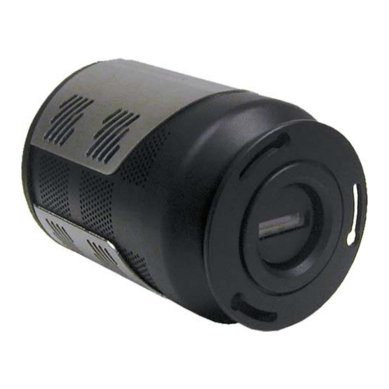
Figure 2-1: Typical System Components A typical air-cooled PIXIS system consists of the camera with a Certificate of Performance, a power supply, a USB 2.0 interface cable for your computer system, MCX to BNC adapter cables, and the user manual. -
Page 18: Pixis Camera
Issue 5 PIXIS Camera PIXIS is a fully integrated camera system. The camera contains all of the electronics necessary to read out and control the CCD device. For instance, it houses precision analog-to-digital converters (ADCs) positioned close to the CCD for lowest noise and has USB 2.0 electronics to interface with the host computer. -
Page 19: Ccd Array
2.1.2 CCD Array The PIXIS camera system offers both front- and back-illuminated CCDs in a variety of array sizes that allow you to precisely match the sensor to your application. Only scientific-grade devices are used in order to ensure the highest image fidelity, resolution, and acquisition flexibility required for scientific imaging. -
Page 20: Power
USB port located on the rear of the camera. As of this printing, you can hot plug the PIXIS camera whenever the WinX application is not running (i.e., connect or disconnect from the camera or the host computer while the camera is powered ON). -
Page 21: Cooling
System Component Descriptions 2.1.5 Cooling Dark current is reduced in PIXIS camera systems through thermoelectric cooling of the CCD arrays. Cooling by this method uses a four-stage Peltier cooler in combination with circulating air or coolant. To prevent condensation and contamination from occurring, cameras cooled this way are evacuated. -
Page 22: Cables
OUT connectors on the rear of the PIXIS 4411-0106_0006 Certificate of Performance Each PIXIS camera is shipped with a Certificate of Performance which states that the camera system has been assembled and tested according to approved Teledyne Princeton Instruments procedures. It documents the camera’s performance data as... -
Page 23: Application Software
Using the optional built-in macro record function, you can also create and edit your own macros to automate a variety of operations. WinView and WinSpec take full advantage of the versatility of the PIXIS camera and even enhance it by making integration of the detection system into larger experiments or instruments an easy, straightforward endeavor. -
Page 24: Accessories
Accessories Teledyne Princeton Instruments offers a number of optional accessories that are compatible with PIXIS. This section provides information about each of them. For complete ordering information, contact Teledyne Princeton Instruments. Internal Shutter Optional 25 or 45 mm internal shutter (dependent on CCD array size). -
Page 25: Unpack The System
If damage is not apparent but the camera cannot be operated, internal damage may have occurred in shipment. Retain all original packing materials so that the PIXIS system can be easily and safely packaged and shipped to another location or returned for service if necessary. If assistance is required at any time, contact Teledyne Princeton Instruments Customer Support. -
Page 26: Pixis Camera And System Maintenance
2.8.1 Camera Although there is no periodic maintenance that needs to be performed on a PIXIS camera, users are advised to wipe it down with a clean damp cloth from time to time. This operation should only be done on the external surfaces and with all covers secured. -
Page 27: Chapter 3: Install Data Acquisition Software
Insert the LightField Installation CD into the CD drive on the host computer and follow the on-screen prompts. 2. After the installation has been completed, reboot the host computer. 3. Connect the PIXIS system components to your computer and apply power. 4. Launch LightField, activate it, and begin experiment configuration. -
Page 28: Winx
PIXIS System Manual Issue 5 WinX This section provides information about installing WinView/32 and WinSpec 32 data acquisition software. NOTES: Before proceeding, please check to see if your computer supports USB 2.0. If it does not, install a USB 2.0 interface card. Follow the manufacturer’s instructions. -
Page 29: Table 3-1: Usb Driver Files And Locations
4. Verify the camera is connected to the host computer and that the camera power supply is turned on. 5. Reboot the host computer. Windows will detect the Teledyne Princeton Instruments USB2 Interface hardware in the PIXIS. 6. If prompted, enter the directory path(s) for the following files by either manually typing them in or browsing to their locations: •... - Page 30 PIXIS System Manual Issue 5 This page is intentionally blank.
-
Page 31: Chapter 4: System Block Diagrams
This chapter provides block diagrams of typical system configurations. Figure 4-1: Block Diagram: Typical Air-Cooled Imaging Experiment Power Supply 100/240 USB Cable Camera EXPERIMENT Figure 4-2: Block Diagram: Typical Air-Cooled Spectroscopy Experiment Power Supply 100/240 USB Cable PIXIS Camera Camera SAMPLE Spectrometer... -
Page 32: Figure 4-3: Block Diagram: Typical Liquid-Cooled Imaging Experiment
PIXIS System Manual Issue 5 Figure 4-3: Block Diagram: Typical Liquid-Cooled Imaging Experiment Figure 4-4: Block Diagram: Typical Liquid-Cooled Spectroscopy Experiment... -
Page 33: Chapter 5: Hardware Installation
Verify the power to both the PIXIS and the circulator is turned off. 2. Verify the circulator is placed a minimum of 6 inches [15.0 cm] below the PIXIS. This vertical distance should not exceed 10 feet [3 m.]... - Page 34 PIXIS System Manual Issue 5 3. Connect the PIXIS to the circulator using the respective coolant ports on both pieces of equipment. NOTES: It does not matter which hose from the circulator is connected to which coolant port on the PIXIS.
-
Page 35: Install A Lens On A C-Mount Adapter
NOTE: PIXIS cameras for imaging applications may incorporate an integral C-mount or adjustable C-mount adapter. Other mounts may be available. Contact Teledyne Princeton Instruments Customer Service for assistance. Refer to Contact Information on page 154 for complete information. -
Page 36: Install Adjustable C- To Spectroscopy-Mount Kinetics Adapter
PIXIS’ kinetics rows with the middle of the focal plane for the best spectral quality. The adapter is mounted to the front of a PIXIS camera and secured by a threaded insert screwed into the camera’s C-mount opening. - Page 37 Section 6.2.2.1, Focus and Rotational Alignment, on page 62. 7. Once the PIXIS has been focused and rotationally aligned, secure the sliding tube in place using the spectrograph set screws. 8. If already installed, use the 0.050” Hex Wrench to loosen the adapter’s two recessed locking set screws.
-
Page 38: Mount The Pixis On A Spectrograph
PIXIS System Manual Issue 5 Mount the PIXIS on a Spectrograph The PIXIS must be properly mounted to the spectrograph in order to achieve proper focus. Additional precautions must also be taken to prevent overexposure of the camera. The distance to the focal plane from the front of the mechanical assembly depends on the specific camera’s configuration. -
Page 39: External Shutter
5.6.1 External Shutter A Teledyne Princeton Instruments-supplied external shutter may be used with a PIXIS camera that does not have an internal shutter. In most situations, the external shutter is mounted on the entrance slit of a spectrograph. The shutter mount used with all Teledyne Acton Research Series spectrographs requires no disassembly. -
Page 40: Overexposure Protection
PIXIS System Manual Issue 5 5.6.1.1 Overexposure Protection Cameras that are exposed to room light or other continuous light sources will quickly become saturated. This most often occurs when operating without a shutter. If the camera is mounted to a spectrograph, close the entrance slit of the spectrograph to reduce the incident light. -
Page 41: First Light
Chapter 6: First Light Once the PIXIS camera has been configured as described in Chapter 5, Hardware Installation, acquiring data using image acquisition software is straightforward. For most applications simply: • Establish optimum performance (e.g., in WinX use Focus mode);... - Page 42 PIXIS System Manual Issue 5 Whether or not the data are displayed and/or stored depends on the data collection operation that has been selected in the application software. In WinX and LightField, the data collection operations use the Experiment Setup parameters to establish the exposure time (i.e., the period during which the signal of...
-
Page 43: Winx First Light Procedure
In order to ensure communication between the PIXIS and the host computer, the PIXIS must be powered on before launching the WinX application. If WinX is launched and the PIXIS has not already been powered on, many functions will be disabled and you will only be able to retrieve and examine previously acquired and stored data. - Page 44 PIXIS System Manual Issue 5 3. Turn on the host computer and allow it to boot up. 4. Once the host computer has finished booting up, launch WinView/32. 5. Configure the following parameters as indicated: ► • Environment dialog (Setup Environment) Check the DMA Buffer size.
- Page 45 Chapter 6 First Light ► • Experiment Setup Timing tab (Acquisition Experiment Setup…) — Timing Mode Free Run — Shutter Control Normal — Safe Mode vs. Fast Mode Fast 6. If using WinView/32 and the host computer monitor to focus the system, select Focus from the Acquisition menu.
-
Page 46: Spectroscopy Applications
6.1.2 Spectroscopy Applications The following procedure assumes that: • The PIXIS is to be operated with, and has been properly installed on, a spectrograph (e.g., Teledyne Acton Research Series 2300 spectrograph,) and is being operated in spectroscopy mode. Refer to... - Page 47 This information is read from the camera. — Shutter type Remote (entrance slit shutter). Select None if the PIXIS has no shutter and is not controlling an entrance slit shutter. — Readout mode Available modes are read from the camera.
- Page 48 — Click Install/Remove Spectrograph; — Highlight the desired spectrograph in the Supported Spectrographs list For example: • Teledyne Acton Research SP-300i for a Teledyne Acton Research SP2300i; • Teledyne Acton Research SCT320 for an IsoPlane. — Click Install Selected Spectrograph.
- Page 49 Verifying an internally mounted shutter requires access to the inside of the spectrograph. Refer to the spectrograph manual for instructions. h. Determine if the PIXIS has a shutter. Loosen and remove the camera from the spectrograph. If the CCD is visible when looking into the front of the camera, the camera does not have an internal shutter.
-
Page 50: Focus And Rotational Alignment
If this is the case, use a wavelength setting of 0.0 nm for alignment purposes. 2. With the spectrograph properly connected to the PIXIS, turn the power on and allow the spectrograph to initialize. - Page 51 Note that the way focusing is accomplished depends on the spectrograph, as follows: • Long focal-length spectrographs (e.g., Teledyne Acton Research SP-2300) The mounting adapter includes a tube that slides inside another tube to move the camera in or out as required to achieve optimum focus.
- Page 52 2. With the IsoPlane properly connected to the host computer, turn the power on, wait for the IsoPlane to initialize. 3. With the PIXIS mounted to the IsoPlane and connected to the host computer, turn on the power and wait for the PIXIS to initialize.
- Page 53 21. While watching a live display of the spectrum, select a peak to monitor. 22. Rotate the PIXIS (up to 4 degrees of rotation is possible). The peak will go from broad to narrow and back to broad. Leave the PIXIS’ rotation set for the narrowest achievable peak.
-
Page 54: Lightfield First Light Procedure
Perform the following procedure to set up and configure the system to acquire image data: Mount the test target in front of the PIXIS. 2. Turn on the camera. 3. Turn on the host computer. 4. Launch LightField. An icon representing the PIXIS should be visible within the Available Devices area. Figure 6-2. -
Page 55: Figure 6-2: Typical Lightfield Available Devices Area
Chapter 6 First Light Figure 6-2: Typical LightField Available Devices Area 5. Drag the PIXIS into the Experiment Devices area. See Figure 6-3. Figure 6-3: Typical LightField Experiment Devices Area The Experiment Settings stack on the left now displays several expanders with default parameter values configured. -
Page 56: Figure 6-4: Typical Lightfield Data Viewer
6. Click the View tab above Experiment Devices area to switch to the Data Viewer. See Figure 6-4. Figure 6-4: Typical LightField Data Viewer 7. Allow the PIXIS to locks at its default temperature. 8. Click to start Preview mode. In this mode, images are continuously acquired and displayed. See Figure 6-5. -
Page 57: Spectroscopy Applications
Refer to the spectrograph manual for additional information. • The PIXIS is being operated with a spectrograph (e.g., a Teledyne Acton Research Series 2300,) on which it has been properly installed. Refer to... - Page 58 2. Turn on the spectrograph (if applicable.) 3. Mount a light source at the spectrograph entrance slit. 4. Mount the PIXIS to the spectrograph’s exit port. 5. Connect the shutter cable between the entrance slit shutter and the PIXIS Shutter connector. •...
-
Page 59: Figure 6-6: Typical Lightfield Available Devices Area
Chapter 6 First Light Figure 6-6: Typical LightField Available Devices Area 9. Drag each of these icons into the Experiment Devices area. The Experiment Settings stack on the left now displays several expanders with default parameter values configured. The Status bar along the bottom of the window displays an icon for temperature status.which reports the current temperature and whether the configured temperature has been reached. -
Page 60: Figure 6-8: Typical Lightfield Experiment Settings: Shutter Expander Open
PIXIS System Manual Issue 5 10. Within the Experiment Settings tab, open the Shutter expander and verify the following parameter is configured as indicated: • Shutter Mode: Normal. Update this configuration value if necessary. Figure 6-8. Figure 6-8: Typical LightField Experiment Settings: Shutter Expander Open 11. - Page 61 Verifying an internally mounted shutter requires access to the inside of the spectrograph. Refer to the spectrograph manual for instructions. h. Determine if the PIXIS has a shutter. Loosen and remove the camera from the spectrograph. If the CCD is visible when looking into the front of the camera, the camera does not have an internal shutter.
-
Page 62: Focus And Rotational Alignment
6.2.2.1.1 Teledyne Acton Research Series Spectrograph Perform the following procedure to focus and rotationally align a Teledyne Acton Research Series Spectrograph: Click the View tab above Experiment Devices area to switch to the Data Viewer. See Figure 6-9. -
Page 63: Figure 6-10: Lightfield Align Spectrometer
Chapter 6 First Light 2. Mount a light source (e.g., mercury pen-ray type,) in front of the entrance slit of the spectrograph. Any light source with line output can be used. Standard fluorescent overhead lamps have good calibration lines as well. If there are no line sources available, use a broadband source such as tungsten for the alignment. - Page 64 Note that the way focusing is accomplished depends on the spectrograph, as follows: • Long focal-length spectrographs (e.g., Teledyne Acton Research SP-2300) The mounting adapter includes a tube that slides inside another tube to move the camera in or out as required to achieve optimum focus.
- Page 65 2. With the IsoPlane properly connected to the host computer, turn the power on, wait for the IsoPlane to initialize. 3. With the PIXIS mounted to the IsoPlane and connected to the host computer, turn on the power and wait for the PIXIS to initialize.
- Page 66 16. While watching a live display of the spectrum, select a peak to monitor. 17. Rotate the PIXIS (up to 4 degrees of rotation is possible). The peak will go from broad to narrow and back to broad. Leave the PIXIS’ rotation set for the narrowest achievable peak.
-
Page 67: Exposure
Figure 7-1 illustrates how the exposure period is measured. The NOT SCAN {Not Reading Out} signal at the LOGIC OUT connector on the back of the PIXIS can be used to monitor the exposure and readout cycle (t ). This signal is also included in Figure 7-1. -
Page 68: Continuous Exposure (No Shuttering)
7.1.2 Continuous Exposure (No Shuttering) For full-frame imaging CCDs, the standard PIXIS camera for imaging is equipped with an integral shutter. However, inasmuch as it is possible to order the camera without a shutter, the following general discussion of non-shuttered operation is provided. -
Page 69: Exposure Time
If smearing or other factors require a shutter, NOT SCAN {Not Reading Out} or SHUTTER {Shutter Open} at the LOGIC OUT connector on the rear panel of the PIXIS can control a customer-supplied external shutter. By using one of the signals to synchronize the shutter operation with exposure, the CCD can be read out in darkness. -
Page 70: Dark Charge
CCD temperature possible. WARNING! If a sudden change in the baseline signal is observed, there may be excessive humidity in the camera vacuum enclosure. Turn off the camera and contact Teledyne Princeton Instruments Customer Support. Refer to Contact Information on page 154 for complete information. -
Page 71: Chapter 8: Analog To Digital Conversion
Chapter 8: Analog to Digital Conversion After the exposure time has elapsed, the charge accumulated in the array pixels needs to be: • Read out of the array; • Converted from electrons to digital format; • Transmitted to the application software where it can be displayed and/or stored. -
Page 72: Output Amplifier {Quality
Figure 8-1 shows an array with dual output nodes and amplifiers (i.e., one set at each end of the shift register,) some PIXIS systems are available with a single output node and amplifier. System with dual output amplifiers allow the output amplifier to be used to be selected ►... -
Page 73: Controller Gain
ADU and reduces some sources of noise. NOTE: The Certificate of Performance supplied with each PIXIS provides the measured gain values at all settings. Example This example assumes the Low Noise Readout Port has been selected and that the actual incoming light level is identical in all three instances. -
Page 74: Digitization
8.3.1 Digitization Rate {Speed} PIXIS cameras incorporate dual digitization rates (i.e., 100 kHz and 2 MHz,) which means there is a choice of how quickly the data will be digitized. Dual digitization provides optimum signal-to-noise ratios at both readout speeds. -
Page 75: Adc Offset (Bias)
65535 (16-bit A/D) to a value in the range of 500-600 counts lower. WARNING! If a sudden change in the baseline signal is observed, there may be excessive humidity in the camera vacuum enclosure. Turn off the camera and contact Teledyne Princeton Instruments Customer Support. Refer to Contact Information on page 154 for complete information. - Page 76 PIXIS System Manual Issue 5 This page is intentionally blank.
-
Page 77: Full Frame Readout
Chapter 9: Full Frame Readout When operating in Full Frame mode PIXIS reads and processes a complete frame of data at a time via 1 or 2 output ports. Every pixel of information is digitized individually. NOTE: With PIXIS cameras there is a choice of amplifier (i.e., low noise or high capacity.) Depending on the selected... -
Page 78: Calculating Image Acquisition/Readout Time
PIXIS System Manual Issue 5 Readout of the CCD begins with the simultaneous shifting of all pixels one row toward the shift register, in this case the row on the top. The shift register is a single line of pixels along the edge of the CCD. The Shift Register is not sensitive to light and is only used to store charge during readout. -
Page 79: Chapter 10: Binning
Chapter 10: Binning Binning is the process of adding the data from adjacent pixels together to form a single pixel (sometimes called a super pixel), and it can be accomplished in either hardware or software. Rectangular groups of pixels of any size may be binned together, subject to some hardware and software limitations. -
Page 80: 10.2 Software Binning
PIXIS System Manual Issue 5 The readout rate for n x n binning is approximated using a more general version of the full resolution equation. The modified equation is: ---- - ---- - ... -
Page 81: 10.3 Array Orientation
Chapter 10 Binning 10.3 Array Orientation For square format CCDs (e.g., 512 x 512B or 1024 x 1024F/B,) the CCD can be oriented in order to achieve binning along either direction of the CCD. • Binning along columns provides maximum scan rate; •... - Page 82 PIXIS System Manual Issue 5 This page is intentionally blank.
-
Page 83: Chapter 11: Advanced Topics
• LOGIC OUT Control Discusses the EXT SYNC and LOGIC OUT output connectors on the rear of the PIXIS. The levels at this connector can be used to monitor camera operation or synchronize external equipment. • Kinetics Mode... -
Page 84: Timing Modes
11.1 Timing Modes The basic PIXIS timing modes are Free Run {No Response}, External Sync {Readout Per Trigger}, and External Sync {Readout Per Trigger} with Continuous Cleans {Clean Until Trigger}. These timing modes are combined with the Shutter options to provide the widest variety of timing modes for precision experiment synchronization. -
Page 85: Free Run {No Response
Chapter 11 Advanced Topics 11.1.1 Free Run {No Response} In the Free Run {No Response} mode the camera does not synchronize with the experiment in any way. The shutter opens as soon as the previous readout is complete, and remains open for the exposure time, t . -
Page 86: External Sync {Readout Per Trigger
PIXIS System Manual Issue 5 11.1.2 External Sync {Readout Per Trigger} In this mode all exposures are synchronized to an external source. As shown in Figure 11-3, this mode can be used in combination with Normal or PreOpen {Open Before Trigger} shutter operation. In Normal Shutter {Normal} mode, the camera waits for an External Sync pulse and then opens the shutter for the programmed exposure period. -
Page 87: Figure 11-4: Timing Diagram: External Sync Mode (+ Edge Trigger)
Chapter 11 Advanced Topics In the PreOpen Shutter {Open Before Trigger} mode, on the other hand, shutter operation is only partially synchronized to the experiment. As soon as the camera is ready to collect data, the shutter opens. Upon arrival of the first External Sync pulse at the Ext Sync connector, the shutter remains open for the specified exposure period, closes, and the CCD is read out. -
Page 88: External Sync With Continuous Cleans {Clean Until
11.1.3 External Sync with Continuous Cleans {Clean Until Trigger} Timing Another timing mode available with the PIXIS is called Continuous Cleans {Clean Until Trigger}. In addition to the standard cleaning of the array, which occurs after the camera is enabled, this mode will remove any charge from the array until the moment the External Sync pulse is received. -
Page 89: Figure 11-6: Timing Diagram: Winx Continuous Cleans
Chapter 11 Advanced Topics Figure 11-6 Figure 11-7 illustrate the timing diagrams for WinX Continuous Cleans and LightField Clean Until Trigger, respectively. NOTE: If EXT SYNC is still active (in Figure 11-6, this means that if it is still HIGH) at the end of the readout, the hardware may interpret this as a second sync pulse, and so on. -
Page 90: Ext Sync Trigger Input
The selected Timing Mode {Trigger Response} determines how the camera will respond to an External Sync pulse that is input at the EXT SYNC connector on the rear of the camera. See Figure 11-8. Figure 11-8: PIXIS Rear Connector Panel EXT SYNC LOGIC OUT USB 2.0 SHUTTER... -
Page 91: 11.2 Fast And Safe Modes
Display is therefore, at most, only one frame behind the actual data collection. One disadvantage of the Safe mode is that events may be missed during the experiment, since the PIXIS is disabled for a short time after each frame. -
Page 92: Figure 11-9: Safe Mode And Fast Mode Operation Flow Charts
PIXIS System Manual Issue 5 Figure 11-9: Safe Mode and Fast Mode Operation Flow Charts Safe Mode Fast Mode Start Start Computer programs Computer programs camera with exposure camera with exposure and binning parameters and binning parameters Start acquisition Start acquisition... -
Page 93: 11.3 Logic Out Control
Chapter 11 Advanced Topics 11.3 LOGIC OUT Control The TTL-compatible logic level output (i.e., 0 V to +3.3 V ,) from the LOGIC OUT connector on the rear panel can be used to monitor camera status and control external devices. By default, the logic output level is high while the action is occurring. The timing of the level changes depends on the output type selected on the Hardware ►... -
Page 94: 11.4 Kinetics Mode
CCDs to take time-resolved images/spectra. Optical or mechanical masking of the array is required. NOTE: In WinX, if the Kinetics option has been installed in the PIXIS, this readout mode will be made available when you select the appropriate camera type on the Hardware Setup dialog. -
Page 95: Kinetic Timing Modes And Shutter Control
This mode is used for experiments that do not required any experiment synchronization. • Single Trigger {Readout Per Trigger}; This mode requires an external TTL pulse be applied to the camera via the EXT SYNC connector on the rear of the PIXIS. See Figure 11-8. • Multiple Trigger {Shift Per Trigger}. -
Page 96: Figure 11-13:Typical Winx Experiment Setup Dialog
PIXIS System Manual Issue 5 Figure 11-13:Typical WinX Experiment Setup Dialog Figure 11-14 Figure 11-15 illustrate the configuration dialogs for LightField. Figure 11-14:Typical LightField Sensor Readout Expander: Kinetics Readout Mode Figure 11-15:Typical Shutter and Trigger expanders: No Response... -
Page 97: Free Run (Non-Triggered Mode)
Chapter 11 Advanced Topics 11.4.1.1 Free Run (Non-Triggered Mode) In the Free Run {No Response} Kinetics mode, the PIXIS takes a series of images, each with the Exposure time set through the software: ► • In WinX, the exposure time is configured on the Experiment Setup Main tab;... -
Page 98: Single Trigger Mode
The trigger is applied at the EXT SYNC connector on the rear of the PIXIS. After the series is complete the shutter closes and the CCD is read out at normal speeds. Once the readout is complete the camera is ready for the next series of exposures. -
Page 99: Multiple Trigger Mode
Chapter 11 Advanced Topics 11.4.1.3 Multiple Trigger Mode In multiple trigger mode, the shutter is opened when Acquire or Focus {Run} is clicked and each exposure-shift cycle in the acquisition is triggered independently by a pulse applied at the EXT SYNC connector. This mode is useful when each subframe needs to be synchronized with a pulsed external light source such as a laser. -
Page 100: 11.5 Custom Modes
These modes are intended to allow data acquisition at the fastest possible rates for a PIXIS. Custom Chip {Custom Sensor} allows the apparent size of the CCD array to be reduced, while Custom Timing allows a faster vertical shift time to be selected. -
Page 101: Figure 11-19:Typical Winx Hardware Setup: Custom Chip Dialog
Chapter 11 Advanced Topics Figure 11-19:Typical WinX Hardware Setup: Custom Chip Dialog In LightField, the Custom Sensor pane, illustrated in Figure 11-20, is accessed by opening the Sensor expander and clicking on the Custom Sensor button. Figure 11-20:Typical LightField Custom Sensor Pane By changing the values in the Active fields, the image acquisition speed can be increased by reducing the size of the active area in the definition. -
Page 102: Custom Timing
PIXIS System Manual Issue 5 By default, if there are no Pre-Dummy rows, the serial register will be cleared before rows are shifted. If the Skip Serial Register Clean box is selected in WinX when there are no Pre-Dummy rows, the register clean out is skipped and chip readout is faster. -
Page 103: Figure 11-22:Winx: Vertical Shift
Chapter 11 Advanced Topics In WinX, if the Custom Timing option is present and selected, the equivalent function is located on the Custom Timing tab on the Hardware Setup dialog. See Figure 11-22. Figure 11-22:WinX: Vertical Shift... - Page 104 PIXIS System Manual Issue 5 This page is intentionally blank.
-
Page 105: Appendix A: Technical Specifications
CAUTION! All specifications are subject to change. This appendix provides technical information and specifications for PIXIS camera. Additional information may be found on data sheets available on the Teledyne Princeton Instruments website (www.princetoninstruments.com). System Dimensions and Weight Precise specifications vary by PIXIS model. Refer to... -
Page 106: Power Specifications
The PIXIS camera receives its power from the supplied power supply which in turn plugs into an AC power source. Table A-2 provides power supply specifications for the Large and Small Format PIXIS cameras. -
Page 107: Environmental And Thermal Specifications
1340x400 -75°C A.5.1 Ventilation A minimum of 1 inch (2.54 cm) clearance is required around all vents on the PIXIS camera. When PIXIS is operated within an enclosure, >30 cfm air circulation and heat dissipation of 100 W is required. -
Page 108: Internal Shutter Specifications
PIXIS System Manual Issue 5 Internal Shutter Specifications PIXIS cameras for imaging applications are typically shipped with an internal shutter. Refer to Table A-6 for internal shutter specifications. Table A-6: Internal Shutter Specifications Specification PIXIS 512 PIXIS 1024 PIXIS 2048... -
Page 109: Minimum Host Computer Specifications
NOTE: Computers and operating systems experience frequent updates. Therefore, the following sections are intended to provide minimum system requirements for operating a PIXIS camera. A faster computer with 5 GB or larger memory (RAM) will greatly enhance the software performance during live mode operations. - Page 110 PIXIS System Manual Issue 5 This page is intentionally blank.
-
Page 111: Appendix B: Outline Drawings
Appendix B: Outline Drawings This appendix provides outline drawings for the PIXIS camera system. NOTE: Dimensions are in inches [mm]. Figure B-1: Outline Drawing: PIXIS, Adjustable C-Mount, Internal Shutter, Air-Cooled... -
Page 112: Figure B-2: Outline Drawing: Pixis, Fixed C-Mount, Internal Shutter
PIXIS System Manual Issue 5 Figure B-2: Outline Drawing: PIXIS, Fixed C-Mount, Internal Shutter, Air-Cooled... -
Page 113: Figure B-3: Outline Drawing: Pixis, Adjustable C-Mount, Internal
Appendix B Outline Drawings Figure B-3: Outline Drawing: PIXIS, Adjustable C-Mount, Internal Shutter, Liquid-Cooled... -
Page 114: Figure B-4: Outline Drawing: Pixis, Fixed C-Mount, Internal Shutter
PIXIS System Manual Issue 5 Figure B-4: Outline Drawing: PIXIS, Fixed C-Mount, Internal Shutter, Liquid-Cooled... -
Page 115: Figure B-5: Outline Drawing: Pixis, F-Mount, Internal Shutter, Air-Cooled
Appendix B Outline Drawings Figure B-5: Outline Drawing: PIXIS, F-Mount, Internal Shutter, Air-Cooled... -
Page 116: Figure B-6: Outline Drawing: Pixis, F-Mount, Internal Shutter
PIXIS System Manual Issue 5 Figure B-6: Outline Drawing: PIXIS, F-Mount, Internal Shutter, Liquid-Cooled... -
Page 117: Figure B-7: Outline Drawing: Pixis, F-Mount: 2048 X 2048, Internal
Appendix B Outline Drawings Figure B-7: Outline Drawing: PIXIS, F-Mount: 2048 x 2048, Internal Shutter, Air-Cooled... -
Page 118: Figure B-8: Outline Drawing: Pixis, F-Mount: 2048 X 2048, Internal
PIXIS System Manual Issue 5 Figure B-8: Outline Drawing: PIXIS, F-Mount: 2048 x 2048, Internal Shutter; Liquid-Cooled... -
Page 119: Figure B-9: Outline Drawing: Pixis, Spectroscopy-Mount, No Internal
Appendix B Outline Drawings Figure B-9: Outline Drawing: PIXIS, Spectroscopy-Mount, No Internal Shutter, 3.60” Bolt Circle, Air-Cooled... -
Page 120: Figure B-10: Outline Drawing: Pixis, Spectroscopy-Mount, No Internal
PIXIS System Manual Issue 5 Figure B-10: Outline Drawing: PIXIS, Spectroscopy-Mount, No Internal Shutter, 3.60” Bolt Circle; Liquid-Cooled... -
Page 121: Figure B-11: Outline Drawing: Pixis, Spectroscopy-Mount: Internal
Appendix B Outline Drawings Figure B-11: Outline Drawing: PIXIS, Spectroscopy-Mount: Internal Shutter, 3.60”/ 3.88" Bolt Circles, Air-Cooled... -
Page 122: Figure B-12: Outline Drawing: Coolcube Ii Circulator
PIXIS System Manual Issue 5 Figure B-12: Outline Drawing: CoolCUBE Circulator... -
Page 123: Appendix C: Adapter Adjustment And Focusing Procedures
F-mount adapters when using them with a PIXIS camera. Adjustable C-Mount Adapter PIXIS cameras are available with an adjustable C-mount adapter. Each PIXIS is adjusted at the factory for standard C-mount focus distance. However, it may be necessary to adjust the focus distance for certain application The following tools are required: •... -
Page 124: F-Mount Adapter Focusing Procedure
Once focused, the adapter should not need to be focused again. Perform the following procedure to focus an F-mount adapter: Install a lens on the PIXIS as described in Section 5.3, Install a Lens on an Integral F-Mount Adapter, on page 35. -
Page 125: Lens Focusing Procedure
Appendix C Adapter Adjustment and Focusing Procedures 10. Verify the lens focus is set to the target distance and adjust as necessary. 11. Taking care not to disturb the lens focus, rotate the Adapter Body for maximum sharpness in the acquired image. 12. - Page 126 PIXIS System Manual Issue 5 This page is intentionally blank.
-
Page 127: Appendix D: Spectrograph Adapters
Appendix D: Spectrograph Adapters Teledyne Princeton Instruments offers a variety of spectrograph adapters for PIXIS systems. The mounting instructions for these adapters are organized by spectrograph model, detector type, and adapter kit number. Refer to Table D-1 for information about installation instructions. -
Page 128: Flange Mount To Teledyne Acton Research Series Spectrograph Adapter
D.1.1 Installation Procedure Perform the following procedure to install this adapter on the PIXIS camera: Verify the shipping cover has been removed from the spectrograph’s detector port. 2. If the spacer plate has been removed, reinstall it on the sliding tube. -
Page 129: 3.60"/3.88" Bolt Circle To Teledyne Acton Research Series
Screw, 10-32 x ¼, Button Head Hex, Stainless Steel D.2.1 Installation Procedure Perform the following procedure to install this adapter on the PIXIS camera: Verify the shipping cover has been removed from the spectrograph’s detector port. 2. Loosen the set screws securing the sliding tube to the spectrograph. -
Page 130: C-Mount To Teledyne Acton Research Series Spectrograph Adapter
Screw, 10-32 x ¼, Button Head Hex, Stainless Steel D.3.1 Installation Procedure Perform the following procedure to install this adapter on the PIXIS camera: Verify the shipping cover has been removed from the spectrograph’s detector port. 2. Loosen the set screws securing the sliding tube to the spectrograph. - Page 131 Appendix D Spectrograph Adapters 7. Secure the sliding tube to the adapter plate with three (3) 10-32 x ¼ screws. 8. Rotate the sliding tube while carefully inserting it into the spectrograph. 9. Secure the sliding tube with the sets crews. NOTE: Adapter parts are machined to provide a tight fit.
-
Page 132: Installation Procedure
D.4.1 Installation Procedure Perform the following procedure to install this adapter on the PIXIS camera: Verify the shipping cover has been removed from the spectrograph’s detector port. 2. Place the flat side of the adapter plate against the face of the detector. -
Page 133: Installation Procedure
D.5.1 Installation Procedure Perform the following procedure to install this adapter on the PIXIS camera: Verify the shipping cover has been removed from the spectrograph’s detector port. 2. Place the flat side of the adapter plate against the face of the detector. -
Page 134: Flange-Mount To Isoplane Sct-320 Adapter
D.6.1 Installation Procedure Perform the following procedure to install this adapter on the PIXIS camera: Verify the shipping cover has been removed from the spectrograph’s detector port. 2. Leaving ¼” of thread exposed, screw the three (3) 10-32 x ½ screws into the mounting plate. -
Page 135: Appendix E: Troubleshooting
Do not attach or remove any cables while the camera system is powered on. Recommended troubleshooting guidelines are available for many issues that may occur while working with a PIXIS system. Refer to Table E-1 for additional information. Table E-1:... -
Page 136: Acquisition Started But Viewer Contents Do Not Update
If this occurs when none of these settings have been changed, there may be excessive humidity in the camera vacuum enclosure. Turn off the camera and contact Teledyne Princeton Instruments Customer Support. Refer to Contact Information on page 154 for complete information. -
Page 137: Camera Stops Working
Teledyne Princeton Instruments Customer Support. Refer to Contact Information on page 154 for additional instructions. If the system still does not respond, contact Teledyne Princeton Instruments Customer Support. Refer to Contact Information on page 154 for complete information. Camera1 (or similar name) in Camera Name field... -
Page 138: Controller Is Not Responding
PIXIS System Manual Issue 5 4. Save the edited file. 5. The next time WinX is launched, the new name will be displayed on the Hardware Setup dialog. See Figure E-4. Figure E-4: Editing Camera Name in Notepad NOTE: If the Camera Detection Wizard is launched and run at a later time, the name will be revert back to the default name (i.e., Camera1).) -
Page 139: Coolcubeii: Low Coolant (Air In The Hoses)
Appendix E Troubleshooting CoolCUBE : Low Coolant (Air in the Hoses) WARNING! If more than two inches (50.8 mm) of the coolant line is filled with air, the pump will stop working and may be damaged. If flow stops while the pump is on, turn off the CoolCUBE and add coolant. -
Page 140: Cooling Troubleshooting
• Circulator pump is not working. If you do not hear the pump running when the CoolCUBE is powered on, turn off the circulator and contact Teledyne Princeton Instruments Customer Support. Refer to Contact Information page 154 for complete information. -
Page 141: Gradual Deterioration Of Cooling Capability
Figure E-5: Data Overrun Due to Hardware Conflict Dialog Perform the following procedure to determine the current buffer size and, if necessary, increase the buffer size: To determine the size of the array that is installed in the PIXIS, within WinX, navigate to either the: ►... -
Page 142: E.10 Data Overrun Has Occurred Message
USB 2.0 interface. If this is not the case and data overruns continue to occur, contact Teledyne Princeton Instruments Customer Support for assistance. Refer to... -
Page 143: E.12 Device Is Occupied
— If LightField cannot detect a camera that is powered on and connected via the GigE interface, UDP ports 20200-20202 may need to be opened. These ports must be open before LightField can detect a Teledyne Princeton Instruments GigE camera, but they may have been closed as part of Host Computer security (e.g., an anti-virus program or a firewall.) -
Page 144: E.13 Error Creating Controller Messages
Shutter replacement is usually done at the factory. If you find that the shutter on your camera is malfunctioning, contact Teledyne Princeton Instruments Customer Support for assistance with a shutter-replacement repair. Refer to Contact Information page 154 for complete information. -
Page 145: E.15 Program Error Message
Figure E-9: Typical Program Error Dialog Perform the following procedure to determine the current buffer size and, if necessary, increase the buffer size: To determine the size of the array that is installed in the PIXIS[model], within WinX, navigate to either the: ►... -
Page 146: E.16 Serial Violations Have Occurred Error
2. Verify the computer interface cable is secured at both ends. 3. After making sure that the cable is connected, turn the PIXIS[model] system power 4. Click OK on the error message dialog and retry acquiring an image or running in focus mode. -
Page 147: Appendix F: Winspec/32/Lightfield Cross Reference
Appendix F: WinSpec/32/LightField Cross Reference This appendix provides cross reference information for terminology used within the WinSpec/32 and LightField application software packages. WinSpec/32-to-LightField Terminology Refer to Table F-1 for a list of WinSpec/32 terms and their corresponding LightField terms. Table F-1: WinSpec/32-to-LightField Cross Reference (Sheet 1 of 2) WinSpec/32 Term LightField Term... - Page 148 PIXIS System Manual Issue 5 Table F-1: WinSpec/32-to-LightField Cross Reference (Sheet 2 of 2) WinSpec/32 Term LightField Term Logic Out: Shutter Output Signal: Shutter Open Minimum Block Size Final Section Height Normal Shutter Normal (Shutter) Number of Blocks Final Section Count...
-
Page 149: Lightfield To Winspec/32
Appendix F WinSpec/32/LightField Cross Reference LightField to WinSpec/32 Refer to Table F-2 for a list of LightField terms and their corresponding WinSpec/32 terms. Table F-2: LightField-to-WinSpec/32 Cross Reference (Sheet 1 of 2) LightField Term WinSpec/32 Term Active Area: Bottom Margin Post-Dummy Rows Parallel to Shift Register Active Area: Left Margin Pre-Dummy Shift Register Columns... - Page 150 PIXIS System Manual Issue 5 Table F-2: LightField-to-WinSpec/32 Cross Reference (Sheet 2 of 2) LightField Term WinSpec/32 Term Preview Focus Quality Readout Port Readout Per Trigger External Sync Readout Per Trigger (DIF) Single Trigger (DIF) Sensor Readout Region expander functions...
-
Page 151: Warranty And Service
(1) year after shipment. During this period, Teledyne Princeton Instruments will repair the product or, at its sole option, repair or replace any defective part without charge to you. You must deliver the entire product to the Teledyne Princeton Instruments factory or, at our option, to a factory-authorized service center. -
Page 152: Sealed Chamber Integrity Limited 12 Month Warranty
(1) year from shipment. Teledyne Princeton Instruments does not warrant that the function of the software will meet your requirements or that operation will be uninterrupted or error free. -
Page 153: Owner's Manual And Troubleshooting
3. All warranty service must be made by the Teledyne Princeton Instruments factory or, at our option, an authorized service center. 4. Before products or parts can be returned for service you must contact the Teledyne Princeton Instruments factory and receive a return authorization number (RMA.) Products or parts returned for service without a return authorization evidenced by an RMA will be sent back freight collect. -
Page 154: Contact Information
In no event shall Teledyne Princeton Instruments’ liability exceed the cost of the repair or replacement of the defective product or part. - Page 155 This page is intentionally blank.
- Page 156 info@princetoninstruments.com USA +1 877-474-2286 | France +33 (1) 60 86 03 65 | Germany +49 (0) 89 660 7793 | UK & Ireland +44 (0) 1628 472 346 Singapore +65 6408 6240 | China +86 10 659 16460 | Japan +81 (3) 5639 2741...
Need help?
Do you have a question about the PIXIS and is the answer not in the manual?
Questions and answers