
Related Manuals for Teledyne Princeton Instruments PI-MTE


Summary of Contents for Teledyne Princeton Instruments PI-MTE
- Page 1 PI-MTE System Manual 4411-0097 Issue 6 October 1, 2019 www.princetoninstruments.com...
- Page 2 3660 Quakerbridge Rd Trenton, NJ 08619 TEL: 800-874-9789 / 609-587-9797 All rights reserved. No part of this publication may be reproduced by any means without the written permission of Teledyne Princeton Instruments. Printed in the United States of America. Kapton is a registered trademark of E. I. du Pont de Nemours and Company.
-
Page 3: Table Of Contents
Update the OrangeUSB USB 2.0 Driver ......33 4.6.3 Install the Teledyne Princeton Instruments USB2 Interface ..34... - Page 4 PI-MTE System Manual Issue 6 Connecting the Interface (Controller-Computer) Cable....34 Connect the Detector-Controller Cable: Non-Vacuum Applications..35 Connect the Detector-Controller Cable: Vacuum Applications .
- Page 5 Issue 6 Table of Contents Chapter 7: Troubleshooting ..........73 Baseline Signal Suddenly Changes .
- Page 6 PI-MTE System Manual Issue 6 Warranty and Service........113 Limited Warranty .
- Page 7 Issue 6 List of Figures Figure A-1: Typical QE in 1eV – 10 keV Range ......91 Figure B-1: PI-MTE Camera (3-01-06 and later) .
- Page 8 PI-MTE System Manual Issue 6 List of Tables Revision History ..........2 Table 1-1: Related Documentation .
-
Page 9: Chapter 1: About This Manual
PI-MTE Camera System Data Sheet Teledyne Princeton Instruments maintains updated documentation and user manuals on their FTP site. Visit the Teledyne Princeton Instruments’ FTP Site to verify that the most recent user manual is on hand and being referenced: ftp://ftp.piacton.com/Public/Manuals/Princeton Instruments... -
Page 10: Document Organization
• Appendix E, USB 2.0 Limitations This appendix provides information about current know limitations associated with using the USB 2.0 interface. • Warranty and Service Provides information about the limited warranties for Teledyne Princeton Instruments’ equipment and software. -
Page 11: Safety Related Symbols Used In This Manual
WARNINGS! If the PI-MTE camera system is used in a manner not specified by Teledyne Princeton Instruments, the protection provided by the equipment may be impaired. 2. If the equipment or the wall outlet is damaged, the protective grounding could be disconnected. -
Page 12: Precautions
PI-MTE System Manual Issue 6 Precautions To prevent permanently damaging the PI-MTE system, observe the following precautions at all times. CAUTION! Do not mix and match ST-133 Controllers and cameras. The controller shipped with your camera has been modified to operate with the camera included in the PI-MTE system you ordered. -
Page 13: Chapter 2: Pi-Mte System Overview
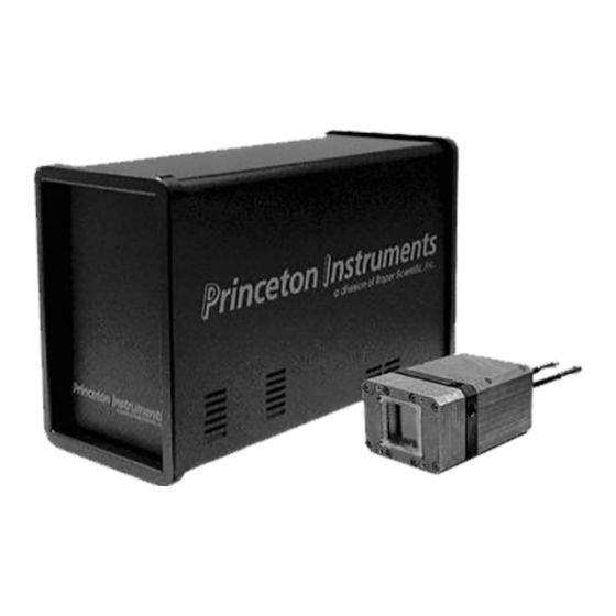
Chapter 2: PI-MTE System Overview This chapter provides information about the PI-MTE Camera and the ST-133 Controller, as well as available accessories and recommended care instructions. PI-MTE Camera The PI-MTE camera is ideally suited for operation inside a vacuum chamber. State-of-the-art CCD arrays are available for the PI-MTE camera that enable outstanding performance in a wide range of X-ray Imaging and Spectroscopy applications. -
Page 14: Controller Connector
ST-133 Controller The ST-133 controller is a compact, high performance CCD Detector Controller for operation with Teledyne Princeton Instruments brand detectors. Designed for high speed and high performance image acquisition, the ST-133 offers data transfer at speeds up to 1 megapixel per second, standard video output for focusing and alignment. -
Page 15: Rear Panel Connectors
Chapter 2 PI-MTE System Overview 2.2.2 Rear Panel Connectors There are three controller board slots. Two are occupied by the plug-in cards that provide various controller functions. The third, covered with a blank panel, is reserved for future development. The left-most plug-in card is the Analog/Control module. Adjacent to it is the Interface Control module. -
Page 16: Rear Panel Connectors And Indicators
PI-MTE System Manual Issue 6 Rear Panel Connectors and Indicators ST-133 rear panel connectors and indicators are illustrated in Figure 2-2. The Fuse/Voltage label is located either above or below the Power Module. Refer to Table 2-1 for descriptions of each connector/indicator. Figure 2-2: ST-133 Rear Panel Connectors and Indicators TTL IN/OUT TEMP... -
Page 17: Table 2-1: St-133 Rear Panel Connectors And Indicators Descriptions
Chapter 2 PI-MTE System Overview Table 2-1: ST-133 Rear Panel Connectors and Indicators Descriptions (Sheet 1 of 2) Label Description Temperature Lock LED Indicates that the temperature control loop has locked and that the temperature of the CCD array will be stable to within ±0.05°C. -
Page 18: Cables
PI-MTE System Manual Issue 6 Table 2-1: ST-133 Rear Panel Connectors and Indicators Descriptions (Sheet 2 of 2) Label Description Remote Shutter Connector Provides shutter-drive pulses for an external shutter. An ST-133 with the 70 V shutter option is required for a camera with the 40 mm shutter. -
Page 19: Interface Card
Chapter 2 PI-MTE System Overview USB 2.0 Interface Cable The standard 16.4 foot (5 m) cable (6050-0494) has USB connectors that interconnect the USB 2.0 connector on the rear of the ST-133 with a USB card installed in the host computer. -
Page 20: Application Software
• PVCAM is the standard software interface for cooled CCD cameras from Teledyne Princeton Instruments. It is a library of functions that can be used to control and acquire data from the camera when a custom application is being written. For example, in the case of Windows, PVCAM is a dynamic link library (DLL). -
Page 21: Optional Components
This is normal and has no effect on operation. 2.11 Repairs Save the original packing materials. Because the PI-MTE camera system contains no user-serviceable parts, repairs must be done by Teledyne Princeton Instruments. Should your system need repair, contact Teledyne Princeton Instruments Customer Support for instructions Refer to... - Page 22 PI-MTE System Manual Issue 6 This page is intentionally blank.
-
Page 23: Installation
Chapter 3: Installation The list and diagrams below briefly describe the sequence of actions required to hookup your system and prepare to gather data. Refer to the specified references for more information. CAUTION! At the first sign of condensation on the camera's inlet and/or outlet pipes, turn off the system. - Page 24 PI-MTE System Manual Issue 6 Action Reference(s) Skip this step for non-vacuum operation. If the camera is Appendix D, Visible to Open to be operated in a vacuum chamber, first replace the Nose Change Instructions, on visible nose with the open nose in a clean room page 103 environment.
- Page 25 Chapter 3 Installation PI-MTE System Diagram...
- Page 26 PI-MTE System Manual Issue 6 This page is intentionally blank.
-
Page 27: System Setup
During the unpacking, check the system components for possible signs of shipping damage. If there are any, notify Teledyne Princeton Instruments and file a claim with the carrier. If damage is not apparent but camera or controller specifications cannot be achieved, internal damage may have occurred in shipment. -
Page 28: System Requirements
PI-MTE System Manual Issue 6 • User Manuals PI-MTE System and WinView/32 Imaging Software. • Host Computer Typically, the computer is user-supplied. • Coolant Circulator Not required by some systems. Typically, the coolant circulator and hoses are user-supplied. System Requirements 4.3.1 Environmental •... -
Page 29: Power
Chapter 4 System Setup • Inlet/Outlet Port Locations VCR male fittings (or Swagelok fittings for earlier systems) and flexible stainless steel hoses are provided to make the hose connections between the camera and an intermediate vacuum flange. The ports are not interchangeable. •... -
Page 30: Verifying Controller Voltage Setting
PI-MTE System Manual Issue 6 • Super VGA monitor and graphics card supporting at least 256 colors with at least 1 MB of memory. Memory requirement is dependent on desired display resolution. • Two-button Microsoft compatible serial mouse or Logitech three-button serial/bus mouse. -
Page 31: Installing The Winview/32 Application Software
Chapter 4 System Setup Installing the WinView/32 Application Software NOTE: Administrator privileges are required under Windows® XP, Windows Vista® and Windows® 7 to install software and hardware. The following installation is performed via the WinView/32 software installation CD. Insert the CD and follow the installation wizard prompts. 2. -
Page 32: Configuring The Usb 2.0 Interface
Large data sets and/or long acquisition times may be subject to data overrun because of host computer interrupts during data acquisition. • USB 2.0 is not supported by the Teledyne Princeton Instruments PC Interface Library (Easy DLLS). • Some WinView 2.5.X features are not fully supported by USB 2.0. Refer to Appendix E, USB 2.0... -
Page 33: Update The Orangeusb Usb 2.0 Driver
Chapter 4 System Setup 4.6.2 Update the OrangeUSB USB 2.0 Driver This procedure is strongly recommended when a laptop computer will be used to communicate with the ST-133. As stated before, we recommend the SIIG, Inc. USB 2.0 PC Card, Model US2246 if USB 2.0 is not native to the laptop's motherboard. To reduce the instances of data overruns and serial violations, the OrangeUSB USB 2.0 Host Controller installed for the SIIG card, should be replaced with the appropriate Microsoft driver (Windows XP, Windows Vista, or Windows 7, depending on the laptop's operating... -
Page 34: Install The Teledyne Princeton Instruments Usb2 Interface
ST-133. Then, turn the ST-133 on before turning on the host computer. 3. At boot up, Windows will detect the Teledyne Princeton Instruments USB2 Interface hardware (i.e., the USB 2.0 Interface Control module.) You may be prompted to... -
Page 35: Connect The Detector-Controller Cable: Non-Vacuum Applications
Chapter 4 System Setup Connect the Detector-Controller Cable: Non-Vacuum Applications Perform this procedure when using the camera in a non-vacuum environment. When operating the camera outside of a vacuum, the camera typically has the visible nose installed. If the visible nose is not installed, refer to Section D.2, Replace the Open Nose with the Visible Nose, on page 106 for installation information. -
Page 36: 4.10 Configure Default Camera System Parameters Into Winview
2. Launch the WinView/32 application. The Camera Detection wizard will automatically run if this is the first time you have installed a Teledyne Princeton Instruments WinView/32 application and a supported camera. 3. Click on the Setup tab and then select the Hardware function. -
Page 37: 4.11 Make The Coolant Connections
Chapter 4 System Setup 5. The Welcome dialog similar to that illustrated in Figure 4-3 is displayed. Figure 4-3: Camera Detection Wizard - Welcome Dialog Verify I will configure the camera system manually is unchecked. If necessary, deselect it. 6. Click Next. 7. -
Page 38: Recommended Flow Rate And Fluid Pressure
PI-MTE System Manual Issue 6 Perform the following procedure to connect coolant hoses: Set up the coolant circulator according to the directions in the user manual for that equipment. Do not apply power to the circulator until directed to do so. 2. -
Page 39: Operation
Chapter 5: Operation The PI-MTE camera family has been designed for mobile operation inside a vacuum chamber. These cameras can be mounted on a movable arm in vacuum to image a subject from more than one direction. Designed for operation with an ST-133 controller, these cameras incorporate a two-stage thermoelectric cooler with heat dissipation to circulating water or other (non-cryogenic) liquid coolant. -
Page 40: Figure 5-1: Block Diagram Of Signal Path In System
PI-MTE System Manual Issue 6 Figure 5-1: Block Diagram of Signal Path in System Whether or not the data is displayed and/or stored depends on the data collection operation (Focus or Acquire) that has been selected in the application software. In WinView, these operations use the Experiment Setup parameters to establish the exposure time (the period when signal of interest is allowed to accumulate on the CCD). -
Page 41: System On/Off Sequences
Chapter 5 Operation System On/Off Sequences If your system is configured for the USB 2.0 communication interface, you must follow the system on/off sequences as stated below. These sequences ensure that communication is established and maintained between the camera and the host computer: The PI-MTE camera must be powered on before WinView/32 is opened to ensure communication between the camera and the computer. -
Page 42: Getting Started
PI-MTE System Manual Issue 6 5.2.2 Getting Started If the system is liquid-cooled, double check that the circulator is filled with a 50:50 mixture of ethylene glycol and water and that the hose connections are secure. When satisfied that these requirements are met, do the following: a. - Page 43 Chapter 5 Operation ► Detector Temperature (Setup Detector Temperature…) +20°C for the First Light procedure. To see when the array temperature reaches and stabilizes at the target temperature, leave the Detector Temperature dialog box open. When the target temperature is reached, the dialog box will report that the Current Temperature has Locked.
-
Page 44: Acquire Data
PI-MTE System Manual Issue 6 5.2.4 Acquire Data If you are using WinView/32, select Focus on the Acquisition menu. Successive images will be sent to the monitor as quickly as they are acquired. Since the camera is shipped without a shutter, the images may smear if the exposure time is short. Figure 5-2 illustrates typical data within WinView. -
Page 45: Powering Down Procedure
Avoid using any corrosive liquid. Set the coolant flow rate to 2 liters/minute. The temperature of the coolant is usually a compromise among a number of competing factors including the camera ambient conditions. Teledyne Princeton Instruments typically uses 10° to 15°C coolant for testing. -
Page 46: Condensation
PI-MTE System Manual Issue 6 5.3.1 Condensation CAUTION! Condensation can cause damage to the camera and will void the warranty. If there are ANY signs of condensation on the camera's coolant pipes, on the CCD, or on the interior CCD window (if so equipped), stop operation immediately and contact the factory for recommended corrective action. -
Page 47: Exposure And Signal
Chapter 5 Operation To prevent condensation damage while the camera is mounted in the vacuum chamber: • Vacuum Chamber: Make sure that the vacuum chamber has been pumped down to at least 1 mTorr, before cooling the camera below ambient or turning on coolant flow. -
Page 48: Figure 5-3: Typical Experiment Setup Dialog
By using one of the signals to synchronize the shutter operation with exposure, the CCD can be read out in darkness. Alternatively, the x-ray source can be interrupted elsewhere in the system while readout is taking place. 1. Please contact your Teledyne Princeton Instruments representative for special applications or requirements. -
Page 49: Temperature Control
Chapter 5 Operation 5.4.3 Temperature Control Lowering the temperature of the CCD will generally enhance the quality of the acquired signal. The temperature is set directly from the application software and it takes from 10-20 minutes for the PI-MTE to reach and lock at the set temperature. The TEMP LOCK indicator on the back of the controller then lights green to indicate that lock has been achieved (for additional information, refer to Section 2.2, ST-133... -
Page 50: Saturation
If you observe a sudden change in the baseline signal you may have excessive humidity in the camera's vacuum enclosure. Immediately turn off the controller. Then, contact Teledyne Princeton Instruments Customer Support for further instructions. Refer to Contact Information page 116 for contact information. -
Page 51: Clean Cycles
Chapter 5 Operation 5.4.6 Clean Cycles As stated before, dark charge integrates on the array whenever the camera is on, whether or not data acquisition is occurring. To minimize the dark charge and other noise in the pixel wells when data acquisition is idle, the Clean Cycles function shifts accumulated charge in a predefined number of rows to the shift register and then discards it. -
Page 52: Continuous Cleans
PI-MTE System Manual Issue 6 5.4.7 Continuous Cleans The Continuous Cleans function is provided when the start of an exposure is tied to an external trigger (i.e., the experiment is being run in External Sync timing mode.) The continuous clean cycles are defined by the same parameter values as the standard clean cycles. -
Page 53: Figure 5-6: Full Frame At Full Resolution
Chapter 5 Operation Readout of the CCD begins with the simultaneous shifting of all pixels one row toward the shift register, in this case the row at the top. The shift register is a single line of pixels along one edge of the CCD, not sensitive to light and used for readout only. Typically the shift register pixels hold twice as much charge as the pixels in the imaging area of the CCD. -
Page 54: Binning
PI-MTE System Manual Issue 6 5.5.2 Binning Binning is the process of adding the data from adjacent pixels together to form a single pixel (sometimes called a super pixel), and it can be accomplished in either hardware or software. Rectangular groups of pixels of any size may be binned together, subject to some hardware and software limitations. -
Page 55: Software Binning
Chapter 5 Operation 5.5.2.2 Software Binning One limitation of hardware binning is that the shift register pixels and the output node are typically only 2-3 times the size of imaging pixels. Consequently, if the total charge binned together exceeds the capacity of the shift register or output node, the data will be lost. -
Page 56: Digitization
PI-MTE System Manual Issue 6 Digitization After gain has been applied to the signal, the Analog-to-Digital Converter (ADC) converts that analog information (continuous amplitudes) into a digital data (quantified, discrete steps) that can be read, displayed, and stored by the application software. The number of bits per pixel is based on both the hardware and the settings programmed into the camera through the software. - Page 57 Each CCD has its own dark charge pattern, unique to that particular device. Every device has been thoroughly tested to ensure its compliance with Teledyne Princeton Instruments' demanding specifications. 2. Do not adjust the offset values to zero or some low-level data will be missed.
- Page 58 PI-MTE System Manual Issue 6 This page is intentionally blank.
-
Page 59: Advanced Topics
Chapter 6: Advanced Topics Previous chapters have discussed setting up the hardware and the software for basic operation. This chapter discusses topics associated with experiment synchronization ► (configured on the Experiment Setup Timing tab page in WinView.) With the exception of Edge Trigger, the topics are addressed in order of their appearance on the Timing tab page illustrated in Figure... -
Page 60: Standard Timing Modes
PI-MTE System Manual Issue 6 Standard Timing Modes Table 6-1 provides information about available timing mode combinations (selected on ► the Experiment Setup Timing tab page). Use this information in combination with the additional information presented within this chapter to determine the optimal timing configuration for an application. -
Page 61: Free Run
Chapter 6 Advanced Topics 6.1.1 Free Run In Free Run mode, the controller does not synchronize with the experiment in any way. The shutter opens as soon as the previous readout is complete, and remains open for the exposure time, t . -
Page 62: External Sync
PI-MTE System Manual Issue 6 6.1.2 External Sync In this mode all exposures are synchronized to an external source via signal input to the Ext Sync BNC on the back of the ST-133. To ensure synchronization, the trigger edge (negative- or positive-going) of the Ext Sync signal must be identified in the application ►... -
Page 63: External Sync With Continuous Cleans
Chapter 6 Advanced Topics PreOpen mode is useful in cases where an External Sync pulse trigger edge cannot be provided 5 – 28 ms (shutter open time) before the actual signal occurs. Its primary drawback is that the CCD is exposed to any ambient light while the shutter is open between frames. -
Page 64: Figure 6-6: Flowchart: Continuous Cleans Operation
PI-MTE System Manual Issue 6 Figure 6-6: Flowchart: Continuous Cleans Operation HUTTER ORMAL HUTTER ONTINUOUSLY LEANED NTIL XTERNAL HUTTER PENS ULSE ECEIVED ONTINUOUSLY LEANED NTIL XTERNAL HUTTER PENS ULSE ECEIVED HUTTER EMAINS REPROGRAMMED XPOSURE YSTEM AITS HILE HUTTER LOSES Once the External Sync pulse trigger edge is received, cleaning of the array stops as soon as the current row is shifted, and frame collection begins: a delay time of up to one row shift can be expected. -
Page 65: Fast And Safe Modes
Chapter 6 Advanced Topics Figure 6-7: Timing Diagram: Continuous Cleans, Negative Edge Trigger Fast and Safe Modes ► The WinView Experiment Setup Timing tab configures Fast Mode or Safe Mode. Figure 6-8 compares the two modes. 6.2.1 Fast Mode In Fast Mode, the ST-133 runs according to the timing of the experiment with no interruptions from the host computer. -
Page 66: Figure 6-8: Flow Chart: Safe Mode Versus Fast Mode
PI-MTE System Manual Issue 6 Figure 6-8: Flow Chart: Safe Mode versus Fast Mode... -
Page 67: Safe Mode
This feature is not supported when the communication protocol is USB 2.0. Teledyne Princeton Instruments’ WinView and WinSpec software packages incorporate WinX32 Automation, a programming language that can be used to automate performing a variety of data acquisition and data processing functions, including use of the TTL In/Out functions. -
Page 68: Figure 6-9: Ttl In/Out Connector Pinout
PI-MTE System Manual Issue 6 Figure 6-9: TTL IN/OUT Connector Pinout TTL IN/OUT Table 6-2: TTL IN/OUT Connector Pinout Pin # Function Pin # Function Pin # Function IN 1 OUT 3 Reserved IN 3 OUT 5 IN 5 OUT 7 OUT 2 IN 7 Reserved... -
Page 69: Ttl In
Chapter 6 Advanced Topics 6.3.1 TTL IN The user controls the eight (8) TTL IN lines by setting them either: • High (+5 V ; TTL 1); • Low (0 V ; TTL 0). When the lines are read, the combination of highs and lows read defines a decimal number which the computer can use to make a decision and initiate actions as specified in the user’s program. -
Page 70: Buffered Vs. Latched Inputs
PI-MTE System Manual Issue 6 Table 6-3: Bit Values with Decimal Equivalents {1 = High; 0 = Low] (Sheet 2 of 2) IN/OUT IN/OUT IN/OUT IN/OUT IN/OUT IN/OUT IN/OUT IN/OUT Decimal Equiv 1=128 1=64 1=32 1=16 6.3.2 Buffered vs. Latched Inputs In controlling the TTL IN lines, users also have the choice of two input line states •... -
Page 71: Ttl Diagnostics Dialog
Chapter 6 Advanced Topics 6.3.4 TTL Diagnostics Dialog WinView/32 provides a TTL Diagnostics dialog that can be used to test and analyze each ► of the TTL IN/OUT lines. To access this dialog, click Hardware Setup Diagnostics. Figure 6-10 for a typical TTL Diagnostics dialog. Figure 6-10: Typical TTL Diagnostics Dialog 6.3.5 Hardware Interface... - Page 72 PI-MTE System Manual Issue 6 Example Suppose you needed to build a cable to monitor the line TTL OUT 1. One approach would be to build a cable assembly as described in the following paragraphs. This procedure could easily be adapted to other situations. Begin with a 25-pin female type D-sub miniature solder type connector (Radio Shack P/N: 276-1548B).
-
Page 73: Chapter 7: Troubleshooting
Chapter 7: Troubleshooting NOTE: Do not attach or remove any cables while the detector system is powered on. Recommended troubleshooting procedures are available for many issues that may occur while working with a PI-MTE system. Refer to Table 7-1 for additional information. -
Page 74: Baseline Signal Suddenly Changes
PI-MTE System Manual Issue 6 Baseline Signal Suddenly Changes In-Vacuum Operation If you observe a sudden change in the baseline signal, turn off the controller. Contact the factory Customer Support Dept. for further instructions. Refer to Contact Information on page 116 for complete information. Out-of-Vacuum Operation If you observe a sudden change in the baseline signal, you may have excessive humidity in the vacuum enclosure of the camera. -
Page 75: Changing The St-133 Line Voltage And Fuses
Chapter 7 Troubleshooting 4. Save the edited file. The next time WinView is launched, the new name will be displayed on the Hardware Setup dialog as illustrated in Figure 7-3. Figure 7-3: Updated Camera Name in Camera Name Field NOTE: If the Camera Detection Wizard is run again at a later time, the name will be changed back to the default name (i.e., Camera1.) -
Page 76: Change Voltage And Fuse Configuration
PI-MTE System Manual Issue 6 7.3.1 Change Voltage and Fuse Configuration WARNING! Before opening the power module, turn the Controller OFF and unplug the power cord. Perform the following procedure to change voltage and fuse configuration: Verify that the power supply is turned OFF and the power cord is unplugged. 2. -
Page 77: Controller Is Not Responding
Chapter 7 Troubleshooting 6. Determine the appropriate fuse rating(s) required by the desired/selected voltage. Refer to Table 7-2 on page 75 or the Fuse/Voltage label located above or below the Power Module. NOTE: If the Controller power switch is on the back of the ST-133, the Fuse/Voltage label is located below the Power Module. -
Page 78: Cooling Troubleshooting
PI-MTE System Manual Issue 6 Cooling Troubleshooting This section provides troubleshooting information for Cooling-related issues. 7.5.1 Camera does not achieve temperature lock If the indicator does not turn green after 30 minutes: • The temperature setting may be at a temperature colder than the specified limit or the environment could be particularly warm. -
Page 79: Camera Loses Temperature Lock
Chapter 7 Troubleshooting 7.5.3 Camera Loses Temperature Lock The internal temperature of the camera is too high. This might occur if: • The operating environment is particularly warm. • You are attempting to operate at a temperature colder than the specified limit. •... -
Page 80: Change The Dma Buffer Setting
PI-MTE System Manual Issue 6 7.7.1 Change the DMA Buffer Setting Perform the following procedure to change the DMA Buffer size configuration: Click OK to dismiss the error dialog. 2. Reboot WinView. 3. Note the array size displayed in the Full Chip dimension field on the ►... -
Page 81: Error Creating Controller Messages
Chapter 7 Troubleshooting Error Creating Controller Messages Figure 7-9 Figure 7-10 illustrate two errors that may be displayed when using the USB 2.0 interface and: • application has not been run; RSConfig.exe • file has become corrupt; or PVCAM.INI • The ST-133 was not turned on before launching WinView/32 and running the Hardware Wizard. -
Page 82: 7.10 Error Occurs At Computer Power Up
PI-MTE System Manual Issue 6 7.10 Error Occurs at Computer Power Up If an error occurs at boot up, either the Interface is not installed properly or there is an address or interrupt conflict. Turn off the computer, try a new address or interrupt and reinstall the card. -
Page 83: Diagnostics Software
Most often, all that is required is a program that will read and report the address and interrupt assignments for each PCI device in the computer. One such program available from Teledyne Princeton Instruments' Customer Support department is called PCICHECK. When the program is run, it reports the address and interrupt assignments for the first PCI device it finds. -
Page 84: Operation
There are no operating considerations that are unique to the PCI Serial card. The card can easily accept data as fast as any Teledyne Princeton Instruments system now available can send it. The incoming data is temporarily stored in the card’s memory, and then transferred to the main computer memory when the card gains access to the bus. -
Page 85: 7.12 Removing/Installing A Plug-In Module
Chapter 7 Troubleshooting 5. Increase the DMA buffer size to a minimum of: • 32 MB; • 64 MB if it is currently 32 MB; • 128 MB if it is currently 64 Mb. 6. Click OK and then close WinView. 7. -
Page 86: Install A Module
PI-MTE System Manual Issue 6 7.12.2 Install a Module Installing a module is a bit more complex because you first have to be sure the locking screws are aligned correctly. Perform the following procedure to install a module: Verify that the Controller has been turned OFF. 2. -
Page 87: 7.13 Secure The Detector-Controller Cable Slide Latch
Troubleshooting 7.13 Secure the Detector-Controller Cable Slide Latch Some Teledyne Princeton Instruments Detector-Controller cables use a slide latch to secure the Detector-Controller cable to the DETECTOR connector on the back of the ST-133. Incorrectly plugging this cable into the connector and improperly securing the slide latch may prevent communication with the PI-MTE (the camera may appear to stop working). -
Page 88: Figure 7-15: Typical Latched Detector Connector
PI-MTE System Manual Issue 6 3. Once the cable is in place, slide the latch down. You may hear a click when the latch locks. See Figure 7-15. Figure 7-15: Typical Latched Detector Connector ULLY LIDE ATCH (LATCHED P OSITION 4. -
Page 89: 7.14 Serial Violations Have Occurred Error
Chapter 7 Troubleshooting 7.14 Serial Violations Have Occurred Error Figure 7-16 illustrates a typical Serial Violations… dialog. Figure 7-16: Typical Serial Violations Have Occurred Dialog This error message dialog will appear if you try to acquire an image or focus the camera and either (or both) of the following conditions exists: •... - Page 90 PI-MTE System Manual Issue 6 This page is intentionally blank.
-
Page 91: Appendix A: Technical Specifications
The following list may not be current. Contact the factory for up-to-date information on available chips and chip performance specifications. Teledyne Princeton Instruments Exclusive: 1340 x 1300B, No AR, MPP, 20 x 20 m pixels e2v CCD42-40: 2048 x 2048B, No AR, MPP, 13.5 x 13.5 m pixels Figure A-1: Typical QE in 1eV –... -
Page 92: Power
PI-MTE System Manual Issue 6 A.1.3 Power Maximum internal heat dissipation in watts: 90 A.1.4 Cooling • –40°C with in-vacuum operation and circulating coolant at +15°C • –25°C with the visible nose and circulating coolant at +15°C. ST-133 ST-133A Dimensions: 5.25 in (13.34 cm) width; 13.63 in (34.62 cm) length; 8.75 in (22.23 cm) height;... -
Page 93: Appendix B: Outline Drawings
Appendix B: Outline Drawings NOTE: Dimensions are in inches [mm]. Figure B-1: PI-MTE Camera (3-01-06 and later) -
Page 94: Figure B-2: Pi-Mte Camera (8-01-05 And Later)
PI-MTE System Manual Issue 6 Figure B-2: PI-MTE Camera (8-01-05 and later) -
Page 95: Figure B-3: Pi-Mte Camera (8-01-05 And Earlier)
Appendix B Outline Drawings Figure B-3: PI-MTE Camera (8-01-05 and earlier) - Page 96 PI-MTE System Manual Issue 6 Figure B-4: ST-133A Controller 8.75 Figure B-5: ST-133B Controller...
-
Page 97: Appendix C: Vcr And Swagelok Fittings
Appendix C: VCR and Swagelok Fittings ® Fittings The VCR fittings are completely assembled and are ready to be connected. Fittings on the PI-MTE coolant pipes are VCR size ¼” male glands with gasket retainer assemblies containing copper gaskets. The flex tubing has female fittings on both ends and the 2¾” ConFlat has male fittings on both ends. -
Page 98: Gasket Replacement Procedure
PI-MTE System Manual Issue 6 3. Using two appropriately sized open-end wrenches, place one wrench on the male fitting and hold it in place while using the second wrench to rotate the female fitting 90º CW. NOTE: For stainless steel or nickel gaskets, rotate 45º CW. Figure C-4. -
Page 99: Swagelok® Fittings
Appendix C VCR and Swagelok Fittings 3. Remove the gasket retaining assembly from the tip of the male fitting. Replace the copper gasket and clip the assembly back onto the fitting. Figure C-7: Remove and Replace Gasket Retaining Assembly 4. Return to Section C.1.1, Installation Procedure, on page 97 to connect the fittings. -
Page 100: High Pressure Applications Or High-Safety-Factor Systems
PI-MTE System Manual Issue 6 3. Hold the fitting body steady with a backup wrench and tighten this nut 1¼ turns. Watch the scribe mark, making one complete revolution and continue to the 9 o’clock position. Figure C-10: Tighten Retaining Nut By scribing the nut at the 6 o’clock position as it appears to you, there will be no doubt as to the starting position. -
Page 101: Figure C-12: Seated Front Ferrule
Appendix C VCR and Swagelok Fittings 2. Insert tubing with pre-swaged ferrules into fitting body until front ferrule seats. See Figure C-12. Figure C-12: Seated Front Ferrule 3. Tighten nut by hand. Rotate nut to the original position with a wrench. See Figure C-13. - Page 102 PI-MTE System Manual Issue 6 This page is intentionally blank.
-
Page 103: Appendix D: Visible To Open Nose Change Instructions
Appendix D: Visible to Open Nose Change Instructions The PI-MTE camera is shipped with a visible nose on the front of the camera. The visible nose typically includes a test lens and is designed to protect the camera during shipment and to allow you to verify system operation in a non-vacuum environment. Because you will probably be using the camera in a vacuum chamber, you will need to replace the visible nose with the open nose before mounting the camera in the chamber. -
Page 104: Figure D-1: Vacuum Valve Location
PI-MTE System Manual Issue 6 Figure D-1: Vacuum Valve Location ACUUM ALVE LASTOMER ASKET 4. After the vacuum has been fully vented, clamp or support the camera with the CCD array looking up. 5. Loosen each of the eight (8) socket head screws on the face of the nose by one turn. -
Page 105: Figure D-3: Remove Nose From Ccd Plane
Appendix D Visible to Open Nose Change Instructions 6. After all eight (8) screws have been loosened one (1) turn, remove all eight (8) screws. 7. Gently rock the nose back and forth to be sure the elastomer gasket has released. CAUTION! Use extreme caution when performing step 8. -
Page 106: Replace The Open Nose With The Visible Nose
PI-MTE System Manual Issue 6 12. Using a criss-cross pattern, tighten each of the eight (8) screws to 15 in-lbs. See Figure D-5 Figure D-5: Tighten Eight (8) Socket Head Screws (8) S IGHT OCKET CREWS 13. Cover the nose opening whenever the camera is not in the vacuum chamber. Replace the Open Nose with the Visible Nose This operation should be performed in a clean room environment to prevent possible contamination of the CCD array. -
Page 107: Figure D-6: Loosen Eight (8) Socket Head Screws
Appendix D Visible to Open Nose Change Instructions Figure D-6: Loosen Eight (8) Socket Head Screws (8) S IGHT OCKET CREWS 4. After each of the eight (8) screws have been loosened one (1) turn, remove the eight (8) screws the rest of the way. 5. -
Page 108: Figure D-8: Install Four (4) Inner Socket Head Screws
PI-MTE System Manual Issue 6 Figure D-7: Elastomer Gasket NNER CREW OLES ON ASKET 8. Very carefully place the visible nose onto the camera. 9. Secure four (4) inner socket head screws that had been previously placed in the nose. See Figure D-8. -
Page 109: Figure D-9: Install Four (4) Corner Socket Head Screws
Appendix D Visible to Open Nose Change Instructions 10. Install the four (4) remaining corner socket head screws. See Figure D-9. Figure D-9: Install Four (4) Corner Socket Head Screws (4) C ORNER OCKET CREWS 11. Using a criss-cross pattern, torque the eight (8) socket head screws to 15 in-lbs. See Figure D-10. -
Page 110: Figure D-11: Vacuum Port Location
PI-MTE System Manual Issue 6 12. Verify that the O-ring seal is in place on the vacuum port adapter and that it is in good condition. 13. Screw the vacuum port adapter into the Vacuum Port on the side of the camera. Figure D-11 Figure D-12. -
Page 111: Appendix E: Usb 2.0 Limitations
Large data sets, and/or long acquisition times, may be subject to data overrun because of host computer interrupts during data acquisition; • USB 2.0 is not supported by the Teledyne Princeton Instruments PC Interface Library (Easy DLLS); • Some WinView 2.5.X features are not fully supported with USB 2.0. Refer to Table E-1 for complete information. - Page 112 PI-MTE System Manual Issue 6 This page is intentionally blank.
-
Page 113: Warranty And Service
(1) year after shipment. During this period, Teledyne Princeton Instruments will repair the product or, at its sole option, repair or replace any defective part without charge to you. You must deliver the entire product to the Teledyne Princeton Instruments factory or, at our option, to a factory-authorized service center. -
Page 114: Sealed Chamber Integrity Limited 12 Month Warranty
(1) year from shipment. Teledyne Princeton Instruments does not warrant that the function of the software will meet your requirements or that operation will be uninterrupted or error free. -
Page 115: Owner's Manual And Troubleshooting
3. All warranty service must be made by the Teledyne Princeton Instruments factory or, at our option, an authorized service center. 4. Before products or parts can be returned for service you must contact the Teledyne Princeton Instruments factory and receive a return authorization number (RMA.) Products or parts returned for service without a return authorization evidenced by an RMA will be sent back freight collect. - Page 116 In no event shall Teledyne Princeton Instruments’ liability exceed the cost of the repair or replacement of the defective product or part.
- Page 117 This page is intentionally blank.
- Page 118 info@princetoninstruments.com USA +1 877-474-2286 | France +33 (1) 60 86 03 65 | Germany +49 (0) 89 660 7793 | UK & Ireland +44 (0) 1628 472 346 Singapore +65 6408 6240 | China +86 10 659 16460 | Japan +81 (3) 5639 2741...
Need help?
Do you have a question about the Princeton Instruments PI-MTE and is the answer not in the manual?
Questions and answers