
Related Manuals for Teledyne Princeton Instruments Nano-XF


Summary of Contents for Teledyne Princeton Instruments Nano-XF
- Page 1 Nano-XF System Manual 4411-0116 Issue 5 October 4, 2019 www.princetoninstruments.com...
- Page 2 Trenton, NJ 08619 TEL: 800-874-9789 / 609-587-9797 No part of this publication may be reproduced by any means without the written permission of Teledyne Princeton Instruments. Printed in the United States of America. Camera Link is a registered trademark of the Automated Imaging Association.
-
Page 3: Table Of Contents
Table of Contents Chapter 1: Introduction ..........7 Package Contents . - Page 4 Nano-XF System Manual Issue 5 6.2.2 Mode 1: Level Triggering........31 6.2.2.1 Asynchronous Reset with Pulse Width Controlled Integration .
- Page 5 Issue 5 List of Figures List of Figures Figure 2-1: Typical Nano-XF Camera with Camera Controller ....9 Figure 2-2: Typical Nano-XF System Components ......11 Figure 2-3: MegaPlus Multi-Head Controller Front Panel .
- Page 6 Nano-XF System Manual Issue 5 This page is intentionally blank.
-
Page 7: Introduction
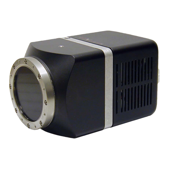
Chapter 1: Introduction Congratulations on your purchase of the Teledyne Princeton Instruments Nano-XF: 11000 camera system. This advanced design based on Teledyne Princeton Instruments' cooling technology offers up to +10 °C cooling with air. The unique camera design with the fiberoptic extended outside the vacuum offers outstanding flexibility for optimizing system performance at any x-ray energy. -
Page 8: Camera Control And Image Acquisition - Camera Link
Nano-XF System Manual Issue 5 Camera Control and Image Acquisition - Camera Link® The Nano-XF imaging system incorporates a standard Camera Link interface for interfacing to industry-standard frame grabbers. The Camera Link Frame grabber interface provides a high bandwidth connection for image acquisition as well as an interface for camera control. -
Page 9: Chapter 2: Nano-Xf Camera System
Chapter 2: Nano-XF Camera System All standard Nano-XF:11000 systems include a multi-head MegaPlus Camera Controller and an EPIX PIXCI frame grabber board with EPIX XCAP software or a National Instruments PCIe 1427 frame grabber with NI-IMAQ software. Nano-XF cameras and controllers contain very low noise, high dynamic range CCD electronics with 12-bit digitalization. -
Page 10: Table 2-1: Camera Models & Performance Specifications
Nano-XF System Manual Issue 5 • Camera Settings Read/Write Allows the camera to save its current operating parameters to internal, non-volatile memory within the Camera Controller. A set number is used as an identifier for the record. The record of saved operating parameters can then be applied to the camera. -
Page 11: Standard System Components
Fiber Optic The Nano-XF fiberoptic tapers are bonded to the face of the CCD arrays with Teledyne Princeton Instruments' fiberoptic-coupling technology. The direct bonding to the face of the array eliminates the need for an intermediate fiberoptic faceplate or an oil layer between surfaces, thereby increasing sensitivity. -
Page 12: Camera Connectors
Nano-XF System Manual Issue 5 2.2.1.1 Camera Connectors • TO CONTROLLER (Camera-Controller) Control signals and data are transmitted between the camera and the front panel of the MegaPlus controller via the 18-pin TO CONTROLLER port located on the rear of the camera. •... -
Page 13: Megaplus® Multi-Head Controller
Chapter 2 Nano-XF Camera System MegaPlus® Multi-Head Controller Front Panel The camera connects to the camera controller via factory supplied cables. The controller has four Remote Head 18-pin connectors. CAUTION! Make sure the controller power switch (on the rear) is at the OFF position before connecting the cables! NOTE: Due to the high resolution of the Nano-XF camera, only one... -
Page 14: Cables
Nano-XF System Manual Issue 5 • Green LED When lit, indicates a camera is connected to the controller. After initialization is complete (about 30-45 seconds,) the LED will blink at a steady rate of about 1 blink/second. This indicates that the camera is ready to acquire data. •... -
Page 15: Certificate Of Performance
Certificate of Performance Each Nano-XF camera has a Certificate of Performance. This certificate states that the camera system was assembled and tested according to approved Teledyne Princeton Instruments’ procedures. It documents the camera performance data as measured during the testing of your Nano-XF and lists the Sales Order, Purchase Order, and Camera Serial numbers which are useful when contacting Teledyne Princeton Instruments’... - Page 16 Nano-XF System Manual Issue 5 This page is intentionally blank.
-
Page 17: Chapter 3: Installation Overview
Chapter 3: Installation Overview This chapter provides the procedure and block diagram required to set up the Nano-XF and prepare to gather data. Broadly speaking, you will need to: • Check your package contents to ensure you have all of the necessary components. -
Page 18: Figure 3-1: Block Diagram: Nano-Xf:11000 System, Camera Link
Nano-XF System Manual Issue 5 Figure 3-1 illustrates a typical Nano-XF system block diagram. Figure 3-1: Block Diagram: Nano-XF:11000 System, Camera Link... -
Page 19: Chapter 4: Epix/Pixci Installation
Chapter 4: EPIX/PIXCI Installation XCAP-Lite is supplied with each PIXCI imaging board and allows access to PIXCI imaging board(s). XCAP-Lite is a free version of the XCAP software and does not require an authorization key. Selected image processing and analysis functions are disabled, but you can use this software to confirm system operation, acquire images, and perform limited image analysis while the PIXCI imaging board is present and open for use. -
Page 20: Xcap-Std/Plus Software Installation
Nano-XF System Manual Issue 5 XCAP-Std/Plus Software Installation If the computer is set to allow automatic execution of a loaded CD, the interactive index program will start automatically. Otherwise, execute the index program from a command prompt, or via the ►... -
Page 21: Pixci Board Installation
Chapter 4 EPIX/PIXCI Installation PIXCI Board Installation Make sure that the computer is turned off. 2. Remove the cover and install the PIXCI imaging board. 3. Replace the cover and turn on the computer. 4. Restart Windows. The Welcome To Found New Hardware Wizard is displayed. a. -
Page 22: Camera Installation And Setup
Nano-XF System Manual Issue 5 Camera Installation and Setup Connect the following Camera/Controller cables: • Connect the Camera Link cable to: — Camera Link 1 on the controller; — Port 1 on the PIXCI board NOTE: Port 1 is on the right when looking at the computer from the back. -
Page 23: Chapter 5: National Instruments Installation
Chapter 5: National Instruments Installation Minimum System Requirements The development computer must satisfy the following minimum requirements to run National Instruments Vision Acquisition Software: ® • Pentium 4, 1 GHz or equivalent processor; • 512 MB RAM; • Free hard disk space: —... -
Page 24: Pcie 1427 Frame Grabber Installation And Ni-Imaq Configuration
Nano-XF System Manual Issue 5 PCIe 1427 Frame Grabber Installation and NI-IMAQ Configuration Perform the following procedure to install the PCIe 1427 frame grabber and configure NI IMAQ: CAUTION! Power off and unplug the host computer before installing the hardware. Wait for any motherboard LEDs to power off before proceeding, since some computers remain powered for some time after being unplugged. -
Page 25: Configuring A Remote Xi/Compact Pcie Image Acquisition Device
Chapter 5 National Instruments Installation c. To change the camera settings, modify the parameters at the bottom of the image viewer panel. d. Acquire an image in the following ways: • Use the Snap button to acquire and display a single image with the image acquisition device. - Page 26 Nano-XF System Manual Issue 5 This page is intentionally blank.
-
Page 27: Chapter 6: Operation Modes
Chapter 6: Operation Modes Data acquisition and the transfer of a single frame of data is initiated by a trigger signal from some trigger source, previously selected via a camera control function. The source of the trigger can be an external electrical pulse (Trigger state is ON) or the trigger will be generated within the Controller (Trigger state is OFF). -
Page 28: Available Trigger Modes (Trigger State Is On)
Nano-XF System Manual Issue 5 Available Trigger Modes (Trigger State is ON) Triggered acquisition can be configured for a variety of different operating modes. These triggered modes provide different methods of controlling the start of image acquisition and the duration of the integration time. When the trigger state is OFF, the camera is in continuous, free run or "video mode."... -
Page 29: Mode 0 Timing Parameters
Chapter 6 Operation Modes 6.2.1.4 Mode 0 Timing Parameters Figure 6-3 Figure 6-4. Figure 6-3: Timing Diagram: Mode 0, Triggering with No Strobe Delay Figure 6-4: Timing Diagram: Mode 0, Triggering with Strobe Delay • (Clear Start Latency) This 2 s interval defines the delay from the receipt of trigger to the start of the Clear Pulse to the sensor. -
Page 30: Table 6-2: Mode 0: Typical Clear Pulse Time (T Cp )
Nano-XF System Manual Issue 5 • (Clear Pulse) This is the time it takes to clear the sensor. The start of Clear Pulse begins as soon as possible after the camera receives a trigger (after T This time is sensor dependent. There is a nominal uncertainty in the start latency of ±... -
Page 31: Mode 1: Level Triggering
Chapter 6 Operation Modes • (Recovery Time) This interval represents the time from the end of sensor readout to the time the system can accept another trigger pulse. The recovery time is approximately 1 • Maximum Trigger Rate The Maximum Trigger Rate is related to the minimum time between triggers which may be calculated as: read 6.2.2... -
Page 32: Mode 1 Timing Parameters
Nano-XF System Manual Issue 5 Figure 6-6: Timing Diagram: Mode 1, Triggering with No Strobe Delay 6.2.2.4 Mode 1 Timing Parameters • (Clear Start Latency) This 2 s interval defines the delay from the receipt of trigger to the start of the Clear Pulse to the sensor. -
Page 33: Table 6-7: Mode 1: Typical Transfer Time (T Xfr )
Chapter 6 Operation Modes • (Transfer Time) This interval represents the time it takes to transfer data from the photosites to the vertical shift register. This time is sensor dependent. Refer to Table 6-4 for typical values. Table 6-7: Mode 1: Typical Transfer Time (T Sensor Sensor Frequency ... -
Page 34: Mode 6: Periodic Interval Triggering
Nano-XF System Manual Issue 5 6.2.3 Mode 6: Periodic Interval Triggering This section provides information about Mode 6 operation. 6.2.3.1 Self-Trigger Overview When the camera is in trigger periodic interval mode, the camera self-triggers on a repeated cycle as long as the trigger mode is enabled. The interval is a user-defined value. -
Page 35: Table 6-9: Mode 6: Typical Start Latency Time (T Cp )
Chapter 6 Operation Modes • (Start Latency) This is the time from the leading edge of the trigger pulse to the start of the integration period. The start latency is equal to the time it takes to clear the sensor. This time is sensor dependent. -
Page 36: Retriggering
Nano-XF System Manual Issue 5 Retriggering If a second trigger arrives before the processing of the first trigger has been completed, there are two possible responses by the camera. The camera's response depends on when in the triggering process the second trigger arrives. The maximum trigger rate constraints must not be violated. -
Page 37: Appendix A: Bit Windowing Overview
Appendix A: Bit Windowing Overview The bit window feature in Nano-XF camera allows the selection of which bits (8-bit or 10-bit) are output from the 12-bit range digitization of the image. Figure A-1 illustrates is an example where 8-bit output is selected. Various bit windows are selected by determining whether the start bit is 0, 1, 2, 3, or 4. - Page 38 Nano-XF System Manual Issue 5 This page is intentionally blank.
-
Page 39: Appendix B: Specifications
Appendix B: Specifications This appendix provides information about camera characteristics, dimensions, and mounting. Nano-XF:11000 Refer to Table B-1 for Nano-XF:11000 specifications. Table B-1: Nano-XF:11000 Camera Specifications (Sheet 1 of 2) Category Specification Sensor Model KAI-11002 Sensor Type Solid State Interline Transfer Progressive Scan CCD Resolution 4008 (H) x 2672 (V) ... -
Page 40: Figure B-1: Kai-11002 Mono Quantum Efficiency
Nano-XF System Manual Issue 5 Table B-1: Nano-XF:11000 Camera Specifications (Sheet 2 of 2) Category Specification Max. integration time >120 s Sensor Output Sensitivity Shuttering Electronic Max Frame Rate w/ 2x2 binning 8.17 FPS @ 30 MHz Max Frame Rate w/ 3x3 binning 10.98 FPS @ 30 MHz Max Frame Rate w/ 4x4 binning 13.23 FPS @ 30 MHz... -
Page 41: Multi-Head Controller
Appendix B Specifications Multi-Head Controller Refer to Table B-2 for multi-Head controller characteristics. Table B-2: Multi-Head Controller Characteristics Category Specifications Camera Inputs Controller Data Interface Camera Link Serial, IEEE 1394 RS-232 Image Data Interface Camera Link (medium) IEEE 1394 Camera Link Ports Base and Medium/Dual Base Output bit Depth 8, 10, or 12 per channel... -
Page 42: Connectors
Nano-XF System Manual Issue 5 Connectors This section provides information about connectors, including pin outs. B.3.1 Camera Link MDR Connector The Camera Link serialized frame grabber interface is compliant with the industry standard Camera Link Specification. This specification is available on the Automated Imaging Association website (www.visiononline.org/). -
Page 43: Power Connector
Appendix B Specifications B.3.2 Power Connector The Camera Controller has a LEMO elbow receptacle, EPG.0B.302.HLN for 12 V power input. This receptacle mates with the FGG.0B.302.CLAD56 plug. Pin 1 is 12 V and Pin 2 is connected to ground. For more information about the LEMO connectors, visit www.lemousa.com... - Page 44 Nano-XF System Manual Issue 5 This page is intentionally blank.
-
Page 45: Appendix C: Outline Drawings
Appendix C: Outline Drawings Figure C-1: Outline Drawing: Nano-XF:11000... -
Page 46: Figure C-2: Outline Drawing: Megaplus Multi-Head Controller
Nano-XF System Manual Issue 5 Figure C-2: Outline Drawing: MegaPlus Multi-Head Controller... -
Page 47: Appendix D: Glossary
Appendix D: Glossary Bit Depth/Bit Window Selection Enables users to select the bit-depth of data output from the camera. All internal data is 12 bits per image. When bit depths less than 12 bits are selected, the least significant bit can be specified in order to select which of the 12 available bits is output, creating a Bit Window. - Page 48 Nano-XF System Manual Issue 5 Trigger (Trigger-In) An external signal to control when an image is acquired. The controller provides a variety of trigger modes. Trigger logic can be specified as negative or positive. Trigger signals can be sourced from the connector on the rear panel of the controller or when available, through the frame grabber cable.
-
Page 49: Fcc Declaration
FCC Declaration This equipment has been tested and found to comply with the limits for a Class B digital device, pursuant to Part 15 of the FCC Rules. These limits are designed to provide reasonable protection against harmful interference in a residential installation. This equipment generates, uses, and can radiate radio frequency energy and, if not installed and used in accordance with the instructions, may cause harmful interference to radio communications. - Page 50 Nano-XF System Manual Issue 5 This page is intentionally blank.
-
Page 51: Warranty And Service
(1) year after shipment. During this period, Teledyne Princeton Instruments will repair the product or, at its sole option, repair or replace any defective part without charge to you. You must deliver the entire product to the Teledyne Princeton Instruments factory or, at our option, to a factory-authorized service center. -
Page 52: Sealed Chamber Integrity Limited 12 Month Warranty
(1) year from shipment. Teledyne Princeton Instruments does not warrant that the function of the software will meet your requirements or that operation will be uninterrupted or error free. -
Page 53: Owner's Manual And Troubleshooting
3. All warranty service must be made by the Teledyne Princeton Instruments factory or, at our option, an authorized service center. 4. Before products or parts can be returned for service you must contact the Teledyne Princeton Instruments factory and receive a return authorization number (RMA.) Products or parts returned for service without a return authorization evidenced by an RMA will be sent back freight collect. -
Page 54: Contact Information
In no event shall Teledyne Princeton Instruments’ liability exceed the cost of the repair or replacement of the defective product or part. - Page 55 This page is intentionally blank.
- Page 56 info@princetoninstruments.com USA +1 877-474-2286 | France +33 (1) 60 86 03 65 | Germany +49 (0) 89 660 7793 | UK & Ireland +44 (0) 1628 472 346 Singapore +65 6408 6240 | China +86 10 659 16460 | Japan +81 (3) 5639 2741...
Need help?
Do you have a question about the Princeton Instruments Nano-XF and is the answer not in the manual?
Questions and answers