
Related Manuals for Teledyne Princeton Instruments Quad-RO


Summary of Contents for Teledyne Princeton Instruments Quad-RO
- Page 1 Quad-RO System Manual 4411-0114 Issue 5 October 22, 2019 www.princetoninstruments.com...
- Page 2 Trenton, NJ 08619 TEL: 800-874-9789 / 609-587-9797 No part of this publication may be reproduced by any means without the written permission of Teledyne Princeton Instruments. Printed in the United States of America. FireWire is a trademark of Apple Computer, Inc., registered in the U.S. and other countries.
-
Page 3: Table Of Contents
Beryllium Window ..........15 1.14 Teledyne Princeton Instruments Customer Service ......15 Chapter 2: System Components . - Page 4 Quad-RO System Manual Issue 5 System Requirements ..........26 4.3.1 Environmental .
- Page 5 Issue 5 Table of Contents Chapter 6: Advanced Topics ..........59 Timing {Trigger Response} Modes .
- Page 6 Quad-RO System Manual Issue 5 Appendix E: CCD Coverage: 165 mm Taper ......105 Appendix F: WinX/32 to LightField Term Cross Reference .
- Page 7 Issue 5 List of Figures Figure 6-2: Free Run {No Response} Shutter Actions ......61 Figure 6-3: Timing Diagram: Free Run .
- Page 8 Quad-RO System Manual Issue 5 List of Tables Revision History ..........2 Table 3-1: Quad-RO Installation Actions .
-
Page 9: Introduction
Shutterless operation, low noise, and the ability to select a fiber ratio up to 5:1 make the Teledyne Princeton Instruments Quad-RO system an ideal choice for both of these applications. -
Page 10: Software Solutions
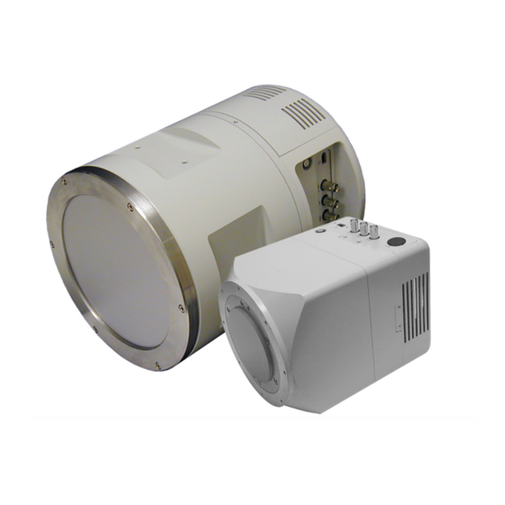
PICam, a 64-bit library, is available for writing your own software. Quad-RO System Components The Teledyne Princeton Instruments Quad-RO system normally contains the major components shown in Figure 1 and described below. Actual system components will depend on the system configuration ordered. -
Page 11: About This Manual
Chapter 1 Introduction • CD-ROM This CD contains the WinView/32 or LightField imaging software and related manuals in PDF format. • Interface Card User-supplied FireWire™ (IEEE 1394a) Interface Card. • Interface Cable FireWire (IEEE 1394a) cable: 14.7 feet [4.5 m] cable (6050-0558) is standard. Figure 1-1: Standard System Components About this Manual... -
Page 12: Manual Organization
Quad-RO System Manual Issue 5 1.7.2 Manual Organization The following chapters and appendices are included in this manual: • Chapter 1, Introduction Briefly describes the Quad-RO family of cameras; details the structure of this manual; and documents environmental, storage, and cleaning requirements. •... -
Page 13: Safety Related Symbols Used In This Manual
WARNINGS! If the Quad-RO camera system is used in a manner not specified by Teledyne Princeton Instruments, the protection provided by the equipment may be impaired. 2. If the equipment is damaged, the protective grounding could be disconnected. Do not use damaged equipment until its safety has been verified by authorized personnel. -
Page 14: 1.10 Repairs
Issue 5 1.10 Repairs Repairs must be done by Teledyne Princeton Instruments. If your system hardware needs repair, contact Teledyne Princeton Instruments Customer Service. Please save the original packing material so you can safely ship the system to another location or return it for repairs. -
Page 15: 1.13 Cleaning
To clean the window, wipe it down with isopropanol and a lint free cloth. DO NOT use water. Beryllium is highly susceptible to localized pitting when in contact with the chloride and sulfate ions contained in ordinary water. 1.14 Teledyne Princeton Instruments Customer Service Refer to Contact Information... - Page 16 Quad-RO System Manual Issue 5 This page is intentionally blank.
-
Page 17: System Components
Fiber Optics The Quad-RO fiberoptic tapers are bonded to the face of the CCD arrays with Teledyne Princeton Instruments' proprietary fiberoptic-coupling technology. The direct bonding to the face of the array eliminates the need for an intermediate fiberoptic faceplate or an oil layer between surfaces, thereby increasing sensitivity and resolution. -
Page 18: Connectors
Quad-RO System Manual Issue 5 Electronics The camera electronics enclosure contains array driver, preamplifiers, ADCs and all control logic for a fully self-contained electronic solution. The speed of data acquisition is determined primarily by the A/D converter used, the selected readout rate (1 MHz or 500 kHz), and the mode (four-port or single-port). -
Page 19: Coolant Ports
Chapter 2 System Components • READY 0-+3V logic level output (TTL-compatible) provides a 50 mA closure to ground when active, open when inactive. Allows data acquisition and readout to be synchronized with external events. • Power Depending on operating conditions, approximately 200 W maximum total power is drawn from the Quad-RO power supply. -
Page 20: Cables
The cable connects the power supply to the camera. User Manuals Quad-RO System Manual This manual describes how to install and use the Quad-RO system components. The most up-to-date version of this manual and other Teledyne Princeton Instruments manuals can be downloaded from: ftp://ftp.princetoninstruments.com/Public/Manuals/Princeton Instruments... -
Page 21: Optional Items
WinView/32 also features snap-ins and macro record functions to permit easy user customization of any function or sequence. PVCAM The standard 32-bit software interface for cooled CCD cameras from Teledyne Princeton Instruments. This is a library of functions that can be used to control and acquire data from the camera when a custom application is being written. -
Page 22: Coolant Circulator
Quad-RO System Manual Issue 5 PICam The standard 64-bit software interface for cooled CCD cameras from Teledyne Princeton Instruments. PICam is an ANSI C library of camera control and data acquisition functions. Currently, the interface supports Windows Vista and Windows 7. -
Page 23: Initial System Verification
Chapter 3: Initial System Verification Table 3-1 lists the sequence of actions required to install a Quad-RO system and prepare to gather data. Refer to the indicated references for additional information. Refer to Figure 3-1, on page 24 for a high-level block diagram for a typical system. Table 3-1: Quad-RO Installation Actions (Sheet 1 of 2) Action... -
Page 24: Figure 3-1: System Block Diagram: Quad-Ro System
Quad-RO System Manual Issue 5 Table 3-1: Quad-RO Installation Actions (Sheet 2 of 2) Action Refer to… 12. Set the target array temperature. Chapter 5 Operation: page 31 for WinView/32, page 33 for LightField 13. When the system reaches temperature lock, begin acquiring Chapter 5 Operation, data in Focus {Preview} mode. -
Page 25: System Setup
During the unpacking, check the system components for possible signs of shipping damage. If there are any, notify Teledyne Princeton Instruments and file a claim with the carrier. If damage is not apparent but camera or controller specifications cannot be achieved, internal damage may have occurred in shipment. -
Page 26: System Requirements
Quad-RO System Manual Issue 5 System Requirements 4.3.1 Environmental • Operating temperature: 0°C to +40°C; • Operating temperature range over which system specifications can be met: 0°C to +25°C; ≤ • Relative humidity 50% non-condensing. 4.3.2 Ventilation • Camera: Allow at least one inch of clearance for side and rear air vents. 4.3.3 Vacuum The CCD is housed in the vacuum with the fiberoptic taper extending beyond the... -
Page 27: Power
Chapter 4 System Setup 4.3.5 Power • Camera The camera receives its power from the Quad-RO power supply, which in turn plugs into a source of AC power. CAUTION! The plug on the line cord supplied with the system should be compatible with the line-voltage outlets in common use in the region to which the system is shipped. -
Page 28: Mount The Camera
Quad-RO System Manual Issue 5 4.3.7 Mount the Camera For the square case camera, there are three threaded camera mounting holes on the bottom of the camera, toward the rear. • Two holes are M8 x 1.25 tap (0.75” deep); •... -
Page 29: Install Application Software
Chapter 4 System Setup Install Application Software NOTE: Administrator privileges are required under Windows XP, Windows Vista and Windows 7 to install software and hardware. 4.4.1 WinView/32 Software The following installation is performed via the WinView/32 software installation CD. Insert the CD and follow the installation wizard prompts. 2. -
Page 30: Lightfield Software
Quad-RO System Manual Issue 5 4.4.2 LightField Software The following installation is performed via the LightField software installation CD. Before starting the installation: • Verify that the computer operating system is Windows Vista (64-bit) or Windows 7 (64-bit). • Confirm that your computer has a functioning FireWire (1394a) port. •... -
Page 31: Configure A Firewire (Ieee 1394A) Interface
2. Run the WinView/32 application. If this is the first time you have installed a Teledyne Princeton Instruments WinView/32 application and a supported camera, the Camera Detection wizard will automatically run. Perform the following procedure: a. -
Page 32: Figure 4-6: Typical Winview/32 Camera Detection Wizard - Welcome
Quad-RO System Manual Issue 5 3. On the Welcome dialog, leave the checkbox unselected and click Next >. Figure 4-6. Figure 4-6: Typical WinView/32 Camera Detection Wizard - Welcome Dialog 4. Follow the instructions on the dialogs to perform the initial hardware setup. This wizard enters default parameters on the Hardware Setup dialog tabs and gives you an opportunity to acquire a single test image to confirm the system is working. -
Page 33: Lightfield
Chapter 4 System Setup 4.6.2 LightField Make sure the Quad-RO is connected to the host computer and that the camera power supply is turned on. 2. Start LightField. 3. While LightField is starting up, it will detect the available device(s) and load the appropriate icons into the Available Devices area in the Experiment workspace. -
Page 34: Make The Circulator-Camera Connections
Quad-RO System Manual Issue 5 4.6.3 Make the Circulator-Camera Connections Set up the coolant circulator according to the directions in the user manual for that equipment. Do not apply power to the circulator until directed to do so. 2. Make the hose connections between the circulator and the camera. For best cooling performance, the tubing should be no longer than necessary. -
Page 35: Operation
Chapter 5: Operation Once the Quad-RO camera has been installed, camera operation is basically straightforward. In most applications you simply establish the optimum setup using the Focus {Preview} mode, set the target detector temperature, wait until the temperature has stabilized at the set temperature (refer to Section 5.5.3.1, Setting the Temperature, on page 45 for additional information,) and then do actual data acquisition in the... -
Page 36: System On/Off Sequences
Quad-RO System Manual Issue 5 Whether or not the data is displayed and/or stored depends on the data collection operation (Focus or Acquire) that has been selected in the application software. In WinView/32, these operations use the Experiment Setup parameters to establish the exposure time (the period when signal of interest is allowed to accumulate on the CCD). -
Page 37: First Light For Winview/32
Chapter 5 Operation 3. Powering the camera OFF: • WinView/32 Must be closed before powering the camera OFF. If you power the camera OFF before closing WinView/32, the communication link with the camera will be broken. You should close WinView/32 immediately. If the camera is disconnected and then reconnected, it is not safe to continue running the WinView/32 software: you should close the software and restart it. -
Page 38: Configure Parameters
Quad-RO System Manual Issue 5 5.2.2 Configure Parameters NOTE: The following procedure is based on WinView/32: you will need to modify it if you are using a different application. Basic familiarity with the WinView/32 software is assumed. If this is not the case, you may want to review the software manual or have it available while performing this procedure. -
Page 39: Acquiring Data
Chapter 5 Operation ► • Experiment Setup Main tab (Acquisition Experiment Setup…) — Exposure Time: 100 ms; — Accumulations & Number of Images: 1; — CCD Readout: Use Full Chip; ► • Experiment Setup Timing tab (Acquisition Experiment Setup…) — Timing Mode: Free Run; —... -
Page 40: First Light For Lightfield
Quad-RO System Manual Issue 5 This completes First Light for WinView/32. If the system functioned as described, you can be reasonably sure it has arrived in good working order. In addition, you should have a basic understanding of how the system hardware is used. REFERENCES: Refer to Section 5.4, Circulator Power Down... -
Page 41: Configure Parameters
Chapter 5 Operation 5.3.2 Configure Parameters NOTE: The following procedure is based on LightField. Basic familiarity with the LightField software is assumed. If this is not the case, you may want to review the software manual or have it available while performing this procedure. After LightField opens, you should see an icon representing your camera in the Available Devices area. -
Page 42: Acquire Data
Quad-RO System Manual Issue 5 Figure 5-4: Typical LightField Experiment Devices Area 5.3.3 Acquire Data Click on the View tab, just above Experiment Devices, to change to the display area. Figure 5-5. Figure 5-5: Typical LightField View Area... -
Page 43: Figure 5-6: Typical Lightfield View Area Displaying An Image
Chapter 5 Operation 2. Click on the Run button to start Preview mode. In this mode, images will be continuously acquired and displayed. See Figure 5-6. Figure 5-6: Typical LightField View Area Displaying an Image 3. Successive images will be sent to the monitor as quickly as they are acquired. Since no X-ray source is being used, the acquired images will be of the camera's dark charge. -
Page 44: Circulator Power Down Procedure
Quad-RO System Manual Issue 5 Circulator Power Down Procedure It is recommended that the camera warm up be carefully controlled. Proper warm up will be achieved by proceeding as follows: While running the application software, allow the camera to warm up from its current locked temperature to ambient temperature. -
Page 45: Ccd Temperature
Chapter 5 Operation 5.5.3 CCD Temperature Each Quad-RO camera contains a Peltier-effect thermoelectric cooler that cools the CCD. This cooling, assisted by liquid coolant circulation, reduces the amount of dark charge that is generated on the array. A thermal sensor attached to the cooling block of the camera monitors the array temperature and the current temperature is reported back to the operating software. -
Page 46: Dark Charge
Immediately turn off the system. Refer to Appendix D, Restore the Vacuum, on page 101 and contact Teledyne Princeton Instruments Customer Support for assistance. Refer to Contact Information on page 114 for complete information. -
Page 47: Readout
Chapter 5 Operation Readout After the exposure time has elapsed, the charge accumulated in the pixels needs to be read out of the array, digitized, and transmitted to the application software where it can be displayed and/or stored. Readout begins by moving charge from the CCD image area to the shift register(s): charge from the array will be read out from four ports simultaneously or, in the case of the Quad-RO:4096, it may be read out from a single factory-selected port (four-port or single-port readout for Quad-RO:4096 cameras... -
Page 48: Full Frame Readout
Quad-RO System Manual Issue 5 5.6.1 Full Frame Readout In this section, a simple 16 x 16 pixel CCD is used to demonstrate how charge is shifted and digitized using four-port operation. Full frame readout, for full frame CCDs, reads out the entire CCD surface at the same time. -
Page 49: Partial Frame Roi With Four-Port Readout
Chapter 5 Operation After one row from each half (top and bottom) of the array is moved into the shift registers, the charge is shifted toward the output nodes, located at each end of each shift register. As each value is "emptied" into the output it is digitized. Only after all pixels in the first pair of rows are digitized is the second pair of rows moved into the shift registers. -
Page 50: Define A Symmetrical Partial Frame Roi For Four-Port Readout
Quad-RO System Manual Issue 5 5.6.2.1 Define a Symmetrical Partial Frame ROI for Four-Port Readout This section describes how to calculate the X , and Y coordinates for start start an ROI that is symmetrical about the center of the CCD. These values are required to configure the ROI in the data acquisition software. -
Page 51: Figure 5-11: 4096 X 4096 Ccd With Symmetrical 2048 X 1024 Region
Chapter 5 Operation For example, when configuring an ROI using WinX/32, Figure 5-11 illustrates a 4096 x 4096 CCD where a symmetrical 2048 x 1024 Region of Interest is to be defined. Figure 5-11: 4096 x 4096 CCD with Symmetrical 2048 x 1024 Region of Interest The four coordinates for this ROI are calculated as follows: ... -
Page 52: 4096 Only)
Quad-RO System Manual Issue 5 5.6.3 Partial Frame ROI with Single-Port Readout (Quad-RO:4096 only) For Quad-RO:4096 cameras with 1:1 fiberoptic tapers, single-port readout will be used whenever an ROI does not meet the symmetrical and centered rules. Figure 5-12 shows a 12 x 8 ROI where the ROI is not symmetrical about the center and the middle (dashed lines). -
Page 53: Binning
Chapter 5 Operation 5.6.4 Binning Binning is the process of adding the data from adjacent pixels together to form a single pixel (sometimes called a super pixel), and it can be accomplished in either hardware or software. The choice or hardware or software binning is made on the Experiment ►... -
Page 54: Software Binning
Quad-RO System Manual Issue 5 5.6.4.2 Software Binning One limitation of hardware binning is that the shift register pixels and the output node are typically only two-to-three times the size of imaging pixels. Consequently, if the total charge binned together exceeds the capacity of the shift register or output node, data accuracy will be lost. -
Page 55: Winview: Define A Binned Roi For Four-Port Readout
Chapter 5 Operation 5.6.4.3 WinView: Define a Binned ROI for Four-Port Readout To ensure four-port readout, you must adhere to the following rules when setting up for binning (hardware or software): NOTE: The binned ROI must be centered horizontally and vertically on the CCD and it must have an even number of pixels or super pixels in the X and Y dimensions. -
Page 56: Lightfield: Define A Binned Roi For Four-Port
Quad-RO System Manual Issue 5 5.6.4.4 LightField: Define a Binned ROI for Four-Port Readout To ensure four-port readout, you must adhere to the following rules when setting up for binning (hardware or software): NOTE: The binned ROI must be centered horizontally and vertically on the CCD. -
Page 57: Analog Gain
Chapter 5 Operation 6. If the ROI does not meet the ROI definition requirements, its outline will turn red and the edit box(es) containing value(s) that need to be adjusted will also be outlined in red. To correct any problems: •... -
Page 58: Digitization
Immediately turn off the system. Refer to Appendix D, Restore the Vacuum, on page 101 and contact Teledyne Princeton Instruments Customer Support for assistance. Refer to Contact Information on page 114 for complete information. -
Page 59: Advanced Topics
Chapter 6: Advanced Topics Previous chapters have discussed setting up the hardware and the software for basic operation. This chapter discusses topics associated with experiment synchronization. Parameters related to synchronization are configured on the Experiment ► Setup Timing tab {Trigger/Shutter expander}. With the exception of Edge Trigger {Trigger Determined By}, topics are discussed in the order of their appearance on the Timing tab shown in Figure... -
Page 60: Timing {Trigger Response} Modes
Quad-RO System Manual Issue 5 • Section 6.2, Fast Mode and Safe Mode, on page 67 This section discusses: — Fast Mode; Fast Mode is used for real-time data acquisition. NOTE: LightField always uses Fast Mode. — Safe Mode. Safe Mode is used in WinView/32 when coordinating acquisition with external devices or when the computer speed is not fast enough to keep pace with the acquisition rate. -
Page 61: Free Run {No Response
Chapter 6 Advanced Topics The shutter timing is shown in the timing diagrams that follow. Except for Free Run {No Response}, where the modes of shutter operation are identical, both Normal {Shutter Normal} and PreOpen {Open Before Trigger} lines are shown in the timing diagrams and flowchart. -
Page 62: Figure 6-3: Timing Diagram: Free Run
Quad-RO System Manual Issue 5 Shutter operation and NOT SCAN {Not Reading Out} output signal are shown in Figure 6-2. Figure 6-3: Timing Diagram: Free Run Open Close Open Close Open Close SHUTTER {Normal} Read Read Read NOT SCAN {Not Reading Out} First Data Data... -
Page 63: External Sync
Chapter 6 Advanced Topics 6.1.2 External Sync In this mode all exposures are synchronized to an external source via signal input to the Ext Sync BNC on the back of the camera. To ensure synchronization, the trigger edge (negative- or positive-going) of the Ext Sync signal must be identified in the application ►... -
Page 64: Figure 6-5: External Sync Shutter Actions
Quad-RO System Manual Issue 5 Figure 6-5: External Sync Shutter Actions (shutter pre-open) (shutter normal) Camera receives Shutter Opens External Sync pulse Camera receives Shutter Opens External Sync pulse Shutter remains open for programmed exposure time System waits while shutter closes Because the external shutter requires a finite amount of time to open completely (shutter open time may be 5-28 ms depending on the shutter,) the External Sync pulse trigger edge provided by the experiment should precede the actual signal by at least... -
Page 65: External Sync With Continuous Cleans {Clean Until Trigger
Chapter 6 Advanced Topics Also note that, in addition to signal from ambient light, dark charge accumulates during the wait time (t ). Any variation in the external sync frequency also affects the amount of dark charge, even if light is not falling on the CCD during this time. NOTE: If EXT SYNC is still active (in Figure 30, this means that if it is still LOW) at the end of the readout, the hardware may... -
Page 66: Figure 6-7: Continuous Cleans {Clean Until Trigger} Shutter Actions
Quad-RO System Manual Issue 5 Figure 6-7: Continuous Cleans {Clean Until Trigger} Shutter Actions (shutter pre-open) (shutter normal) CCD is continuously Shutter Opens cleaned until External Sync pulse is received CCD is continuously cleaned until External Shutter Opens Sync pulse is received Shutter remains open for programmed exposure time... -
Page 67: Fast Mode And Safe Mode
Chapter 6 Advanced Topics Figure 6-8 shows the timing diagram for Continuous Cleans {Clean Until Trigger}. Figure 6-8: Timing Diagram: Continuous Cleans {Clean Until Trigger} Normal Shutter Open Close Open Close Open Close {Normal} Open Close Open Close Open Close Preopen Shutter {Open Before Trigger} Read... -
Page 68: Safe Mode
Quad-RO System Manual Issue 5 6.2.2 Safe Mode In Safe Mode operation, the camera will not begin collection of the next frame until commanded to do so by the software. Safe Mode operation is primarily useful for experiment setup, including alignment and focusing, when it is necessary to have the most current image displayed on the screen. -
Page 69: Figure 6-9: Comparison Of Safe Mode With Fast Mode
Chapter 6 Advanced Topics Figure 6-9: Comparison of Safe Mode with Fast Mode... -
Page 70: Logic Out Control
Quad-RO System Manual Issue 5 LOGIC OUT Control The TTL-compatible logic level output (0 to +3 V ) from the SCAN and READY connectors on the camera can be used to monitor camera status and control external devices. • SCAN This signal is a logic low when the CCD is being read. -
Page 71: Figure 6-11: Logic Out Control Signals Comparison
Chapter 6 Advanced Topics Figure 6-11: LOGIC OUT Control Signals Comparison Connector Signal Read Read NOT SCAN {Not Reading Out} SCAN Open Close Open Close SHUTTER {Shutter Open} First Data Last Data exposure transferred exposure transferred READY NOT READY Since the SCAN connector can have one of two different signals, Figure 6-11 shows three different timing diagrams. - Page 72 Quad-RO System Manual Issue 5 This page is intentionally blank.
-
Page 73: Chapter 7: Troubleshooting
Chapter 7: Troubleshooting CAUTION! Do NOT attempt to disassemble the camera. The camera sections have Indium vacuum seals where they join. Disassembling the camera will damage these seals. Once the integrity of a seal is compromised, there is no alternative but to return the camera to the factory for repair which is not covered by the equipment Warranty. -
Page 74: Acquisition Started But Data Display Is Empty
Quad-RO System Manual Issue 5 Acquisition Started but Data Display is Empty If you have started a data acquisition but no data are appearing in the data display, stop the acquisition. Look at the Data Display title bar and verify that the first number in the Region of Interest (ROI) is evenly divisible by 4. -
Page 75: Acquisition Started But Viewer Contents Do Not Update
If you observe a sudden change in the baseline signal, you may have excessive humidity in the vacuum enclosure of the camera. Turn off the controller and have the camera repumped before resuming normal operation. Contact Teledyne Princeton Instruments for information about how to refresh the vacuum. Refer to Contact Information... -
Page 76: Camera Not Found
Quad-RO System Manual Issue 5 Camera Not Found If the dialog in Figure 7-3 is displayed when you start WinView/32, click on the Cancel button, WinView/32 will open but you will not be able to acquire data until the camera is detected. -
Page 77: Figure 7-5: Typical Winview/32 Camera Detection Wizard: With
• If multiple cameras are listed, select the appropriate camera and click Next to continue. • If the camera is still not listed, contact Teledyne Princeton Instruments. for assistance. Refer to Contact Information on page 114 for complete information. NOTE: You can change the camera name to one that is more specific or you can keep the default name (e.g., Camera1.) -
Page 78: Camera Stops Working
Verify that all cables are securely fastened and that all locking screws are in place. • Correct any apparent problems and turn the system on. If the system still does not respond, contact Teledyne Princeton Instruments. for assistance. Refer to Contact Information on page 114 for complete information. -
Page 79: Changing The Power Supply Line Voltage And Fuses
Chapter 7 Troubleshooting Changing the Power Supply Line Voltage and Fuses The appropriate voltage setting for your country is set at the factory and can be seen in the power module window. If your voltage source changes, you will need to change the voltage setting and you may need to change the fuse configuration. -
Page 80: Figure 7-10: Typical Fuse Holder
Quad-RO System Manual Issue 5 5. Confirm the fuse ratings by removing the two white fuse holders. To do so, simply insert the flat blade of the screwdriver behind the front tab of each fuse holder and gently pry the assembly out. See Figure 7-10. -
Page 81: Controller Is Not Responding
WinView/32 software. Quad-RO support was added with Version 2.5.20.2. To determine the software version, open WinView/32 and select About WinView/32 from the Help menu. If your software is not 2.5.20.2 or higher, contact Teledyne Princeton Instruments for assistance in upgrading your software. Refer to Contact Information... -
Page 82: 7.10 Cooling Troubleshooting
Quad-RO System Manual Issue 5 7.10 Cooling Troubleshooting 7.10.1 Temperature Lock Cannot be Achieved or Maintained CAUTION! Operating a Quad-RO camera with coolant at a temperature colder than specified could cause induced condensation in the electronics enclosure and possible catastrophic damage to the camera. Damage resulting from this type of operation may void the warranty. -
Page 83: Gradual Deterioration Of Cooling Capability
Appendix D, Restore the Vacuum. If the necessary equipment and expertise is not available, contact Teledyne Princeton Instruments to make arrangements to return the camera to a support facility nearest to you to have the vacuum restored. Refer to... -
Page 84: 7.12 Device Is Not Found
Quad-RO System Manual Issue 5 7.12 Device Is Not Found When LightField is started, it looks for devices (i.e., cameras, spectrographs, and filters,) that are powered on and connected via a communications interface to the host computer. If LightField cannot find a device that was used in the last experiment, the error message shown in Figure 7-13 will be displayed as it continues searching. -
Page 85: Appendix A: Specifications
Appendix A: Specifications CCD Arrays The following list is not necessarily current. Other chips may also be available. Contact the factory for up-to-date information. Refer to Table A-1 for CCD Array specifications. Table A-1: Quad-RO CCD Array Specifications Quad-RO:4096 Quad-RO:4320 WinView/32 Name FCD 4096×4096F MT KAF 2084×2084 MT... -
Page 86: Camera Connector
Quad-RO System Manual Issue 5 Camera Connector Table A-2: Connector Pinout: 6-Pin FireWire (IEEE 1394a) Pin # Name Notes Power Power (18-25 V, 15 W) Power TPB- Pair B- TPB+ Pair B+ TPA- Pair A- TPA+ Pair A+ 4411-0114_0055 Table A-3: Connector Pinout: 4-Pin FireWire (IEEE 1394a) Pin # Name Notes... -
Page 87: Temperature Control
Appendix A Specifications Temperature Control Setting Mechanism Temperature is set by the application software. Display The actual temperature can be displayed at the computer by the application software. Control Precision ±0.10°C; closed-loop stabilized-temperature control Cool Down Temperature (typical) As long as the ambient temperature is between +0°C and +25°C and the humidity is <50%, Quad-RO CCDs can typically be cooled down to the temperatures specified in Table... -
Page 88: Dimensions
Quad-RO System Manual Issue 5 Dimensions All dimensions are approximate and subject to change. Refer to Appendix B, Outline Drawings, on page 91 for additional information. Refer to Table A-6 for camera system dimensions and weight. Table A-6: Quad-RO Camera System Dimensions and Weight Model Width Length... -
Page 89: Fiber Ratios
Resolution of 60 to 80 Emission wavelength ~550 nm • CsI:TI Available for 8-25 keV and 80 keV Resolution of 20 to 40 Emission wavelength ~550 nm 1. Contact Teledyne Princeton Instruments for information about additional fiber ratios and phosphors... - Page 90 Quad-RO System Manual Issue 5 This page is intentionally blank.
-
Page 91: Appendix B: Outline Drawings
Appendix B: Outline Drawings NOTE: All dimensions are in inches [mm] unless otherwise noted. Figure B-1: Outline Drawing: Quad-RO:4096 (90 mm) without Phosphor... -
Page 92: Figure B-2: Outline Drawing: Quad-Ro:4096 (90 Mm) With Phosphor
Quad-RO System Manual Issue 5 Figure B-2: Outline Drawing: Quad-RO:4096 (90 mm) with Phosphor... -
Page 93: Figure B-3: Outline Drawing: Quad-Ro:4096 (165 Mm) Without Phosphor
Appendix B Outline Drawings Figure B-3: Outline Drawing: Quad-RO:4096 (165 mm) without Phosphor... -
Page 94: Figure B-4: Outline Drawing: Quad-Ro:4096 (165 Mm) Camera Mount
Quad-RO System Manual Issue 5 Figure B-4: Outline Drawing: Quad-RO:4096 (165 mm) Camera Mount... -
Page 95: Figure B-5: Outline Drawing: Quad-Ro:4320 Without Phosphor
Appendix B Outline Drawings Figure B-5: Outline Drawing: Quad-RO:4320 without Phosphor... -
Page 96: Figure B-6: Outline Drawing: Quad-Ro:4096/4320 (165 Mm) With
Quad-RO System Manual Issue 5 Figure B-6: Outline Drawing: Quad-RO:4096/4320 (165 mm) with Be Window... -
Page 97: Figure B-7: Outline Drawing: Quad-Ro Power Supply
Appendix B Outline Drawings Figure B-7: Outline Drawing: Quad-RO Power Supply... - Page 98 Quad-RO System Manual Issue 5 This page is intentionally blank.
-
Page 99: Appendix C: Swagelok Fittings
Appendix C: Swagelok Fittings Installation Swagelok Tube Fittings come completely assembled, finger-tight, and are ready for immediate use. Disassembly before use is unnecessary and could result in dirt or foreign material getting into the fitting and causing leaks. Swagelok Tube Fittings are installed in three (3) easy steps, as follows. Insert the tubing into the Swagelok Tube Fitting. -
Page 100: High Pressure Applications Or High-Safety-Factor Systems
Quad-RO System Manual Issue 5 Use of the Gap Inspection Gauge (1¼ turns from finger-tight) ensures sufficient pull-up. NOTE: For 1/16”, 1/8”, 3/16”, 2 mm, 3 mm, and 4 mm size tube fittings, only ¾ turn from finger tight is necessary. A Swagelok Hydraulic Swaging unit must be used for assembly of Swagelok Tube Fittings onto 1¼”, 1½”, 2”, 28 mm, 32 mm, and 38 mm outside diameter steel and... -
Page 101: Appendix D: Restore The Vacuum
Appendix D: Restore the Vacuum Fiberoptic taper CCD cameras are shipped with a vacuum level below 10-5 Torr to assure proper cooling performance and to prevent condensation from collecting on the CCD. In time, the vacuum level could deteriorate to where achieving temperature lock will no longer be possible. -
Page 102: Required Equipment
Quad-RO System Manual Issue 5 At installation, the Vacuum Seal's Indium tip is crushed to provide a metal-to-metal seal in the vacuum chamber. The number of times this can be done before a new Vacuum Seal is required is limited. Typically, an Indium tip can be crushed up to ten times before the Vacuum Seal must be replaced to assure a good vacuum seal. - Page 103 The applied pressure should be a maximum of 3 psig. Maintain a flow of nitrogen until the valve has been replaced in step d below. Contact Teledyne Princeton Instruments Customer Service for assistance. Refer to Contact Information on page 114 for complete information.
- Page 104 Quad-RO System Manual Issue 5 7. Continue pumping for 48 hr. CAUTION! Do not bake during pumping. An ambient temperature of approximately 25°C must be maintained. The final vacuum must be below 0.01 mTorr. At the factory, a much higher initial vacuum level is generated using a turbo pump.
-
Page 105: Appendix E: Ccd Coverage: 165 Mm Taper
Appendix E: CCD Coverage: 165 mm Taper Figure E-1 illustrates a Quad-RO: 4096 with a 165 mm taper and a taper ratio of approximately 1:2.7. Figure E-1: Quad-RO:4096 with 165 mm Taper, Taper Ratio Approximately 1:2.7 Original chip size 61.44 mm x 61.44 mm Taper Size 60 mm at chip surface ca. -
Page 106: Figure E-2: Quad-Ro:4320 With 165 Mm Taper, Taper Ratio
Quad-RO System Manual Issue 5 Figure E-2 illustrates a Quad-RO: 4320 with a 165 mm taper and a taper ratio of approximately 1:2.4. Figure E-2: Quad-RO:4320 with 165 mm Taper, Taper Ratio Approximately 1:2.4 Original chip size 50 mm x 50 mm Taper size 69 mm 2084 pixels at chip surface... -
Page 107: Appendix F: Winx/32 To Lightfield Term Cross Reference
Appendix F: WinX/32 to LightField Term Cross Reference This appendix provides cross reference information for terminology used within the WinSpec/32 and LightField application software packages. WinX/32-to-LightField Terminology Refer to Table F-1 for a list of WinX/32 terms and their corresponding LightField terms. Table F-1: WinX/32-to-LightField Cross Reference (Sheet 1 of 2) WinX/32 Term... - Page 108 Quad-RO System Manual Issue 5 Table F-1: WinX/32-to-LightField Cross Reference (Sheet 2 of 2) WinX/32 Term LightField Term Logic Out: Shutter Output Signal: Shutter Open Minimum Block Size Final Section Height Normal Shutter Normal (Shutter) Number of Blocks Final Section Count Number of Cleans Number of Clean Cycles Number of Strips per Clean...
-
Page 109: Lightfield To Winx/32
Appendix F WinX/32 to LightField Term Cross Reference LightField to WinX/32 Refer to Table F-2 for a list of LightField terms and their corresponding WinX/32 terms. Table F-2: LightField-to-WinX/32 Cross Reference (Sheet 1 of 2) LightField Term WinX/32 Term Active Area: Bottom Margin Post-Dummy Rows Parallel to Shift Register Active Area: Left Margin Pre-Dummy Shift Register Columns... - Page 110 Quad-RO System Manual Issue 5 Table F-2: LightField-to-WinX/32 Cross Reference (Sheet 2 of 2) LightField Term WinX/32 Term Preview Focus Quality Readout Port Readout Per Trigger External Sync Readout Per Trigger (DIF) Single Trigger (DIF) Sensor Readout Region expander functions Easy Bin Shift Per Trigger (DIF) Dual Trigger Mode (DIF)
-
Page 111: Warranty And Service
(1) year after shipment. During this period, Teledyne Princeton Instruments will repair the product or, at its sole option, repair or replace any defective part without charge to you. You must deliver the entire product to the Teledyne Princeton Instruments factory or, at our option, to a factory-authorized service center. -
Page 112: Sealed Chamber Integrity Limited 12 Month Warranty
(1) year from shipment. Teledyne Princeton Instruments does not warrant that the function of the software will meet your requirements or that operation will be uninterrupted or error free. -
Page 113: Owner's Manual And Troubleshooting
3. All warranty service must be made by the Teledyne Princeton Instruments factory or, at our option, an authorized service center. 4. Before products or parts can be returned for service you must contact the Teledyne Princeton Instruments factory and receive a return authorization number (RMA.) Products or parts returned for service without a return authorization evidenced by an RMA will be sent back freight collect. -
Page 114: Contact Information
In no event shall Teledyne Princeton Instruments’ liability exceed the cost of the repair or replacement of the defective product or part. - Page 115 This page is intentionally blank.
- Page 116 info@princetoninstruments.com USA +1 877-474-2286 | France +33 (1) 60 86 03 65 | Germany +49 (0) 89 660 7793 | UK & Ireland +44 (0) 1628 472 346 Singapore +65 6408 6240 | China +86 10 659 16460 | Japan +81 (3) 5639 2741...
Need help?
Do you have a question about the Princeton Instruments Quad-RO and is the answer not in the manual?
Questions and answers