
Subscribe to Our Youtube Channel
Related Manuals for Teledyne Princeton Instruments NIRvana HS


Summary of Contents for Teledyne Princeton Instruments NIRvana HS
- Page 1 ® NIRvana HS System Manual 4411-0169 Issue 1.0 January 8, 2020 www.princetoninstruments.com...
- Page 2 3660 Quakerbridge Rd Trenton, NJ 08619 TEL: 800-874-9789 / 609-587-9797 All rights reserved. No part of this publication may be reproduced by any means without the written permission of Teledyne Princeton Instruments. Printed in the United States of America. NIRvana, IntelliCal, PVCam, and LightField are registered trademarks of Teledyne Digital Imaging US, Inc..
- Page 3 Issue 1.0 NIRvana HS System Manual This page is intentionally blank.
- Page 4 NIRvana HS System Manual Issue 1.0...
-
Page 5: Table Of Contents
Table of Contents Chapter 1: About this Document........11 Intended Audience . - Page 6 NIRvana HS System Manual Issue 1.0 Imaging Applications ...........37 6.1.1 Data Acquisition .
- Page 7 Issue 1.0 Table of Contents A.1.1 Vacuum Window ..........79 Camera Specifications.
- Page 8 NIRvana HS System Manual Issue 1.0 List of Figures Figure 2-1: NIRvana HS Camera System: Standard Items .....15 Figure 2-2: Typical NIRvana HS Camera .
- Page 9 Issue 1.0 List of Tables Figure B-1: Outline Drawing: NIRvana HS with C-Mount ..... 83 Figure B-2: Outline Drawing: NIRvana HS with Spectroscopy-Mount ..84 Figure C-1: NIRvana HS with Optical Mount Facing Up and Camera Bottom Identified 86...
- Page 10 NIRvana HS System Manual Issue 1.0...
-
Page 11: Chapter 1: About This Document
Document Number Document Title – LightField Online Help – NIRvana HS Data Sheet Current issues of Teledyne Princeton Instruments’ manuals are available for downloaded from: ftp://ftp.piacton.com/Public/Manuals/Princeton Instruments Current issues of Teledyne Acton Research manuals are available for downloaded from: ftp://ftp.piacton.com/Public/Manuals/Acton... -
Page 12: Document Organization
This chapter provides information about the NIRvana HS camera, interface card, cables, application software, and optional accessories. • Chapter 3, Install LightField This chapter provides information about the installation of Teledyne Princeton Instruments’ LightField image acquisition software. • Chapter 4, System Block Diagrams This chapter provides system setup actions cross-referenced with the relevant manuals and/or manual pages. -
Page 13: Safety Related Symbols Used In This Manual
Chapter 1 About this Document Safety Related Symbols Used in this Manual CAUTION! The use of this symbol on equipment indicates that one or more nearby items should not be operated without first consulting the manual. The same symbol appears in the manual adjacent to the text that discusses the hardware item(s) in question. -
Page 14: Nirvana Hs Safety Information
WARNINGS! If the NIRvana HS camera system is used in a manner not specified by Teledyne Princeton Instruments, the protection provided by the equipment may be impaired. 2. If the wall outlet is damaged, the protective grounding could be disconnected. -
Page 15: Chapter 2: Nirvana Hs Camera System
Chapter 2: NIRvana HS Camera System This chapter provides an introduction to, and overview information about, Teledyne Princeton Instruments’ NIRvana HS camera system. Figure 2-1 shows those items that are typically included as part of a standard NIRvana HS Camera System. -
Page 16: Nirvana Hs Camera
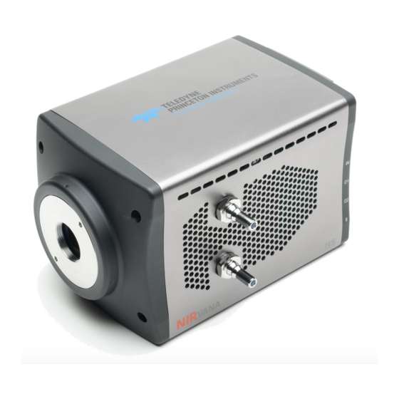
NIRvana HS System Manual Issue 1.0 Refer to Table 2-2, Standard NIRvana HS Camera System Cables, on page 21 for ordering information. Refer to Section 2.8, Accessories, on page 23 for information about accessories. NIRvana HS Camera The NIRvana HS camera, shown in Figure 2-2, is regulated by an internal controller which receives commands from the host computer/software and converts them to... -
Page 17: Window
Chapter 2 NIRvana HS Camera System 2.1.2 Window The NIRvana HS window is composed of AR-coated fused silica. 2.1.3 Cooling Dark current is reduced in NIRvana HS camera systems by utilizing thermoelectric cooling of the sensors. Cooling by this method uses a Peltier cooler in combination with air-circulation (i.e., fan,) and/or circulating coolant. -
Page 18: External Coolant Circulator
2 liters per minute. NIRvana HSRefer to Table A-6, External Coolant Circulator Specifications, on page 81 for additional information. If desired, contact Teledyne Princeton Instruments for additional recommendations. Refer to Contact Information on page 100 for complete information. -
Page 19: Rear-Panel Connectors
Chapter 2 NIRvana HS Camera System 2.1.4 Rear-Panel Connectors Figure 2-3 illustrates the rear-panel connectors on a NIRvana HS camera. Figure 2-3: NIRvana HS Rear-Panel Connectors Refer to Table 2-1 for information about each rear-panel connector. Table 2-1: NIRvana HS Rear-Panel Connectors (Sheet 1 of 2) Label Description POWER... -
Page 20: Power Supply
Specifications, on page 80 for complete specifications. CAUTION! Use of a power supply other than that provided with the NIRvana HS camera will void the camera warranty. For specific power supply requirements, contact Teledyne Princeton Instruments. Refer to Contact Information page 100 for complete information. -
Page 21: Standard Cables
Chapter 2 NIRvana HS Camera System Standard Cables Table 2-2 describes the cables included with a standard NIRvana HS Camera System. Table 2-2: Standard NIRvana HS Camera System Cables Part Cable Description/Purpose Length Number MCX to BNC 6050-0540 Two MCX to BNC adapter cables are provided Varies Adapter with the NIRvana HS system. -
Page 22: Optical Mounts
Figure 2-4: Available Optical Adapters OUNT PECTROSCOPY OUNT If desired, the alternate mount can be ordered from Teledyne Princeton Instruments. Contact Customer Service for assistance. Refer to Contact Information on page 100 for complete information. The Following adapters are available to convert from/to a different mount: •... -
Page 23: Application Software
When unpacking the system, examine the system components for any signs of shipping damage. If there are any, notify Teledyne Princeton Instruments immediately and file a claim with the carrier. Be sure to save the shipping carton for inspection by the carrier. -
Page 24: 2.10 Care And Cleaning Of A Nirvana Hs System
2.11 Repairs Because the NIRvana HS camera system contains no user-serviceable parts, repairs must be performed by Teledyne Princeton Instruments. Should your system need repair, contact Teledyne Princeton Instruments customer support for instructions. For contact information, refer to Contact Information on page 100. -
Page 25: Chapter 3: Install Lightfield
Chapter 3: Install LightField This chapter provides the installation procedure for LightField application software. NOTE: If LightField version 6.11 or newer has already been successfully installed on the host computer, this chapter may be skipped. If a LightField software license was not purchased with the camera system, installing LightField using the software CD included with the NIRvana HS will provide users with full software functionality for 45-days from the date of install. - Page 26 NIRvana HS System Manual Issue 1.0 This page is intentionally blank.
-
Page 27: Chapter 4: System Block Diagrams
Chapter 4: System Block Diagrams This chapter provides block diagrams of typical system configurations. Figure 4-1: Typical Imaging Experiment Layout: Air-cooled Camera 80 – 264 V OWER UPPLY USB 3 C ABLE USB 3 VANA OMPUTER AMPLE Figure 4-2: Typical Spectroscopy Experiment Layout: Air-cooled Camera 80–... -
Page 28: Figure 4-3: Typical Imaging Experiment Layout: Air/Liquid-Cooled Camera
NIRvana HS System Manual Issue 1.0 Figure 4-3: Typical Imaging Experiment Layout: Air/Liquid-cooled Camera OWER UPPLY 80 – 264 V USB 3 C ABLE USB 3 VANA AMPLE OMPUTER OOLANT IRCULATOR 110 – 240 V OOLANT OOLANT OOLANT OSES Figure 4-4: Typical Spectroscopy Experiment Layout: Air/Liquid-cooled Camera 80 –... -
Page 29: Chapter 5: Hardware Configuration
Chapter 5: Hardware Configuration This chapter provides information about the installation and configuration of a NIRvana HS camera system. CAUTION! Overexposure Protection: Cameras that are exposed to room light or other continuous light sources will quickly become saturated. Set the lens to the smallest aperture (i.e., highest f-number,) and cover the lens with a lens cap to prevent overexposure. -
Page 30: Figure 5-1: Adjustable C-Mount Adapter
NIRvana HS System Manual Issue 1.0 Figure 5-1: Adjustable C-Mount Adapter CREW DJUSTABLE OUNT DAPTER OVER PANNER OLES (2) S PANNER RENCH OLES 0.10” [2.5 0.15” [3.8 DIAMETER X 2. Using a spanner wrench (or equivalent,) rotate the ring to the desired height. NOTE: The distance between the two adapter holes is 3.85”... -
Page 31: Mounting The Camera
Chapter 5 Hardware Configuration Mounting the Camera The NIRvana HS is equipped with a 1/4-20 mounting hole on the bottom of the camera (see Appendix B). This allows the camera to be mounted in any orientation... -
Page 32: External Coolant Circulator Use
NIRvana HS System Manual Issue 1.0 External Coolant Circulator Use For liquid-cooled cameras, an external coolant circulator provides a vibration-free method of heat removal. Perform the following procedure to connect an external coolant circulator to a liquid-cooled NIRvana HS camera: NOTE: For specific configuration information, refer to the manufacturer-supplied documentation included with the... -
Page 33: Experiment Shutdown
Chapter 5 Hardware Configuration 4. Verify that the reservoir on the external coolant circulator contains sufficient coolant as specified by it manufacturer. If additional coolant is required, use a 50:50 mixture of water and ethylene glycol based commercial antifreeze to add sufficient coolant. - Page 34 NIRvana HS System Manual Issue 1.0...
-
Page 35: First Light
Chapter 6: First Light Once the NIRvana HS camera hardware has been configured as described in Chapter 5, Hardware Configuration, operation of the camera is straightforward. For most applications simply: • Establish optimum performance using Preview mode; • Set a target temperature for the NIRvana HS system; •... - Page 36 NIRvana HS System Manual Issue 1.0 Whether data are displayed and/or stored depends on the data collection operation that has been selected in the application software: • Preview This mode is typically used when setting up the system during First Light procedures.
-
Page 37: Imaging Applications
Chapter 6 First Light Imaging Applications This section provides step-by-step instructions for acquiring an image in LightField for the first time. The intent of this procedure is to help gain basic familiarity with the operation of the system and to show that it is functioning properly. Once basic familiarity has been established, then operation with other operating configurations, ones with more complex timing modes, can be performed. -
Page 38: Figure 6-3: Typical Experiment Devices Area: Adding Nirvana Hs Camera
NIRvana HS System Manual Issue 1.0 Figure 6-3: Typical Experiment Devices Area: Adding NIRvana HS Camera The Experiment Settings stack on the left now includes expanders. See Figure 6-4. Figure 6-4: Typical Workspace: NIRvana HS Camera Since this is a new experiment, default values for the NIRvana HS configuration parameters will be used. -
Page 39: Data Acquisition
Chapter 6 First Light 6.1.1 Data Acquisition Perform the following procedure to acquire data: Click on the View tab to change to the display area. See Figure 6-5. Figure 6-5: Typical Imaging Application Workspace: View Tab 2. Click Run to start Preview mode. In this mode, images are continuously acquired and displayed. -
Page 40: Shut Down Procedure
NIRvana HS System Manual Issue 1.0 3. Adjust the lens aperture, intensity scaling, and focus for the best image as viewed on the computer monitor. Imaging tips include: • Begin with the lens blocked off and then set the lens to the smallest possible aperture (i.e., the greatest f-stop number.) •... -
Page 41: Spectroscopy Applications
2. Turn on the spectrograph. ® 3. Mount a light source such as a Teledyne Princeton Instruments IntelliCal Hg/Ne-Ar Dual Switchable light source in front of the entrance slit. 4. Connect the Shutter connector on rear of the NIRvana HS to the shutter driver. -
Page 42: Figure 6-7: Typical Devices Tab: Spectroscopy Application
NIRvana HS System Manual Issue 1.0 10. After LightField has launched, icons representing the camera and spectrograph are shown in the Available Devices area. See Figure 6-7. Figure 6-7: Typical Devices Tab: Spectroscopy Application 11. Drag each icon into the Experiment Devices area. See Figure 6-8. -
Page 43: Figure 6-9: Typical Workspace: Nirvana Hs Camera With Spectrograph
Chapter 6 First Light Figure 6-9: Typical Workspace: NIRvana HS Camera with Spectrograph Since this is a new experiment, default values for the NIRvana HS and spectrograph configuration parameters will be used. The Status Bar across the bottom of the workspace includes an icon for Temperature Status. -
Page 44: Rotational Alignment And Focus
NIRvana HS System Manual Issue 1.0 18. If there is little or no difference between the data displayed when the light source is on or off: a. Verify that the light source has power and is turned on. b. Verify that the entrance slit is open a minimum of 10 m. c. -
Page 45: Rotational Alignment
Chapter 6 First Light 6.2.1.1 Rotational Alignment Perform the following procedure to rotationally align the system: Click on the View tab located just above Experiment Devices to change to the display area. See Figure 6-10. Figure 6-10: Typical Spectroscopy Application Workspace: View Tab 2. -
Page 46: Figure 6-11: Experiment Options ► Align Spectrometer Selection
NIRvana HS System Manual Issue 1.0 7. Select Align Spectrometer… from the Experiment Options menu. See Figure 6-11. Figure 6-11: Experiment Options Align Spectrometer Selection ► 8. The Spectrometer Alignment dialog is displayed in which changes to be made to the NIRvana HS system configuration parameters are outlined. -
Page 47: Focus
Focusing is accomplished depending on the spectrograph being used as follows: • Long focal-length spectrographs (e.g., a Teledyne Acton Research SP-2300) The mounting adapter includes a tube that slides inside another tube to move the camera in or out as required to achieve optimum focus. -
Page 48: Acquire Data
NIRvana HS System Manual Issue 1.0 6.2.2 Acquire Data After the system has been successfully aligned and focused, perform the following procedure to acquire data: Stop running in Alignment mode. 2. Make any required changes to the experiment setup and/or software parameters. Changes might include adjusting exposure time, setting up an entrance slit shutter, changing the timing mode to External Sync, or lowering the temperature. -
Page 49: Exposure
Chapter 7: Exposure This chapter discusses factors that affect exposure and the accumulation of charge on the FPA sensor. A Focal Plane Array (FPA) such as the one in NIRvana HS is a matrix of photodiodes bonded to a readout circuit on an IC chip. The photodiodes are sensitive to NIR wavelengths in which they absorb NIR radiation, convert it into electrons, and send a voltage signal in response to form an image. -
Page 50: Noise Sources
CAUTION! If a sudden change is observed in the baseline signal, there may be excessive humidity in the camera vacuum enclosure. Turn off the camera and contact Teledyne Princeton Instruments Customer Support. Refer to Contact Information on page 100 for complete contact information. - Page 51 Chapter 7 Exposure When vibration may affect results, fan operation can be turned off while making sure that the coolant is circulating through the camera to maintain the sensor cooling temperature. If the fan is turned off and there is no coolant circulating through the camera, the built-in thermo-protection switch may shut the camera down to prevent thermal damage.
- Page 52 NIRvana HS System Manual Issue 1.0 This page is intentionally blank.
-
Page 53: Readout
Chapter 8: Readout This chapter discusses topics related to the reading out of data that have been acquired by a NIRvana HS camera. Modes NIRvana HS supports two Readout Modes: • The first and most common mode is Full Frame Readout, also referred to as Integrate Then Read (ITR). -
Page 54: Full Frame Readout
NIRvana HS System Manual Issue 1.0 Readout rate is configured in LightField on the Analog to Digital Conversion expander via the Speed parameter. See Figure 8-2. Figure 8-2: Typical Analog to Digital Conversion Expander Using the full camera resolution of 640 x 512, the readout times of the camera are approximately 31 ms, 8 ms, and 4 ms respectively. -
Page 55: Expose During Readout
Chapter 8 Readout Figure 8-3: Timing Diagram: Full Frame Readout, t > t RAME XPOSE RAME XPOSE RAME XPOSE 8.1.2 Expose During Readout Using Expose During Readout generally yields faster Frame Rates with no gaps in acquired data as well as less lag time. Expose During Readout is particularly useful when Exposure Time and Readout Time are in the same magnitude. -
Page 56: Exposure Time Is Longer Than Or Equal To Readout Time
NIRvana HS System Manual Issue 1.0 8.1.2.1 Exposure Time is Longer Than or Equal to Readout Time Figure 8-4 illustrates the timing diagram for Expose During Readout when Exposure Time is longer than Readout Time. NOTE: Figure 8-5 also applies to applications when Exposure Time equals Readout Time. -
Page 57: Exposure Time Is Shorter Than Readout Time
Chapter 8 Readout 8.1.2.2 Exposure Time is Shorter than Readout Time Figure 8-5 illustrates the timing diagram for Expose During Readout when Exposure Time is shorter than Readout Time. Figure 8-5: Timing Diagram: Frame Transfer Readout, t < t RAME EADOUT RAME EADOUT... -
Page 58: Full Frame Readout Versus Expose During Readout
NIRvana HS System Manual Issue 1.0 8.1.3 Full Frame Readout versus Expose During Readout When deciding on the readout mode to be used, keep in mind that: • Expose During Readout provides the fastest Frame Rate; • Full Frame Readout provides the lowest noise readout. Table 8-1 compares frame rates for these two Readout modes for a variety of Exposure Times and Readout Rates. -
Page 59: Determine The Best Readout Mode For An Application
Chapter 8 Readout 8.1.4 Determine the Best Readout Mode for an Application When deciding on the best readout mode for an application, consider the following: • For the lowest noise possible, use the 3.125 MHz clock and Full Frame readout mode. -
Page 60: Single Region Of Interest Placement Guidelines
NIRvana HS System Manual Issue 1.0 8.2.2 Single Region of Interest Placement Guidelines For imaging applications, when positioning/placing a single Region of Interest the greatest improvement in Readout Time/Frame Rate is achieved when the ROI is positioned such that, referencing a standard (x, y) coordinate system, its corners are placed such that: •... -
Page 61: Figure 8-6: Vertically Stacked Rois With Small Vertical Gap
Chapter 8 Readout Figure 8-6 illustrates two vertically stacked Regions of Interest with a small vertical gap. The measured readout rate is 96.3 fps. Figure 8-6: Vertically Stacked ROIs with Small Vertical Gap = 96.3 fps RAME Figure 8-7 illustrates two vertically stacked Regions of Interest with a large vertical gap. The measured readout rate is 96.3 fps. -
Page 62: Figure 8-8: Horizontally Aligned Rois With Large Horizontal Gap
NIRvana HS System Manual Issue 1.0 Figure 8-8 illustrates two vertically aligned Regions of Interest with a large horizontal. The measured readout rate is 82.6 fps. Figure 8-8: Horizontally Aligned ROIs with Large Horizontal Gap 240 C OLUMN =82.6 fps RAME Figure 8-9 illustrates two vertically aligned Regions of Interest with a small horizontal... -
Page 63: Figure 8-10: Vertically Aligned Mid-Sensor Rois With Large Horizontal Gap
Chapter 8 Readout Figure 8-10 illustrates two vertically aligned Regions of Interest with a large horizontal gap. The regions are vertically mid-sensor. The measured readout rate is 82.6 fps. Figure 8-10: Vertically Aligned Mid-Sensor ROIs with Large Horizontal Gap 240 C OLUMN = 82.6 fps RAME... -
Page 64: Figure 8-12: Vertically Offset Rois With Large Horizontal Gap, No Vertical Gap Or
NIRvana HS System Manual Issue 1.0 Figure 8-12 illustrates two vertically offset Regions of Interest with a large horizontal gap, no overlapping rows, and no vertical gap. The measured readout rate is 41 fps. Figure 8-12: Vertically Offset ROIs with Large Horizontal Gap, No Vertical Gap or Row Overlap 240 C OLUMN... -
Page 65: Number Of Regions Of Interest
Chapter 8 Readout Figure 8-14 illustrates three Regions of Interest with horizontal gaps and multiple overlapping rows. The measured readout rate is 32.3 fps. Figure 8-14: Three ROIs with Horizontal Gaps and Overlapping Rows =32.3 fps RAME 8.2.5 Number of Regions of Interest When it comes to the creation of ROIs, more is not always better, and creating an excessive number of smaller ROIs may yield minimal frame rate increase. -
Page 66: Analog Gain
NIRvana HS System Manual Issue 1.0 Analog Gain Analog Gain is used to change the number of electrons required to generate an Analog-to-Digital Unit (ADU,) also known as a count. The Analog Gain is configured on the Analog to Digital Conversion expander. Analog Gain Control determines how many photons are required to generate an analog-to-digital unit. -
Page 67: Digitization
Chapter 8 Readout Digitization After gain has been applied to the signal, the Analog-to-Digital Converter (ADC) converts the analog information (continuous amplitudes) into digital data (quantified, discrete steps) that can be read, displayed, and stored by the application software. Digitization Resolution is 16 bits. Factors associated with digitization include the digitization rate and baseline signal. -
Page 68: Adc Offset (Baseline Offset)
CAUTION! If a sudden change in the baseline signal is observed, there may be excessive humidity in the detector vacuum enclosure. Turn off the camera and contact Teledyne Princeton Instruments Customer Support for instructions. -
Page 69: Data Correction
Chapter 9: Data Correction This chapter discusses the methods incorporated by NIRvana HS for correcting data. For each individual camera, specific correction data are determined during the manufacturing process. All necessary correction data are stored within the camera's non-volatile flash memory (NVRAM.) During camera start-up, the available correction data are copied from the flash memory onto the correction data memory for real time access. -
Page 70: Flatfield Correction
NIRvana HS System Manual Issue 1.0 Figure 9-1: Typical Online Corrections Expander: Background Subtraction Flatfield Correction Non-uniformity of illumination sources, optical non-uniformity (i.e., vignetting,) and/or the non-uniformity of the InGaAs detector can be compensated for by applying Flatfield Correction. This procedure is performed by first setting up the experiment parameters, waiting until the detector has reached operating temperature to ensure stability, and taking a Flatfield Reference image of the illumination source (without the sample.) -
Page 71: Defect/Blemish Correction
All NIRvana HS cameras have a defect map pre-loaded into camera NVRAM. LightField creates a Blemish Definition file to correct for any inherent defects/blemishes that have been identified on the sensor by Teledyne Princeton Instruments. If additional corrections are required, customers can manually edit this Blemish Definition File. - Page 72 NIRvana HS System Manual Issue 1.0 This page is intentionally blank.
-
Page 73: Chapter 10: Advanced Topics
Chapter 10: Advanced Topics Previous chapters discussed the configuration of hardware and software for basic operation. This chapter discusses the following topics associated with experiment synchronization: • Shutter Control Modes; • Trigger Response Modes; • Output Signal Control. NOTE: Configuration parameters discussed in this section are found on the following expanders: •... -
Page 74: 10.2 Trigger Response Modes
NIRvana HS System Manual Issue 1.0 10.2 Trigger Response Modes NIRvana HS’s Trigger Response modes for Full Frame operation are: • No Response; • Start On Single Trigger; • Readout Per Trigger; • Expose During Trigger Pulse. Timing mode, when combined with the Shutter Mode options, provide the widest variety of modes for precision experiment synchronization. -
Page 75: No Response
Chapter 10 Advanced Topics 10.2.2 No Response In this mode, the camera ignores any external triggers and all settings are obtained from the setup parameters, making the duration of each exposure time constant and the interval times between exposures constant. NOTE: Open Before Trigger mode is not permitted in this triggering mode. -
Page 76: Expose During Trigger Pulse
NIRvana HS System Manual Issue 1.0 10.2.4 Expose During Trigger Pulse When Expose During Trigger Pulse timing is selected, the camera exposure is determined by the TRIGGER IN input on the camera (see Figure 10-1) which allows an external timing generator to control the exposure time for the camera. The transition from the inactive state to the active state of the input at the TRIGGER IN connector starts the exposure, while the transition from the active state to the inactive state ends the exposure. -
Page 77: 10.3 Output Signal Control
Chapter 10 Advanced Topics 10.3 Output Signal Control This section provides information about the use of the OUT1 and OUT 2 connectors on the rear of the NIRvana HS. The signals at these connectors can be used to monitor camera operation or synchronize with external equipment. The TTL-compatible logic level output (i.e., 0 to +3.3 V ) from the OUT 1/OUT 2 connectors on the rear panel can be used to monitor camera status and control... - Page 78 NIRvana HS System Manual Issue 1.0 Additional related signals and configuration settings include: • Exposing This level is at a logic high during the programmed exposure time (i.e., the time configured in the software.) • Effectively Exposing This level is at a logic high during the effective exposure time. This exposure time equals the read out time in Expose During Readout mode when the exposure time is less than the readout time.
-
Page 79: Appendix A: Technical Specifications
All specifications are subject to change. This appendix provides some technical information and specifications for NIRvana HS cameras and optional accessories. Additional information may be found on data sheets available on the Teledyne Princeton Instruments website (www.princetoninstruments.com). System Dimensions and Weight... -
Page 80: Thermal Characteristics
AC plug from the wall receptacle. CAUTION! Use of a power supply other than that provided with the NIRvana HS camera will void the camera warranty. For specific power supply requirements, contact Teledyne Princeton Instruments. Refer to Contact Information page 100 for complete information. -
Page 81: Environmental Specifications
Appendix A Technical Specifications Refer to Table A-4 for power specifications for the external NIRvana HS power supplies. Table A-4: Power Specifications Parameter Specification Input Voltage 80 - 264 V Input Frequency 43 - 63 Hz Output 12 V at 11.5 A Environmental Specifications Refer to Table A-5... -
Page 82: Minimum Host Computer Specifications
NIRvana HS System Manual Issue 1.0 Minimum Host Computer Specifications NOTE: Computers and operating systems experience frequent updates. Therefore, the following sections are intended to provide minimum system requirements for operating a NIRvana HS camera. A faster computer with a minimum of 16 GB memory (RAM) will greatly enhance the software performance during live mode operations. -
Page 83: Appendix B: Outline Drawings
Appendix B: Outline Drawings NOTE: All dimensions are listed in inches [mm]. Figure B-1: Outline Drawing: NIRvana HS with C-Mount... -
Page 84: Figure B-2: Outline Drawing: Nirvana Hs With Spectroscopy-Mount
NIRvana HS System Manual Issue 1.0 Figure B-2: Outline Drawing: NIRvana HS with Spectroscopy-Mount... -
Page 85: Appendix C: Optical Mount Removal And Replacement
Appendix C: Optical Mount Removal and Replacement This appendix provides the procedures to remove and replace the optical mounts for a NIRvana HS. NOTE: The remove and replace procedures are identical for the C- and Spectroscopy optical mounts. The following tools are required: •... -
Page 86: Figure C-1: Nirvana Hs With Optical Mount Facing Up And Camera Bottom
NIRvana HS System Manual Issue 1.0 Figure C-1: NIRvana HS with Optical Mount Facing Up and Camera Bottom Identified AISED 1/4-20 WITH TAPPED HOLE 2. Use the 7/64” Hex Driver to loosen the four (4) screws securing the optical mount to the camera chassis. -
Page 87: Optical Mount Reference Drawings
Appendix C Optical Mount Removal and Replacement 3. Carefully lift the optical mount up and away from the camera chassis. Retain the fours (4) sets of mounting hardware as they will be required for installing the alternate optical mount. Each set of hardware comprises: •... -
Page 88: Figure C-4: Optical Spectroscopy-Mount Reference Exploded View
NIRvana HS System Manual Issue 1.0 Figure C-4 illustrates an exploded view of the Optical Spectroscopy-Mount. Figure C-4: Optical Spectroscopy-Mount Reference Exploded View 6-32 CREW 2826-0215 PLIT ASHER 2828-0029 ASHER 2828-0072... -
Page 89: Appendix D: Calibration Charts
Appendix D: Calibration Charts This appendix provides the following calibration charts for use with the NIRvana HS camera in spectroscopic applications: • HG Calibration Spectrum for NIRvana HS; • Ne-Ar Calibration Spectrum for NIRvana HS. -
Page 90: Figure D-1: Hg Spectrum: Nirvana Hs 1.7/Sp-2500
NIRvana HS System Manual Issue 1.0 Figure D-1: Hg Spectrum: NIRvana HS 1.7/SP-2500... -
Page 91: Figure D-2: Ne/Ar Spectrum: Nirvana Hs 1.7/Sp-2500
Appendix D Calibration Charts Figure D-2: Ne/Ar Spectrum: NIRvana HS 1.7/SP-2500... - Page 92 NIRvana HS System Manual Issue 1.0 This page is intentionally blank.
-
Page 93: Appendix E: Troubleshooting
If you are sure the problem is in the camera system hardware, begin with the following simple checks: • Turn off all AC power. • Verify that all cables are securely fastened. • Turn the system on. If the system still does not respond, contact Teledyne Princeton Instruments Customer Support. -
Page 94: External Coolant Circulator: Low Coolant (Air In The Hoses)
Turn the circulator back on. — If there are no problems, proceed to step 8. — If the problem persists, turn off the system, and contact Teledyne Princeton Instruments Customer Support. Refer to Contact Information on page 100 for complete contact information. -
Page 95: Cooling Troubleshooting
Contact the factory to make arrangements for returning the camera to the support facility. Teledyne Princeton Instruments guarantees a permanent vacuum for the life of a NIRvana HS camera. -
Page 96: Device Is Not Found
NIRvana HS System Manual Device Is Not Found When LightField is launched, it looks for devices (e.g., cameras, spectrographs, and filters,) that are powered on and connected via a communications interface with the host computer. If it cannot find a device that had been used in the last experiment, it will continue to look for it. -
Page 97: Warranty And Service
(1) year after shipment. During this period, Teledyne Princeton Instruments will repair the product or, at its sole option, repair or replace any defective part without charge to you. You must deliver the entire product to the Teledyne Princeton Instruments factory or, at our option, to a factory-authorized service center. -
Page 98: Sealed Chamber Integrity Limited 12 Month Warranty
(1) year from shipment. Teledyne Princeton Instruments does not warrant that the function of the software will meet your requirements or that operation will be uninterrupted or error free. -
Page 99: Owner's Manual And Troubleshooting
3. All warranty service must be made by the Teledyne Princeton Instruments factory or, at our option, an authorized service center. 4. Before products or parts can be returned for service you must contact the Teledyne Princeton Instruments factory and receive a return authorization number (RMA.) Products or parts returned for service without a return authorization evidenced by an RMA will be sent back freight collect. -
Page 100: Contact Information
In no event shall Teledyne Princeton Instruments’ liability exceed the cost of the repair or replacement of the defective product or part. - Page 101 This page is intentionally blank.
- Page 102 info@princetoninstruments.com USA +1 877-474-2286 | France +33 (1) 60 86 03 65 | Germany +49 (0) 89 660 7793 | UK & Ireland +44 (0) 1628 472 346 Singapore +65 6408 6240 | China +86 10 659 16460 | Japan +81 (3) 5639 2741...
-
Page 103: Row Overlap64
Figure 2-1: NIRvana HS Camera System: Standard Items ..... 15 Figure 2-2: Typical NIRvana HS Camera........16 Figure 2-3: NIRvana HS Rear-Panel Connectors . -
Page 104: Identified 86
Figure C-1: NIRvana HS with Optical Mount Facing Up and Camera Bottom Identified 86 Figure C-2: Retaining Hardware Securing Optical Mount to Camera Chassis . . . 86 Figure C-3: Optical C-Mount Reference Exploded View ..... .87 Figure C-4: Optical Spectroscopy-Mount Reference Exploded View . -
Page 105: Table 8-1: Full Frame Readout Vs. Expose During Readout Frame Rate Comparison
Table 1-1: Related Documentation ........11 Table 2-1: NIRvana HS Rear-Panel Connectors . - Page 107 All rights reserved. No part of this publication may be reproduced by any means without the written permission of Teledyne Princeton Instruments. Printed in the United States of America. NIRvana, IntelliCal, PVCam, and LightField are registered trademarks of Teledyne Digital Imaging US, Inc..
Need help?
Do you have a question about the Princeton Instruments NIRvana HS and is the answer not in the manual?
Questions and answers