
Related Manuals for Teledyne Princeton Instruments NIRvana


Summary of Contents for Teledyne Princeton Instruments NIRvana
- Page 1 PhotonMAX System Manual 4411-0107 Issue 2 June 5, 2019 www.princetoninstruments.com...
- Page 2 Trenton, NJ 08619 TEL: 800-874-9789 / 609-587-9797 FAX: 609-587-1970 All rights reserved. No part of this publication may be reproduced by any means without the written permission of Teledyne Princeton Instruments. Printed in the United States of America. LabVIEW is a registered trademark of National Instruments, Inc.
-
Page 3: Table Of Contents
Table of Contents Chapter 1: About this Manual..........7 Intended Audience . - Page 4 PhotonMAX System Manual Issue 2 Make Camera-Circulator Connections ........31 Software Installation .
- Page 5 Issue 2 Table of Contents Chapter 7: Troubleshooting ..........91 Baseline Signal Suddenly Changes .
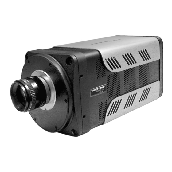
- Page 6 PhotonMAX System Manual Issue 2 List of Figures Figure 2-1: Typical PhotonMAX System Components ......11 Figure 2-2: Typical PhotonMAX: 512B Camera .
- Page 7 Issue 2 List of Figures ► Figure 5-29: Typical Hardware Setup Dialog Cleans Tab: Clean Mode ..71 Figure 5-30: Timing Diagram: Non-Overlap Mode......71 ►...
- Page 8 PhotonMAX System Manual Issue 2 List of Tables Revision History ..........2 Table 1-1: Related Documentation .
-
Page 9: About This Manual
PVCam Software Users Manual Teledyne Princeton Instruments maintains updated documentation and user manuals on their FTP site. Visit the Teledyne Princeton Instruments FTP Site to verify that the most recent user manual is available and being referenced: ftp://ftp.piacton.com/Public/Manuals/Princeton Instruments ftp://ftp.piacton.com/Public/Manuals/Acton... -
Page 10: Document Organization
This appendix provides CCD, system, and other technical specifications for the PhotonMAX camera system. • Appendix B, Outline Drawings This appendix provides outline drawings for the PhotonMAX camera system. • Warranty and Service This chapter provides the Teledyne Princeton Instruments warranty and customer support contact information. -
Page 11: Safety Related Symbols Used In This Manual
WARNINGS! If the PhotonMAX camera system is used in a manner not specified by Teledyne Princeton Instruments, the protection provided by the equipment may be impaired. 2. If the equipment or the wall outlet is damaged, the protective grounding could be disconnected. -
Page 12: Precautions
4. Do not block air vents on the camera. Preventing the free flow of air overheats the camera and may damage it. 5. If the PhotonMAX camera system is used in a manner not specified by Teledyne Princeton Instruments, the protection provided by the equipment may be impaired. 1.6.1... -
Page 13: Photonmax Camera System
Chapter 2: PhotonMAX Camera System This chapter provides an introduction to, and overview information about, Teledyne Princeton Instruments’s PhotonMAX camera system. Figure 2-1 shows those items that are typically included as part of a standard PhotonMAX Camera system. Figure 2-1:... -
Page 14: Photonmax Camera
PhotonMAX System Manual Issue 2 PhotonMAX Camera The new PhotonMAX cameras feature on-chip multiplication gain, a technology that enables the multiplication of photon generated charge right on the CCD. This approach offers an effective alternative to traditional ICCD cameras for many non-gated, low-light applications. -
Page 15: Integrated Controller
Large full wells, square pixels, and 100% fill factors provide high dynamic range and excellent spatial resolution. Unichrome (exclusive Teledyne Princeton Instruments technology) and other UV-enhancement coatings can be used... -
Page 16: Cooling
PhotonMAX System Manual Issue 2 2.1.4 Cooling Dark current is reduced in PhotonMAX camera systems through thermoelectric cooling of the CCD arrays. Cooling by this method uses a four-stage Peltier cooler in combination with air-circulation or circulating coolant. To prevent condensation and contamination from occurring, cameras cooled this way are evacuated. -
Page 17: Coolcube Coolant Circulator
Chapter 2 PhotonMAX Camera System Refer to Table 2-1 for information about each of these connectors and ports. Table 2-1: PhotonMAX Camera Connectors and Ports Connector/Port Description Data 20-pin, high-density connector for data transfer. DB-26 high-density connector for input/output control signals. Power 5-pin LEMO connector for camera power. -
Page 18: Cables
PhotonMAX System Manual Issue 2 Cables Table 2-2 describes the cables included with a standard PhotonMAX Camera System. Table 2-2: Standard PhotonMAX Camera System Cables Part Cable Description/Purpose Number Data Cable 6050-0545 The Data cable has 20-pin, high-density (MDR-20) connectors for interconnecting the camera and the host computer. -
Page 19: Certificate Of Performance
Certificate of Performance Each PhotonMAX camera is shipped with a Certificate of Performance which states that the camera system has been assembled and tested according to approved Teledyne Princeton Instruments procedures. It documents the camera’s performance data as measured during the testing of the PhotonMAX and lists the following camera- and customer-specific information: •... -
Page 20: Fiber Optic Interface
Scientific Imaging ToolKit™ (SITK™) ® A collection of LabVIEW VIs for scientific detectors and spectrographs. This third party software can be purchased from Teledyne Princeton Instruments. NOTE: PhotonMAX cameras may also be operated by several other third-party software packages. Please check with the providers of the packages for compatibility and support information. -
Page 21: Photonmax Camera And System Maintenance
2.7.3 Repairs Because the PhotonMAX camera system contains no user-serviceable parts, repairs must be performed by Teledyne Princeton Instruments. Should the system need repair, contact Teledyne Princeton Instruments customer support for instructions. Refer to Contact Information on page 120 for complete information. - Page 22 PhotonMAX System Manual Issue 2 This page is intentionally blank.
-
Page 23: Installation Overview
Chapter 3: Installation Overview Table 3-1 lists the sequence of actions required to install a PhotonMAX system and prepare to gather data. Refer to the indicated references for additional information. Refer to Section 3.1, System Block Diagrams, on page 23 for high-level block diagrams of typical system configurations. - Page 24 PhotonMAX System Manual Issue 2 Table 3-1: PhotonMAX Installation Actions (Sheet 2 of 2) Action Refer to… 13. When the system reaches temperature lock, wait an additional Section 5.1, First Light: 20 minutes and then begin acquiring data in focus mode. Imaging Applications page 40.
-
Page 25: System Block Diagrams
Chapter 3 Installation Overview System Block Diagrams This section provides typical system-level block diagrams. Figure 3-1: Block Diagram: Typical Imaging Experiment with Air-Cooled PhotonMAX Figure 3-2: Block Diagram: Typical Spectroscopy Experiment with Air-Cooled PhotonMAX... -
Page 26: Figure 3-3: Block Diagram: Typical Imaging Experiment With Liquid-Cooled
PhotonMAX System Manual Issue 2 Figure 3-3: Block Diagram: Typical Imaging Experiment with Liquid-Cooled PhotonMAX Figure 3-4: Block Diagram: Typical Spectroscopy Experiment with Liquid-Cooled PhotonMAX... -
Page 27: System Setup
Keep all the original packing materials so you can safely ship the PhotonMAX system to another location or return it for service if necessary. If you have any difficulty with any step of the instructions, contact Teledyne Princeton Instruments Customer Support. Refer to Contact Information on page 120 for complete information. -
Page 28: Unpack The System
When unpacking the system, examine the system components for any signs of shipping damage. If there are any, notify Teledyne Princeton Instruments immediately and file a claim with the carrier. Be sure to save the shipping carton for inspection by the carrier. -
Page 29: Ventilation
Chapter 4 System Setup 4.2.2 Ventilation • Camera Allow a minimum of 2 inches [50 mm] clearance around the vented covers. The air needs to be less than 25°C (above this temperature the CCD temperature can begin to degrade). When the camera is inside an enclosure, the enclosure needs to have unrestricted flow to an open environment. -
Page 30: Host Computer
PhotonMAX System Manual Issue 2 4.2.4 Host Computer This section provides minimum Host Computer specifications. NOTES: Computers and operating systems undergo frequent revision. The following information is intended to provide an approximate indication of the computer requirements. Contact the factory to confirm specific requirements. -
Page 31: Attach A Lens To A C-Mount Adapter
(highest f-number) and cover the lens with a lens cap to prevent overexposure. PhotonMAX cameras for imaging applications incorporate an integral C-mount adapter. Other mounts may be available. Contact Teledyne Princeton Instruments Customer Service for specific information relating to your application. Refer to Contact Information on page 120 for complete information. -
Page 32: Adjust The C-Mount Adapter
PhotonMAX System Manual Issue 2 Adjust the C-Mount Adapter The PhotonMAX features an adjustable C-mount adapter that allows you to change the focal depth. See Figure 4-1. Figure 4-1: Adjustable C-Mount Adapter Use the hex wrench supplied with the system (or a 0.050” hex wrench,) to adjust the adapter as follows: a. -
Page 33: Make Camera-Circulator Connections
Software Installation This section provides the necessary procedure for installing the software: NOTES: If using multiple cameras from Teledyne Digital Imaging US, Inc. on the same host computer, it may be necessary to edit the PVCAM.INI file. Refer to Section 7.10, Edit the PVCAM.INI... -
Page 34: Figure 4-2: Typical Winview/32 Installation Dialog: Select Components
PhotonMAX System Manual Issue 2 Figure 4-2: Typical WinView/32 Installation Dialog: Select Components Select the Custom button if you would like to choose among the available program files or do not want to install the drivers. 2. Verify the camera is connected to the host computer and that the camera power supply is turned on. -
Page 35: Configure Default Camera System Parameters In Winx/32
2. Launch the WinX/32 application. The Camera Detection wizard will automatically run if this is the first time you have installed a Teledyne Princeton Instruments WinX/32 application and a supported camera. Otherwise, when installing a new camera type, click on the Launch Camera Detection Wizard…... -
Page 36: Figure 4-4: Typical Hardware Setup Dialog: Controller/Camera Tab
PhotonMAX System Manual Issue 2 4. Follow instructions on the dialog boxes to perform the initial hardware setup. This wizard enters default parameters on the Hardware Setup dialog box tab pages and gives you an opportunity to acquire a single test image to confirm the system is working. -
Page 37: Winx/32 Version 2.5.19.5 And Older
Chapter 4 System Setup • Configure the following parameters on the Cleans tab: — Clean Mode: Select Clear Pre-Sequence. Figure 4-5. Figure 4-5: Typical Hardware Setup Dialog: Cleans Tab 4.7.2 WinX/32 Version 2.5.19.5 and Older Perform the following procedure to configure default system parameters in WinX/32 Version 2.5.19.5 and older: Verify the PhotonMAX is connected to the host computer and that it is turned on. -
Page 38: Figure 4-6: Typical Rsconfig Dialog
PhotonMAX System Manual Issue 2 Figure 4-6: Typical RSConfig Dialog NOTE: If the first camera listed is not the PM Style (PCI) PhotonMAX camera, refer to Section 7.10, Edit the PVCAM.INI File, on page 101 for complete information about editing the PVCAM.INI file. -
Page 39: System Operation
Chapter 4 System Setup System Operation Proceed to the following sections for step-by-step procedures describing basic system operation: • Section 5.1, First Light: Imaging Applications, on page 40; • Section 5.2, First Light: Spectroscopy Applications, on page 46. - Page 40 PhotonMAX System Manual Issue 2 This page is intentionally blank.
-
Page 41: Operation
Chapter 5: Operation Once the PhotonMAX camera has been installed as explained in the preceding chapters, operation of the camera is straightforward. In most applications you simply establish optimum performance using the Focus mode in WinView/32 or WinSpec/32, set the target camera temperature, wait until the temperature has stabilized, and then do actual data acquisition in the Acquire mode. -
Page 42: First Light: Imaging Applications
PhotonMAX System Manual Issue 2 Whether or not the data are displayed and/or stored depends on the data collection operation (i.e., Focus or Acquire,) that has been selected in the application software. In WinView/32 and WinSpec/32, these operations use the Experiment Setup parameters to establish the exposure time (i.e., the period when signal of interest is allowed to accumulate on the CCD.) As might be inferred from the names, Focus is more likely to be used in setting up the system and Acquire is then used for the collection and storage... - Page 43 Chapter 5 Operation Perform the following procedure to configure WinX/32 to acquire an image for the first time: NOTE: The following procedure is based on WinView/32: you will need to modify it if you are using a different application. Basic familiarity with the WinView/32 software is assumed. If this is not the case, you may want to review the software manual or have it available while performing this procedure.
-
Page 44: Figure 5-2: Typical Hardware Setup Dialog: Controller/Camera Tab
PhotonMAX System Manual Issue 2 Figure 5-2: Typical Hardware Setup Dialog: Controller/Camera Tab ► • Cleans tab (Setup Hardware) — Clean Mode Select Clear Pre-Sequence. Figure 5-3. Figure 5-3: Typical Hardware Setup Dialog: Cleans Tab... -
Page 45: Figure 5-4: Typical Photonmax Detector Temperature Dialog
Chapter 5 Operation ► • Detector Temperature (Setup Detector Temperature…) The default temperature setting is read from the camera. When the array temperature reaches the set temperature, the Detector Temperature dialog will report that the temperature is LOCKED. See Figure 5-4. -
Page 46: Figure 5-5: Typical Experiment Setup Timing Tab
PhotonMAX System Manual Issue 2 ► ► • Experiment Setup Timing tab page (Acquisition Experiment Setup…) — Timing Mode Free Run — Shutter Control Normal — Safe Mode vs. Fast Mode Fast Mode Figure 5-5. ► Figure 5-5: Typical Experiment Setup Timing Tab 7. - Page 47 Chapter 5 Operation 8. Adjust the lens aperture, intensity scaling, and focus for the best image as viewed on the computer monitor. Some imaging tips include: • Begin with the lens blocked off and then set the lens at the smallest possible aperture (i.e., largest f-stop number).
-
Page 48: First Light: Spectroscopy Applications
An underlying assumption for this procedure is that the camera is to be operated with a spectrograph (e.g., a Teledyne Acton Research SpectraPro 2356,) on which it has been properly installed. A suitable light source, such as a Mercury pen-ray lamp, should be mounted in front of the entrance slit of the spectrograph. -
Page 49: Figure 5-6: Typical Hardware Setup Dialog: Controller/Camera Tab
Chapter 5 Operation 6. Configure software parameters as follows: ► • Controller/Camera tab (Setup Hardware) These parameters should be set automatically to the proper values for your system. — Use PVCAM Verify that this box is checked. NOTE: This check box is not present on software versions 2.5.19.6 and higher. -
Page 50: Figure 5-7: Typical Hardware Setup Dialog: Cleans Tab
PhotonMAX System Manual Issue 2 ► • Cleans tab (Setup Hardware) — Clean Mode Select Clear Pre-Sequence. Figure 5-7. Figure 5-7: Typical Hardware Setup Dialog: Cleans Tab ► • Detector Temperature (Setup Detector Temperature…) The default temperature setting is read from the camera. When the array temperature reaches the set temperature, the Detector Temperature dialog will report that the temperature is LOCKED. -
Page 51: Figure 5-9: Typical Experiment Setup Timing Tab
Chapter 5 Operation Note that some overshoot may occur. This could cause temperature lock to be briefly lost and then quickly re-established. If you are reading the actual temperature reported by the application software, there may be a small difference between the set and reported temperature when lock is established. This is normal and does not indicate a system malfunction. -
Page 52: Focusing
The following procedure, which describes the focusing operation with a Teledyne Acton Research SP-2356 spectrograph, can be easily adapted to other spectrographs. -
Page 53: Exposure And Signal
Chapter 5 Operation 6. Next adjust the rotation. You can do this by rotating the camera while watching a live display of the line. The line will go from broad to narrow and back to broad. Leave the camera rotation set for the narrowest achievable line. -
Page 54: Avalanche Gain (Multiplication Gain)
PhotonMAX System Manual Issue 2 Exposure Time is the time between commands sent by the application software to start and stop signal accumulation on the CCD. In combination with triggers, these commands control when continuous cleaning of the CCD stops and when the accumulated signal will be read out. -
Page 55: Figure 5-12: Dac Setting Versus Charge Multiplication Gain
Chapter 5 Operation As explained previously, the PhotonMAX uses a unique CCD capable of multiplying the charge (i.e., electrons,) generated in the pixels. When the multiplication is sufficiently high, it is possible to see extremely low-light events. The amount of multiplication is controlled by the voltage applied to multiplication register clocks. -
Page 56: Ccd Temperature
PhotonMAX System Manual Issue 2 5.4.3 CCD Temperature As stated previously, lowering the temperature of the CCD will generally enhance the quality of the acquired signal. In EMCCD cameras, lower temperatures result in lower dark current and higher Avalanche Gain (Multiplication Gain.) When WinView/32 or ►... -
Page 57: Dark Charge
CAUTION! If you observe a sudden change in the baseline signal, there may be excessive humidity in the camera vacuum enclosure. Turn off the camera and contact Teledyne Princeton Instruments Customer Support. Refer to Contact Information on page 120 for complete information. -
Page 58: Cleaning
PhotonMAX System Manual Issue 2 5.4.7 Cleaning ► Cleaning is configured on the Setup Hardware dialog, Cleans tab. See Figure 5-14. Figure 5-14: Typical Hardware Setup Dialog: Cleans Tab Cleaning removes charge from the CCD by clocking the charge to the serial register and then directly to ground. - Page 59 Chapter 5 Operation • Clear Post-Sequence Cleans continuously after the data acquisition sequence ends. The camera continues cleaning until: — A new exposure has been set up or started; — The abort command has been sent; — The speed entry number has been changed; —...
-
Page 60: Readout
PhotonMAX System Manual Issue 2 Readout The PhotonMAX:512B and 1024B models use frame transfer CCDs with 512 x 512 and 1024 x 1024 active pixels, respectively. These frame transfer CCDs also have an equivalent number of frame transfer, or masked, pixels as illustrated in Figure 5-15. -
Page 61: Dual-Readout Port Operation
Chapter 5 Operation 5.5.1 Dual-Readout Port Operation The PhotonMAX: 512B and 1024B models are configured with software-selectable dual-readout amplifiers, also referred to as ports, previously illustrated in Figure 5-15 page 58. The two amplifiers are: • Port #1: Multiplication Gain amplifier; •... -
Page 62: Controller Gain
PhotonMAX System Manual Issue 2 • Multiplication Gain When this port is selected, the gain value can be entered on the Experiment ► Setup Main tab. A setting of 0 (zero) results in unity gain and the subsequent DAC settings are exponentially related to the multiplication gain. Since the multiplication gain can be used to overcome the read noise of the fast amplifier, this mode is most useful in applications requiring low-light sensitivity at high frame rates (e.g., Single molecule fluorescence, ion imaging, etc.) -
Page 63: Figure 5-17: Typical Experiment Setup Adc Tab: Configure Controller Gain
Chapter 5 Operation ► Figure 5-17: Typical Experiment Setup ADC Tab: Configure Controller Gain Available selections are: • 1 (Low); Users who measure high-level signals may wish to select Low to allow digitization of larger signals. • 2 (Medium); Medium is suitable for experiments within the mid-level intensity range. •... -
Page 64: Readout Rate
PhotonMAX System Manual Issue 2 5.5.3 Readout Rate PhotonMAX supports two readout rates available on each of the two ports and is ► ► configured on the Acquisition Experiment Setup… ADC tab. See Figure 5-18. ► Figure 5-18: Typical Experiment Setup ADC Tab: Configure Readout Rate A slower readout rate can be used when better noise performance is needed at the expense of frame rate. -
Page 65: Array Orientation
Chapter 5 Operation 5.5.4.1 Array Orientation For square format CCDs (e.g., 512 x 512 or 1024 x 1024,) you may orient the CCD to achieve binning along either direction of the CCD. • Binning along columns (i.e., parallel mode,) provides maximum scan rate and lowest noise. -
Page 66: Overlap Mode
Perform the following procedure to program WinView/32 and WinSpec/32 for Overlap Mode: NOTE: When using non-Teledyne Princeton Instruments data acquisition software different nomenclature may be incorporated. If this is the case, refer to the user manual included with the software for complete information. -
Page 67: Figure 5-21: Typical Experiment Setup
Chapter 5 Operation ► 2. On the Experiment Setup Timing tab, configure Slow Mode vs. Fast Mode for Fast Mode. See Figure 5-21. ► Figure 5-21: Typical Experiment Setup Timing Tab: Slow vs. Fast Mode ► 3. On the Hardware Setup Controller/Camera tab, configure Readout Mode for Frame Transfer. -
Page 68: Figure 5-23: Typical Hardware Setup Dialog Cleans Tab: Clean Mode
PhotonMAX System Manual Issue 2 ► 4. On the Hardware Setup Cleans tab, configure: • Cleaning Mode to Clear Pre-Sequence; • Number of Cleans: 1 or more. Figure 5-23. ► Figure 5-23: Typical Hardware Setup Dialog Cleans Tab: Clean Mode NOTE: The minimum effective exposure time in this mode is the readout time. -
Page 69: Readout Time
Chapter 5 Operation 5.6.1.1 Example 1: Overlap Mode when Exposure Time < Readout Time Consider an application with the following specifications: • Full Frame readout is 34.8 ms; • Exposure time is 10 ms; • 3 frames are acquired in overlap mode. The first frame is exposed precisely for the length of time entered into the software (i.e., 10 ms,) and all subsequent frames are exposed for the readout time. -
Page 70: Readout Time
PhotonMAX System Manual Issue 2 5.6.1.2 Example 2: Overlap Mode when Exposure Time > Readout Time If the Exposure Time has been configure to be 50 ms with the Readout Time remaining at 34.8 ms, the time required to acquire 3 frames is 184.8 ms calculated as follows: (3 x 50 ms) + 34.8 ms for an equivalent, approximate Frame Rate of 16.3 fps calculated as follows: 3 frames ÷... -
Page 71: Non-Overlap Mode
Perform the following procedure to program WinView/32 and WinSpec/32 for Non-Overlap Mode: NOTE: When using non-Teledyne Princeton Instruments data acquisition software different nomenclature may be incorporated. If this is the case, refer to the user manual included with the software for complete information. -
Page 72: Figure 5-27: Typical Experiment Setup Timing Tab: Slow Vs. Fast Mode
PhotonMAX System Manual Issue 2 ► On the Experiment Setup Timing tab, configure Slow Mode vs. Fast Mode for Fast Mode. See Figure 5-27. ► Figure 5-27: Typical Experiment Setup Timing Tab: Slow vs. Fast Mode ► 2. On the Hardware Setup Controller/Camera tab, configure Readout Mode for Frame Transfer. -
Page 73: Non-Overlap Mode Example
Chapter 5 Operation ► 3. On the Hardware Setup Cleans tab, configure: • Cleaning Mode to Clear Pre-Sequence; • Number of Cleans: 1 or more. Figure 5-29. ► Figure 5-29: Typical Hardware Setup Dialog Cleans Tab: Clean Mode 5.6.2.1 Non-Overlap Mode Example Figure 5-30 illustrates the timing diagram for Non-Overlap Mode. - Page 74 PhotonMAX System Manual Issue 2 The time required to acquire 3 frames is 134.4 ms which is calculated as follows: (3 x 10 ms) + (3 x 34.8 ms) for an equivalent, approximate frame rate of 22.3 fps which is calculated as follows: 3 frames ÷...
-
Page 75: Advanced Topics
Chapter 6: Advanced Topics Prior chapters have discussed configuring hardware and software for basic operation. This chapter discusses topics associated with experiment synchronization which is ► configured on the Experiment Setup Timing tab within WinView/32 and WinSpec/32. With the exception of Edge Trigger, the topics are addressed in order of their appearance on the Timing tab as illustrated in Figure 6-1. -
Page 76: External Shutter Operation
PhotonMAX System Manual Issue 2 • Section 6.3, Fast and Safe Modes, on page 78; This section discusses the Fast and the Safe modes. Fast Mode is used for real-time data acquisition, while Safe Mode is used when coordinating acquisition with external devices, or when the host computer’s processor speed is not fast enough to keep pace with the acquisition rate. -
Page 77: Timing Modes
Chapter 6 Advanced Topics The shutter signal options supported in WinView/32 and WinSpec/32 include • Normal; • Disable Opened; • Disable Closed. Disable simply means that the shutter will not operate during the experiment. Disable closed is useful for making dark charge measurements, or when no shutter is present in the camera. -
Page 78: Free Run
PhotonMAX System Manual Issue 2 6.2.1 Free Run In Free Run mode, there is no external triggering and all settings are read from the setup parameters, making the duration of each exposure time constant and the interval times between exposures constant. See Figure 6-3. -
Page 79: Bulb Trigger
Chapter 6 Advanced Topics 6.2.3 Bulb Trigger In Bulb Trigger mode, Exposure Time for each frame is determined by the trigger pulse width. Exposure Time programmed into the software is ignored in this mode. Figure 6-6. Figure 6-6: Timing Diagram: Bulb Trigger, Non-Overlap Mode If a trigger arrives during the readout of the previous frame, it is ignored. -
Page 80: Fast And Safe Modes
PhotonMAX System Manual Issue 2 Figure 6-8 illustrates the timing diagram for a 3 frame sequence acquired using a Single Trigger in Non-Overlap Mode. Figure 6-8: Timing Diagram: Single Trigger, Non-Overlap Mode Fast and Safe Modes The PhotonMAX has been designed to allow the greatest possible flexibility when synchronizing data collection with an experiment. -
Page 81: Figure 6-9: Flowchart: Safe Mode Versus Fast Mode
Chapter 6 Advanced Topics Figure 6-9: Flowchart: Safe Mode versus Fast Mode... -
Page 82: Fast Mode
PhotonMAX System Manual Issue 2 6.3.1 Fast Mode In Fast Mode, the PhotonMAX runs according to the programmed timing of the experiment with no interruptions from the host computer. Fast operation is primarily for collecting real-time sequences of experimental data where timing is critical and events cannot be missed. -
Page 83: Ttl Status Signals
Chapter 6 Advanced Topics TTL Status Signals The I/O (Input/Output Status) connector on the rear panel of the PhotonMAX accesses information about trigger function, DAC, and TTL signals. See Figure 6-10. Figure 6-10: Typical PhotonMAX Rear Panel with I/O Cable Input signals must be a minimum of 3.15 V for a high and less than 0.9 V for a low. -
Page 84: Kinetics Mode [Optional]
PhotonMAX System Manual Issue 2 Kinetics Mode [optional] Kinetics refers to a special readout mode in which a portion of the CCD is illuminated while the rest of the active area is used to store a series of frames. At the end of the exposure-shift sequence, the entire CCD is readout to give a series of subframes (i.e., kinetic frames,) separated in time. -
Page 85: Kinetics Readout
Chapter 6 Advanced Topics 6.5.1 Kinetics Readout Kinetics readout allows a burst of subframes to be acquired with microsecond resolution. This is accomplished by shifting each subframe exposure under the mask before reading it out. Since there is no overhead of readout time between each exposure, faster time resolution is achieved. -
Page 86: Figure 6-14: Acquired Image Data Using Masked Images
PhotonMAX System Manual Issue 2 Figure 6-14 illustrates the images acquired using the masking shown in Figure 6-13. Figure 6-14: Acquired Image Data Using Masked Images T = 0 ) = 60 R ) = 12 R INDOW UBFRAME INDOW UBFRAME ARTIAL ERIES OF... -
Page 87: Triggered Operation
Chapter 6 Advanced Topics 6.5.2 Triggered Operation ► Triggered operation is configured on the Experiment Setup Timing tab by configuring the following parameters: • Timing Mode; Select Single Trigger or Multiple Trigger • Fast Mode versus Safe Mode. Select Safe Mode. Figure 6-16. -
Page 88: Figure 6-18: Timing Diagram: Kinetics Mode, Multiple Trigger
PhotonMAX System Manual Issue 2 • Multiple Trigger. In multiple trigger mode, each exposure-shift cycle is triggered independently. This mode is useful when each subframe needs to be synchronized with a pulsed external light source such as a laser. NOTE: It is particularly important to keep ambient light to a minimum while multiple trigger mode is used. -
Page 89: Cleaning The Ccd
Chapter 6 Advanced Topics 6.5.3 Cleaning the CCD Since Kinetics is most often used in asynchronous, single-shot experiments, it is important that the CCD be cleared of accumulating background or dark charge while it is waiting for an external trigger. To achieve this, PhotonMAX automatically cleans the CCD one row at a time prior to the arrival of the first trigger. - Page 90 PhotonMAX System Manual Issue 2 Within WinView/32, configure the following parameters as indicated: ► • Controller/Camera tab (Setup Hardware) These parameters should be set automatically to the proper values for your system. — Use PVCAM Verify that this box is checked. NOTE: This check box is not present on software versions 2.5.19.6 and higher.
-
Page 91: Summary
Chapter 6 Advanced Topics 6.5.5 Summary The kinetics is a powerful feature that allows a burst of subframes to be captured with microsecond time resolution. However, careful attention must be paid to the optical and timing considerations, namely: • The rows furthest from the serial register need to be illuminated. •... - Page 92 PhotonMAX System Manual Issue 2 This page is intentionally blank.
-
Page 93: Chapter 7: Troubleshooting
Chapter 7: Troubleshooting WARNING! Do not attach or remove any cables while the camera system is powered on. Refer to Table 7-1 for issues which have recommended troubleshooting procedures in this chapter. Table 7-1: List of Recommended Troubleshooting Procedures Information Issue begins on…... -
Page 94: Baseline Signal Suddenly Changes
• Verify that all cables are securely fastened. • Turn the system on. If the system still does not respond, contact Teledyne Princeton Instruments Customer Support. Refer to Contact Information on page 120 for complete information. Camera1 (or Similar Name) in Camera Name Field... -
Page 95: Controller Is Not Responding
Chapter 7 Troubleshooting Controller Is Not Responding If this message pops up when you click on OK after selecting the Interface Type during Hardware Setup (under the WinView/32 or WinSpec/32 Setup menu,) the system has not been able to communicate with the camera. Check to see if camera has been turned ON and if the PCI interface card, its driver, and the DATA cable have been installed. -
Page 96: Cooling Troubleshooting
• The circulator pump is not working. If you do not hear the pump running when the circulator is powered on, turn off the circulator and contact Teledyne Princeton Instruments Customer Support. Refer to Contact Information on page 120 for complete information. -
Page 97: Gradual Deterioration Of Cooling Capability
Chapter 7 Troubleshooting • The vacuum has deteriorated and needs to be refreshed. Contact Teledyne Princeton Instruments Customer Support. Refer to Contact Information on page 120 for complete information. • The target array temperature is not appropriate for your particular camera and CCD array. -
Page 98: Data Overrun Due To Hardware Conflict Message
PhotonMAX System Manual Issue 2 Data Overrun Due to Hardware Conflict Message If the error message similar to that shown in Figure 7-2 is displayed when you try to acquire a test image, acquire data, or run in focus mode, check the CCD array size and then check the DMA buffer size. -
Page 99: Demo Is Only Choice On Hardware Wizard: Interface Dialog
3. Launch RSConfig.exe from the Windows Start Programs Teledyne Princeton Instruments menu or from the directory where you installed WinView/32. 4. When the RSConfig dialog is displayed, you can change the camera name to one that is more specific or you can keep the default name, Camera1. See Figure 7-4. -
Page 100: Demo, High Speed Pci, And Pci (Timer) Are Choices On Hardware Wizard
This information in this section applies only to WinView/32 and WinSpec/32 Versions 2.5.19.0 and older. If there is an installed Teledyne Princeton Instruments (RSPI) high speed card in the host computer and you want to operate a PhotonMAX camera: •... -
Page 101: Figure 7-6: Typical Hardware Wizard: Interface Dialog
3. Launch RSConfig.exe from the Windows Start Programs Teledyne Princeton Instruments menu or from the directory where you installed WinView/32. 4. When the RSConfig dialog is displayed, you can change the camera name to one that is more specific or you can keep the default name, Camera2. See Figure 7-7. -
Page 102: Detector Temperature, Acquire, And Focus Are Grayed Out
PhotonMAX camera. They will also be deactivated if you have installed a camera being run PVCAM and a Teledyne Princeton Instruments (RSPI) high speed PCI card was also detected when RSConfig.exe was run. Determine if the PhotonMAX is connected to the host computer and is powered on. -
Page 103: 7.10 Edit The Pvcam.ini File
Chapter 7 Troubleshooting 7.10 Edit the PVCAM.INI File Perform the following procedure to edit the PVCAM.INI file: Using Notepad or similar text editor, open PVCAM.INI which is located in the Windows directory (e.g., C:\WINNT). 2. Examine the contents of the file, and make the changes highlighted in Table 7-2. -
Page 104: Error Creating Controller Messages
PhotonMAX System Manual Issue 2 7.11 Error Creating Controller Messages An Error Creating Controller message may be displayed if you are using a PVCAM-supported camera and: • You have not run the RSConfig.exe program; Refer to Section 7.7, Demo is only Choice on Hardware Wizard: Interface Dialog, on page 97 for additional information. -
Page 105: 7.12 Program Error Message
Chapter 7 Troubleshooting 7.12 Program Error Message The Program Error dialog, illustrated in Figure 7-12, may be displayed when you try to acquire a test image, acquire data, or run in focus mode and the DMA buffer size is too small. -
Page 106: 7.13 Serial Violations Have Occurred. Check Interface Cable
PhotonMAX System Manual Issue 2 7.13 Serial Violations Have Occurred. Check Interface Cable. The error message shown in Figure 7-13 will appear if you try to acquire an image or focus the camera and either (or both) of the following conditions exists: •... -
Page 107: Appendix A: Technical Specifications
Digitization (Readout) Rates 10 MHz, 5 MHz, 1 MHz NOTE: The arrays listed are those that were available at the time that the manual was written. Contact Teledyne Princeton Instruments for an updated list of arrays supported by the PhotonMAX. Mounts C-mount: Standard threaded video mount. -
Page 108: Camera
PhotonMAX System Manual Issue 2 Camera Cooling: Thermoelectric; air or circulating coolant CCD Operating Temperature: Refer to Table A-2 for specific thermal information. Table A-2: Default Operating Temperature CCD Size Default 512 x 512 -70°C 1024 x 1024 -55°C Temperature Stability: ±0.05°C;... -
Page 109: Figure A-1: Photonmax Rear Panel Connectors
Appendix A Technical Specifications Connectors: Figure A-1 illustrates the rear panel connectors on a PhotonMAX. Figure A-1: PhotonMAX Rear Panel Connectors • POWER Connector Figure A-2 illustrates the PhotonMAX POWER connector diagram. Figure A-2: PhotonMAX POWER Connector Diagram Table A-3 provides pin assignment information for the PhotonMAX POWER connector. -
Page 110: Figure A-3: Photonmax I/O Connector Diagram
PhotonMAX System Manual Issue 2 • DATA Connector 20-pin, high-density connector (MDR-20) for data transfer. • I/O Connector Female DB26, high-density connector for TTL status signals The I/O connector provides information about: — Trigger Function; — DAC; — TTL Signals. Inputs must be at least 3.15 V for a high and less than 0.9 V for a low. - Page 111 Appendix A Technical Specifications Table A-4: Pin Assignments: PhotonMAX I/O Connector (Sheet 2 of 3) Pin # Port # Signal Description System Digital Ground. Any external circuitry intended to interface with the trigger control signals must reference this ground connection. Port 4 DAC 1 8-bit programmable output (0 –...
-
Page 112: Coolcube Circulator
PhotonMAX System Manual Issue 2 Table A-4: Pin Assignments: PhotonMAX I/O Connector (Sheet 3 of 3) Pin # Port # Signal Description Power Status A HIGH level on this output indicates that the camera power is switched on (+5 V = on, 0 V = off) System Digital Ground. -
Page 113: Options
® • Scientific Imaging ToolKit™ (SITK™) for LabVIEW • Fiber Optic Interface; • Fiber Optic Cables. Contact Teledyne Princeton Instruments Customer Service for information regarding options available for your system. Refer to Contact Information on page 120 for complete information. - Page 114 PhotonMAX System Manual Issue 2 This page is intentionally blank.
-
Page 115: Appendix B: Outline Drawings
Appendix B: Outline Drawings NOTE: All dimensions are in inches [mm]. Figure B-1: Outline Drawing: PhotonMAX Camera: C-Mount, Air-Cooled... -
Page 116: Figure B-2: Outline Drawing: Photonmax Camera: C-Mount
PhotonMAX System Manual Issue 2 Figure B-2: Outline Drawing: PhotonMAX Camera: C-Mount, Liquid-Cooled... -
Page 117: Figure B-3: Outline Drawing: Coolcube Circulator
Appendix B Outline Drawings Figure B-3: Outline Drawing: CoolCUBE Circulator... - Page 118 PhotonMAX System Manual Issue 2 This page is intentionally blank.
-
Page 119: Warranty And Service
(1) year after shipment. During this period, Teledyne Princeton Instruments will repair the product or, at its sole option, repair or replace any defective part without charge to you. You must deliver the entire product to the Teledyne Princeton Instruments factory or, at our option, to a factory-authorized service center. -
Page 120: Sealed Chamber Integrity Limited 12 Month Warranty
(1) year from shipment. Teledyne Princeton Instruments does not warrant that the function of the software will meet your requirements or that operation will be uninterrupted or error free. -
Page 121: Owner's Manual And Troubleshooting
3. All warranty service must be made by the Teledyne Princeton Instruments factory or, at our option, an authorized service center. 4. Before products or parts can be returned for service you must contact the Teledyne Princeton Instruments factory and receive a return authorization number (RMA.) Products or parts returned for service without a return authorization evidenced by an RMA will be sent back freight collect. -
Page 122: Contact Information
In no event shall Teledyne Princeton Instruments’ liability exceed the cost of the repair or replacement of the defective product or part. - Page 123 This page is intentionally blank.
- Page 124 info@princetoninstruments.com USA +1 877-474-2286 | France +33 (1) 60 86 03 65 | Germany +49 (0) 89 660 7793 | UK & Ireland +44 (0) 1628 472 346 Singapore +65 6408 6240 | China +86 10 659 16460 | Japan +81 (3) 5639 2741...
Need help?
Do you have a question about the Princeton Instruments NIRvana and is the answer not in the manual?
Questions and answers