
Subscribe to Our Youtube Channel
Related Manuals for Teledyne Princeton Instruments Sophia-XO


Summary of Contents for Teledyne Princeton Instruments Sophia-XO
- Page 1 ® SOPHIA -XO System Manual 4411-0158 Issue 3 March 27, 2019 www.princetoninstruments.com...
- Page 2 TEL: 800-874-9789 / 609-587-9797 FAX: 609-587-1970 All rights reserved. No part of this publication may be reproduced by any means without the written permission of Teledyne Princeton Instruments. IntelliCal, LightField, SpectraPro, and PVCam are registered trademarks of Teledyne Digital Imaging US, Inc.
-
Page 3: Table Of Contents
Table of Contents Chapter 1: About this Document......... 9 Intended Audience . - Page 4 ® SOPHIA -XO System Manual Issue 3 Chapter 6: Hardware Configuration........37 Mount SOPHIA-XO to a Vacuum Chamber .
- Page 5 Issue 3 Table of Contents Chapter 11: Binning ........... .97 11.1 Hardware Binning.
- Page 6 ® SOPHIA -XO System Manual Issue 3 Warranty and Service........133 Limited Warranty .
- Page 7 Issue 3 List of Figures Figure 9-15: Full Frame Timing Diagram: Readout Per Trigger, Open Before Trigger ........70 Figure 9-16: Full Frame Timing Diagram: Expose During Trigger, Normal .
- Page 8 ® SOPHIA -XO System Manual Issue 3 List of Tables Revision History ..........2 Table 1-1: Related Documentation .
-
Page 9: Chapter 1: About This Document
4411-0161 PICam 5.x Programmers’ Manual Teledyne Princeton Instruments maintains updated documentation and user manuals on their FTP site. Visit the Teledyne Princeton Instruments FTP Site to verify that the most recent user manual is available and being referenced: ftp://ftp.piacton.com/Public/Manuals/Princeton Instruments... -
Page 10: Document Organization
• Chapter 5, System Verification This chapter provides a step-by-step procedure for placing a SOPHIA-XO camera system in operation for the first time when using Teledyne Princeton Instruments’ LightField 64-bit data acquisition software. • Chapter 6, Hardware Configuration This chapter provides information about the installation and configuration of system hardware. -
Page 11: Safety Related Symbols Used In This Manual
Chapter 1 About this Document • Appendix C, Custom Modes This appendix provides information necessary to configure custom chip modes on the SOPHIA-XO. • Appendix D, Drain Coolant from SOPHIA-XO This appendix provides information about how to safely drain coolant from the SOPHIA-XO camera body. -
Page 12: Sophia-Xo Safety Information
WARNINGS! If the SOPHIA-XO camera system is used in a manner not specified by Teledyne Princeton Instruments, the protection provided by the equipment may be impaired. 2. If the equipment or the wall outlet is damaged, the protective grounding could be disconnected. -
Page 13: External Shutter
1.6.1 External Shutter When using a SOPHIA-XO camera system with an External Shutter that has not been provided by Teledyne Princeton Instruments, contact the factory to properly configure the shutter driver. Refer to Contact Information on page 136 for complete information. - Page 14 ® SOPHIA -XO System Manual Issue 3 This page is intentionally blank.
-
Page 15: Chapter 2: Sophia-Xo Camera System
Chapter 2: SOPHIA-XO Camera System This chapter provides an introduction to, and overview information about, Teledyne Princeton Instruments’ SOPHIA-XO camera system. Figure 2-1 shows those items that are typically included as part of a standard SOPHIA-XO Camera system. Figure 2-1:... -
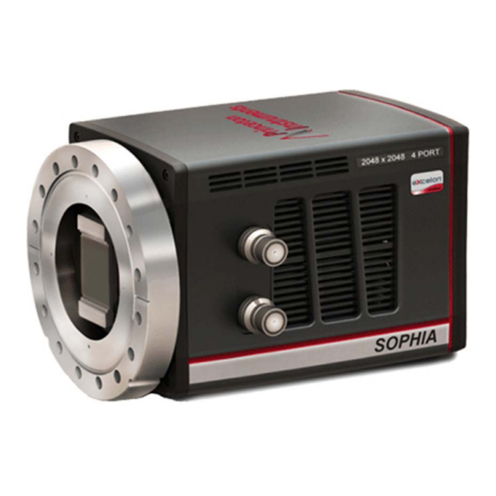
Page 16: Sophia-Xo Camera
2048 x 2048, 15 m pixel CCD camera that utilizes back-illuminated CCDs without AR coating for direct detection of the widest range of X-rays between ~ 10 eV and 30 keV. Designed utilizing Teledyne Princeton Instruments’ exclusive ArcTec™ thermoelectric cooling technology, SOPHIA-XO is the only camera that offers cooling down to -90°C with air-assist, liquid-assist, or air plus liquid assist for complete worry-free operation. -
Page 17: Figure 2-3: Sophia-Xo Power Supply Connectors And Indicators
Chapter 2 SOPHIA-XO Camera System Figure 2-3 shows the connectors and indicators found on the rear of the SOPHIA-XO power supply. REFERENCES: Refer to Section A.3, Power Specifications, on page 109 for complete voltage specifications. Figure 2-3: SOPHIA-XO Power Supply Connectors and Indicators OWER AULT OWER... -
Page 18: Ccd Array
Cooling Dark current is reduced in SOPHIA-XO camera systems by cooling the CCD array using Teledyne Princeton Instruments’ exclusive ArcTec™ technology using air and/or circulating coolant. To prevent condensation and contamination from occurring, cameras cooled this way are evacuated. Refer to Table A-3, Default Operating Temperature, on page 108 for specific cooling specifications. -
Page 19: External Coolant Circulator
(23ºC) water and ethylene glycol at 1 liter per minute. Refer to Section A.5, External Coolant Circulator Specifications, on page 110 for additional information. If desired, contact Teledyne Princeton Instruments for additional recommendations. Refer to Contact Information on page 136 for complete information. -
Page 20: Sophia-Xo Rear-Panel Connectors
® SOPHIA -XO System Manual Issue 3 2.1.4 SOPHIA-XO Rear-Panel Connectors Figure 2-4 illustrates the rear-panel connectors on a SOPHIA-XO camera. Figure 2-4: SOPHIA-XO Rear-Panel Connectors USB3 SHUTTER SYNC OUT1 OUT2 POWER Refer to Table 2-2 for information about each rear-panel connector. Table 2-2: SOPHIA-XO Rear-Panel Connectors (Sheet 1 of 2) Label Description... -
Page 21: Theory Of Operation
Chapter 2 SOPHIA-XO Camera System Table 2-2: SOPHIA-XO Rear-Panel Connectors (Sheet 2 of 2) Label Description OUT2 0 to +5.0 V programmable TTL-compatible logic level output capable of driving logic levels into 50 . This output can be programmed and inverted via the application software. -
Page 22: Cables
Certificate of Performance Each SOPHIA-XO camera is shipped with a Certificate of Performance which states that the camera system has been assembled and tested according to approved Teledyne Princeton Instruments procedures. It documents the camera’s performance data as measured during the testing of the SOPHIA-XO and lists the following camera- and customer-specific information: •... -
Page 23: Application Software
Chapter 2 SOPHIA-XO Camera System Application Software Teledyne Princeton Instruments offers a number of data acquisition software packages for use with SOPHIA-XO camera systems, including: ® • LightField The SOPHIA-XO camera can be operated using LightField, Teledyne Princeton ® Instruments’ 64-bit Windows compatible software package. -
Page 24: Accessories
SOPHIA-XO. For complete ordering information, contact Teledyne Princeton Instruments. 2.5.1 External Shutters Teledyne Princeton Instruments offers a variety of external shutters that are compatible with, and supported by, SOPHIA-XO cameras. Refer to Table 2-4 for the list of external shutters that are supported by SOPHIA-XO. -
Page 25: Unpack The System
When unpacking the system, examine the system components for any signs of shipping damage. If there are any, notify Teledyne Princeton Instruments immediately and file a claim with the carrier. Be sure to save the shipping carton for inspection by the carrier. -
Page 26: Sophia-Xo Camera And System Maintenance
2.7.3 Repairs Because the SOPHIA-XO camera system contains no user-serviceable parts, repairs must be performed by Teledyne Princeton Instruments. Should the system need repair, contact Teledyne Princeton Instruments customer support for instructions. Refer to Contact Information on page 136 for complete information. -
Page 27: Chapter 3: Install Lightfield
Chapter 3: Install LightField This chapter provides the installation procedure for LightField application software. NOTE: If LightField has already been successfully installed on the host computer, this chapter may be skipped. Prerequisites Before beginning to install LightField, verify that: ® •... - Page 28 ® SOPHIA -XO System Manual Issue 3 This page is intentionally blank.
-
Page 29: Chapter 4: System Block Diagrams
Chapter 4: System Block Diagrams This section provides block diagrams of typical system configurations. Figure 4-1: Block Diagram: Typical Air-Cooled Experiment 100/240 V OWER UPPLY USB C ABLE AMERA XPERIMENT ACUUM HAMBER Figure 4-2: Block Diagram: Typical Liquid-Cooled Experiment 100/240 V OWER UPPLY USB C... - Page 30 ® SOPHIA -XO System Manual Issue 3 This page is intentionally blank.
-
Page 31: Chapter 5: System Verification
Chapter 5: System Verification SOPHIA-XO cameras are designed without a protective window and are therefore shipped from the factory with a shipping plate installed. WARNING! The shipping plate must remain in place until camera operation has been verified as described in this chapter. Once camera operation has been verified, the SOPHIA-XO can be mounted to a vacuum chamber for normal operation. -
Page 32: Figure 5-1: Available Devices Area
® SOPHIA -XO System Manual Issue 3 5. Once LightField has launched, a SOPHIA-XO camera icon will be shown in the Devices area. See Figure 5-1. Figure 5-1: Available Devices Area 6. Drag the SOPHIA-XO icon into the Experiment Devices area. -
Page 33: Figure 5-2: Experiment Devices Area
Chapter 5 System Verification 7. The Experiment Settings stack on the left includes several expanders. Since this is a new experiment, the default configuration settings for the camera are preconfigured. See Figure 5-2. Figure 5-2: Experiment Devices Area The Status bar across the bottom of the window includes an icon for temperature status. -
Page 34: Data Acquisition
® SOPHIA -XO System Manual Issue 3 5.1.1 Data Acquisition Perform the following procedure to acquire live data: Click on the View tab located above Available Devices to change focus to the View area. See Figure 5-3. Figure 5-3: View Area... -
Page 35: Figure 5-4: View Area Displaying An Image
Chapter 5 System Verification 2. Click Run to initiate Preview mode. In this mode, images are continuously acquired and displayed. See Figure 5-4. Figure 5-4: View Area Displaying an Image... -
Page 36: System Shutdown
® SOPHIA -XO System Manual Issue 3 3. Adjust the lens aperture, intensity scaling, and focus for the best image as viewed on the computer monitor. Imaging tips include: • Begin with the lens blocked off and then set the lens at the smallest possible aperture (i.e., the largest f-stop.) •... -
Page 37: Chapter 6: Hardware Configuration
Chapter 6: Hardware Configuration This chapter provides information about mounting a SOPHIA-XO camera to a vacuum chamber, as well as instructions for installing optional accessories. Mount SOPHIA-XO to a Vacuum Chamber SOPHIA-XO cameras are designed without a protective window and are therefore shipped from the factory with a shipping plate installed. -
Page 38: Figure 6-1: Typical Sophia-Xo Shipping Plate
11. Use a ½” torque wrench to tighten all bolts to a torque of 180 in-lbs ± 10 in-lbs. 12. Evacuate the chamber before applying power to the SOPHIA-XO camera. 13. Teledyne Princeton Instruments recommends a helium leak check upon initial vacuum pump down before operating the camera. -
Page 39: External Shutter Installation
External Shutter Installation CAUTION! In order to prevent potential permanent damage to either the SOPHIA-XO camera and/or the shutter, always contact Teledyne Princeton Instruments before connecting an external shutter that is not listed in Table 2-4, Supported External Shutters, on page 24 to a SOPHIA-XO. Refer to Contact Information on page 136 for complete information. -
Page 40: Experiment Shutdown
® SOPHIA -XO System Manual Issue 3 6. Plug the external circulator into a 100-240 V , 47-63 Hz power source. 7. Turn the coolant circulator on. CAUTION! When configuring an external coolant circulator, adhere to the following: • Coolant flow-rate should never exceed 0.8 gal/minute. -
Page 41: Exposure
Chapter 7: Exposure This chapter discusses factors that may affect the signal acquired on the CCD array, such as: • Exposure Time; • CCD Temperature; • Dark Charge; • Saturation. Exposure Time Exposure time is the time between commands sent by the data acquisition software to start and stop signal accumulation on the sensor. -
Page 42: Ccd Temperature
® SOPHIA -XO System Manual Issue 3 Note that the READOUT signal is: • LOW during Shutter Open/Close Compensation Times; • LOW during Exposure Time; • HIGH during Readout. Since the shutter behaves like an iris, the opening and closing of the shutter will cause the center of the CCD to be exposed slightly longer than the edges. -
Page 43: Dark Charge
CCD temperature possible. CAUTION! If a sudden change in the baseline signal is observed, there may be excessive humidity in the camera vacuum enclosure. Turn off the camera and contact Teledyne Princeton Instruments Customer Support. Refer to Contact Information on page 136 for complete contact information. -
Page 44: Table 7-1: Readout Noise Penalty Vs Number Of Acquired Frames
® SOPHIA -XO System Manual Issue 3 For example, when acquiring one frame of dark data to generate the subtractable pattern, the dark pattern readout noise will be ~1.414N , which is an increase of ~41% over the baseline readout noise. This value is calculated as follows: -------- - -------- - -------- -... -
Page 45: Clean Until Trigger
Chapter 7 Exposure 7.3.1 Clean Until Trigger When using an external trigger to initiate data readout, SOPHIA-XO supports Clean Until Trigger (CUT,) an additional level of cleaning/removing accumulated dark charge that continues until the moment the incoming trigger pulse is received. REFERENCES: For information about the use and configuration of external triggers, refer to:... -
Page 46: Normal Shutter Mode
® SOPHIA -XO System Manual Issue 3 7.3.1.1 Normal Shutter Mode When an incoming Trigger pulse has been received, cleaning of the array stops as soon as the current cleaning pattern has been completed and shifted. Because the incoming trigger is not synchronous with the cleaning cycle, there is an inherent jitter of up to one cleaning cycle in the system’s response to an incoming trigger. -
Page 47: Open Before Trigger Mode
Chapter 7 Exposure 7.3.1.2 Open Before Trigger Mode With Open Before Trigger shutter mode, the shutter is opened at the beginning of Clean Until Trigger. As with Normal mode, once the incoming Trigger pulse has been received, cleaning of the array stops as soon as the current cleaning pattern has been completed and shifted. -
Page 48: Saturation
® SOPHIA -XO System Manual Issue 3 Saturation When signal levels in some part of the image are very high, charge generated in one pixel may exceed the well capacity of the pixel, spilling over into adjacent pixels in a process called blooming. -
Page 49: Chapter 8: Analog To Digital Conversion
Chapter 8: Analog to Digital Conversion After the programmed exposure time has elapsed, accumulated charge stored in the CCD array must be: • Read out; • Converted to a digital format; • Transferred to the application software where it can be displayed and/or stored. The number of ports used to read out data and other Analog-to Digital conversion factors are configured within LightField on the Analog to Digital Conversion expander using the following parameters:... -
Page 50: Readout Ports Used
® SOPHIA -XO System Manual Issue 3 Readout Ports Used Readout begins by moving charge from the CCD image area to the shift register(s) in which each pixel typically has twice the capacity of each image pixel. SOPHIA-XO is equipped with four output amplifiers/ports which provides flexibility in how acquired charge is read out. -
Page 51: Figure 8-3: Data Readout Using Two Output Ports
Chapter 8 Analog to Digital Conversion • 2 amplifiers/output ports; Figure 8-3 illustrates the charge being shifted and read out using two SOPHIA-XO output ports. Figure 8-3: Data Readout Using Two Output Ports Shift Register Shift Register Output 1 Output 2 Output Output Amplifier... -
Page 52: Output Amplifier
® SOPHIA -XO System Manual Issue 3 8.1.1 Output Amplifier Each Output Amplifier that has been configured for use amplifies the collected charge from the output node and transfers it to the ADC. The amount of Gain that is applied by each Output Amplifier is user configurable. -
Page 53: Adc Offset (Bias)
A/D) to a value in the range of 500-600 counts lower. WARNING! If a sudden change in the baseline signal is observed, there may be excessive humidity in the camera vacuum enclosure. Turn off the camera and contact Teledyne Princeton Instruments Customer Support. Refer to Contact Information on page 136 for complete information. -
Page 54: Analog Gain
® SOPHIA -XO System Manual Issue 3 Analog Gain Controller gain, a configurable function of the preamplifier, changes the relationship between the number of electrons acquired on the CCD and the Analog-to-Digital Units (ADUs) generated. The level of gain is configured by the Analog Gain parameter on the Analog to Digital Conversion expander. -
Page 55: Example
Chapter 8 Analog to Digital Conversion 8.3.1 Example In this example, it is assumed the incoming light level is identical in all three instances. The electron counts listed in Table 8-1 are used to illustrate the relative effects of changing controller gain settings and may not reflect actual performance. Achievable gain depends on the CCD being used as well as the readout rate that has been configured. - Page 56 ® SOPHIA -XO System Manual Issue 3 This page is intentionally blank.
-
Page 57: Full Frame Readout
Chapter 9: Full Frame Readout When operating in Full Frame mode, SOPHIA-XO reads and processes a complete frame of data at a time via 1, 2, or 4 output ports. Every pixel of information is digitized individually. REFERENCES: Refer to Section 8.1, Readout Ports Used, on page 50 for complete information about selecting the number of ports... -
Page 58: Figure 9-2: Full Frame Readout: One Row Of Charge Shifted Into
® SOPHIA -XO System Manual Issue 3 Figure 9-2: Full Frame Readout: One Row of Charge Shifted into Shift Register Shift Register Amplifier Output Node Image Area NOTE: Typically, each pixel within the Shift Register can store up to twice as much charge as pixels within the CCD imaging area. -
Page 59: Calculating Image Acquisition/Readout Time
Chapter 9 Full Frame Readout Calculating Image Acquisition/Readout Time The total time required to acquire and readout a full frame of data at full resolution is calculated as follows: where: • is the CCD readout time; Refer to Section 9.1.1, CCD Readout Time, for additional information. -
Page 60: Experiment Timing
® SOPHIA -XO System Manual Issue 3 • is the time needed to shift one line into the shift register. • is the time needed to process one pixel. NOTE: Equation 2 above does not include certain overhead times. A more accurate calculation of CCD Readout Time is provided by LightField. -
Page 61: Trigger Response
Chapter 9 Full Frame Readout 9.2.1 Trigger Response The Trigger Response parameter defines how, upon receipt of an incoming trigger pulse, SOPHIA-XO reads out data that have been acquired. Supported Trigger Response modes are: • Response; • Start on Single Trigger;... -
Page 62: Figure 9-5: Full Frame Timing Diagram: No Response, Normal
® SOPHIA -XO System Manual Issue 3 9.2.1.1.1 Normal Figure 9-5 illustrates the timing diagram for No Response mode combined with Normal shutter mode. Figure 9-5: Full Frame Timing Diagram: No Response, Normal Pgm’d ACQUIRE Cleans SHUTTER Normal EXPOSE READOUT 9.2.1.1.2 Always Closed Figure 9-6... -
Page 63: Figure 9-7: Full Frame Timing Diagram: No Response, Always Open
Chapter 9 Full Frame Readout 9.2.1.1.3 Always Open Figure 9-7 illustrates the timing diagram for No Response mode combined with Always Open shutter mode. Figure 9-7: Full Frame Timing Diagram: No Response, Always Open Pgm’d ACQUIRE Cleans SHUTTER Always Open EXPOSE READOUT This mode is typically used when an experiment does not support waiting for the... -
Page 64: Start On Single Trigger
® SOPHIA -XO System Manual Issue 3 9.2.1.2 Start on Single Trigger Begins the experiment when the trigger is received and the system executes all programmed events. Supported Shutter modes are: • Normal; • Always Closed; • Always Open; • Open Before Trigger. -
Page 65: Figure 9-9: Full Frame Timing Diagram: Start On Single Trigger
Chapter 9 Full Frame Readout 9.2.1.2.2 Always Closed Figure 9-9 illustrates the timing diagram for Start on Single Trigger mode combined with Always Closed shutter mode. Figure 9-9: Full Frame Timing Diagram: Start on Single Trigger, Always Closed Pgm’d Clean Until ACQUIRE Cleans Trigger**... -
Page 66: Figure 9-11: Full Frame Timing Diagram: Start On Single Trigger
® SOPHIA -XO System Manual Issue 3 9.2.1.2.4 Open Before Trigger Figure 9-11 illustrates the timing diagram for Start On Single Trigger mode combined with Open Before Trigger shutter mode. Figure 9-11: Full Frame Timing Diagram: Start on Single Trigger, Open Before Trigger Clean Until Pgm’d ACQUIRE... -
Page 67: Readout Per Trigger
Chapter 9 Full Frame Readout 9.2.1.3 Readout Per Trigger With Readout Per Trigger, all exposures are synchronized with an incoming trigger pulse. Synchronization occurs on either the Rising Edge or Falling Edge of the trigger pulse which is configured using the Trigger Determined By parameter on the Trigger In expander. -
Page 68: Figure 9-13: Full Frame Timing Diagram: Readout Per Trigger, Always Closed
® SOPHIA -XO System Manual Issue 3 Because a shutter requires a finite length of time to fully open, the trigger pulse from the experiment must precede the start of data acquisition by at least this length of time. If it does not, the shutter may not be completely open throughout the duration of the desired data acquisition, and data acquisition may even be missed completely. -
Page 69: Figure 9-14: Full Frame Timing Diagram: Readout Per Trigger, Always Open
Chapter 9 Full Frame Readout 9.2.1.3.3 Always Open Figure 9-14 illustrates the timing diagram for Readout Per Trigger mode combined with Always Open shutter mode. Figure 9-14: Full Frame Timing Diagram: Readout Per Trigger, Always Open Clean Clean Until Until Pgm’d ACQUIRE Trigger**... -
Page 70: Figure 9-15: Full Frame Timing Diagram: Readout Per Trigger
® SOPHIA -XO System Manual Issue 3 9.2.1.3.4 Open Before Trigger Figure 9-15 illustrates the timing diagram for Readout Per Trigger mode combined with Open Before Trigger shutter mode. Figure 9-15: Full Frame Timing Diagram: Readout Per Trigger, Open Before Trigger Clean Clean Until Pgm’d... -
Page 71: Expose During Trigger Pulse
Chapter 9 Full Frame Readout 9.2.1.4 Expose During Trigger Pulse Controls when exposure begins and ends. Supported Shutter modes are: • Normal; • Always Closed; • Always Open; • Open Before Trigger. The effect each of these shutter modes has on experiment synchronization is described in the following sections. -
Page 72: Figure 9-17: Timing Diagram: Expose During Trigger, Always Closed
® SOPHIA -XO System Manual Issue 3 9.2.1.4.2 Always Closed Figure 9-17 illustrates the timing diagram for Expose During Trigger Pulse mode combined with Always Closed shutter mode. Figure 9-17: Timing Diagram: Expose During Trigger, Always Closed Clean Pgm’d Until ACQUIRE Cleans Trigger**... -
Page 73: Figure 9-19: Timing Diagram: Expose During Trigger, Open Before Trigger
Chapter 9 Full Frame Readout 9.2.1.4.4 Open Before Trigger Figure 9-19 illustrates the timing diagram for Expose During Trigger Pulse mode combined with Open Before Trigger shutter mode. Figure 9-19: Timing Diagram: Expose During Trigger, Open Before Trigger Pgm’d Clean Until ACQUIRE Cleans Trigger**... -
Page 74: Trigger Determined By
® SOPHIA -XO System Manual Issue 3 9.2.2 Trigger Determined By When using an external trigger to initiate a readout, SOPHIA-XO can be configured to respond to: • The rising edge of the incoming trigger pulse; • The falling edge of the incoming trigger pulse. The Trigger Determined By parameter configures this behavior. -
Page 75: Trigger Out
Chapter 9 Full Frame Readout Trigger Out In addition to being able to synchronize SOPHIA-XO with an experiment, additional equipment can be synchronized using the Trigger Out connector on the rear of SOPHIA-XO. Two trigger out pulses are configured on the Trigger Out expander, shown in Figure 9-20. - Page 76 ® SOPHIA -XO System Manual Issue 3 This page is intentionally blank.
-
Page 77: Chapter 10: Kinetics Readout
Chapter 10: Kinetics Readout Kinetics mode uses the CCD to expose and store a limited number of images in rapid succession. The time it takes to shift each line (or row) on a CCD is typically within the range of a few hundred nanoseconds to few microseconds, depending on the CCD. For SOPHIA-XO, this shift can be achieved in as little as 24 s. -
Page 78: 10.1 Kinetics Mode Parameters
® SOPHIA -XO System Manual Issue 3 10.1 Kinetics Mode Parameters Kinetics mode is selected and configured on the Readout expander as shown in Figure 10-2. Figure 10-2: Typical Readout Expander: Kinetics Mode Parameters 10.1.1 Kinetics Window Height Defines the height, in rows, of the unmasked area of the CCD to be used for kinetics. Valid values are [1 …... -
Page 79: 10.2 Experiment Timing
Shutters are not covered by the warranty. If an application requires both NORMAL shutter mode and Kinetics Readout, contact Teledyne Princeton Instruments for assistance prior to attempting this configuration. Refer Contact Information on page 136 for complete information. -
Page 80: Trigger Response
® SOPHIA -XO System Manual Issue 3 10.2.1 Trigger Response The Trigger Response parameter defines how SOPHIA-XO responds upon receipt of an incoming trigger pulse. Supported Trigger Response modes are: • Response; • Start on Single Trigger; • Readout Per Trigger;... -
Page 81: Figure 10-4: Kinetics Timing Diagram: No Response, Always Closed
Kinetics Readout 10.2.1.1.1 Normal CAUTION! The use of this mode is strongly discouraged. Contact Teledyne Princeton Instruments for assistance before implementing this mode. Refer to Contact Information page 136 for complete information. 10.2.1.1.2 Always Closed Figure 10-4 illustrates the timing diagram for No Response mode combined with Always Closed shutter mode. -
Page 82: Start On Single Trigger
2. In all timing diagrams, Trigger Determined By Rising Edge is illustrated. 10.2.1.2.1 Normal CAUTION! The use of this mode is strongly discouraged. Contact Teledyne Princeton Instruments for assistance before implementing this mode. Refer to Contact Information page 136 for complete information. -
Page 83: Figure 10-6: Kinetics Timing Diagram: Start On Single Trigger, Always Closed
Chapter 10 Kinetics Readout 10.2.1.2.2 Always Closed Figure 10-4 illustrates the timing diagram for Start on Single Trigger mode combined with Always Closed shutter mode. Figure 10-6: Kinetics Timing Diagram: Start on Single Trigger, Always Closed Pgm’d Clean Until ACQUIRE Cleans Trigger** TRIGGER... -
Page 84: Figure 10-8: Kinetics Timing Diagram: Start On Single Trigger
® SOPHIA -XO System Manual Issue 3 10.2.1.2.4 Open Before Trigger Figure 10-8 illustrates the timing diagram for Start On Single Trigger mode combined with Open Before Trigger shutter mode. Figure 10-8: Kinetics Timing Diagram: Start On Single Trigger, Open Before Trigger Pgm’d Clean Until ACQUIRE... -
Page 85: Readout Per Trigger
2. In all timing diagrams, Trigger Determined By Rising Edge is illustrated. 10.2.1.3.1 Normal CAUTION! The use of this mode is strongly discouraged. Contact Teledyne Princeton Instruments for assistance before using this shutter mode. Refer to Contact Information page 136 for complete information. -
Page 86: Figure 10-9: Kinetics Timing Diagram: Readout Per Trigger, Always Closed
® SOPHIA -XO System Manual Issue 3 10.2.1.3.2 Always Closed Figure 10-15 illustrates the timing diagram for Readout Per Trigger mode combined with Always Closed shutter mode. Figure 10-9: Kinetics Timing Diagram: Readout Per Trigger, Always Closed Clean Pgm’d Until ACQUIRE Cleans Trigger**... -
Page 87: Figure 10-11: Kinetics Timing Diagram: Readout Per Trigger, Open
Chapter 10 Kinetics Readout 10.2.1.3.4 Open Before Trigger Figure 10-17 illustrates the timing diagram for Readout Per Trigger mode combined with Open Before Trigger shutter mode. Figure 10-11:Kinetics Timing Diagram: Readout Per Trigger, Open Before Trigger Clean Clean Until Until Pgm’d ACQUIRE Trigger**... -
Page 88: Shift Per Trigger
2. In all timing diagrams, Trigger Determined By Rising Edge is illustrated. 10.2.1.4.1 Normal CAUTION! The use of this mode is strongly discouraged. Contact Teledyne Princeton Instruments for assistance before using this shutter mode. Refer to Contact Information page 136 for complete information. -
Page 89: Figure 10-12:Kinetics Timing Diagram: Shift Per Trigger, Always Closed
Chapter 10 Kinetics Readout 10.2.1.4.2 Always Closed Figure 10-15 illustrates the timing diagram for Shift Per Trigger mode combined with Always Closed shutter mode. Figure 10-12:Kinetics Timing Diagram: Shift Per Trigger, Always Closed Clean Until Pgm’d Clean Until ACQUIRE Trigger** Cleans Trigger** TRIGGER... -
Page 90: Figure 10-14:Kinetics Timing Diagram: Shift Per Trigger, Open Before Trigger
® SOPHIA -XO System Manual Issue 3 10.2.1.4.4 Open Before Trigger Figure 10-17 illustrates the timing diagram for Shift Per Trigger mode combined with Open Before Trigger shutter mode. Figure 10-14:Kinetics Timing Diagram: Shift Per Trigger, Open Before Trigger Clean Until Pgm’d Clean Until... -
Page 91: Expose During Trigger Pulse
2. In all timing diagrams, Trigger Determined By Rising Edge is illustrated. 10.2.1.5.1 Normal CAUTION! The use of this mode is strongly discouraged. Contact Teledyne Princeton Instruments for assistance before using this shutter mode. Refer to Contact Information page 136 for complete information. -
Page 92: Figure 10-15:Kinetics Timing Diagram: Expose During Trigger, Always Closed
® SOPHIA -XO System Manual Issue 3 10.2.1.5.2 Always Closed Figure 10-15 illustrates the timing diagram for Expose During Trigger Pulse mode combined with Always Closed shutter mode. Figure 10-15:Kinetics Timing Diagram: Expose During Trigger, Always Closed Clean Pgm’d Until ACQUIRE Cleans Trigger**... -
Page 93: Figure 10-17: Kinetics Timing Diagram: Expose During Trigger Pulse
Chapter 10 Kinetics Readout 10.2.1.5.4 Open Before Trigger Figure 10-17 illustrates the timing diagram for Expose During Trigger Pulse mode combined with Open Before Trigger shutter mode. Figure 10-17:Kinetics Timing Diagram: Expose During Trigger Pulse, Open Before Trigger Pgm’d Clean Until ACQUIRE Cleans Trigger**... -
Page 94: Trigger Determined By
® SOPHIA -XO System Manual Issue 3 10.2.2 Trigger Determined By When using an external trigger to initiate a readout, SOPHIA-XO can be configured to respond to: • The rising edge of the incoming trigger pulse; • The falling edge of the incoming trigger pulse. The Trigger Determined By parameter configures this behavior. -
Page 95: 10.3 Trigger Out
Chapter 10 Kinetics Readout 10.3 Trigger Out In addition to being able to synchronize SOPHIA-XO with an experiment, additional equipment can be synchronized using the Trigger Out connector on the rear of SOPHIA-XO. Two trigger out pulses are configured on the Trigger Out expander, shown in Figure 10-18. - Page 96 ® SOPHIA -XO System Manual Issue 3 This page is intentionally blank.
-
Page 97: Chapter 11: Binning
Chapter 11: Binning Binning is the process of summing data from adjacent pixels to form a single pixel, often called a Super Pixel. Binning can be accomplished in one of two ways: • Hardware; • Software. Rectangular groups of pixels of any size may be binned together subject to some hardware and software limitations. - Page 98 ® SOPHIA -XO System Manual Issue 3 Figure 11-1: 2 × 2 Binning B1 C1 D1 B2 C2 D2...
-
Page 99: 11.2 Software Binning
Chapter 11 Binning 11.2 Software Binning One limitation of hardware binning is that the shift register pixels and the output node are typically only 2-3 times the size of imaging pixels. Consequently, if the total charge binned together exceeds the capacity of the shift register or output node, the data will be corrupted. -
Page 100: Figure 11-2: Binning And Array Orientation
® SOPHIA -XO System Manual Issue 3 Figure 11-2: Binning and Array Orientation UTPUT ERIAL EGISTER to A4 to A4 to B4 to C4 to D4 to D1 (0,0) (0,0) INNING LONG OLUMNS INNING LONG INNING CCURS IN ERIAL EGISTER INNING CCURS IN UTPUT... -
Page 101: Chapter 12: Shutter Configuration And Control
Chapter 12: Shutter Configuration and Control This chapter provides information about the configuration and control of an external shutter that has been connected to SOPHIA-XO’s. 12.1 Configuration Shutter information is configured within LightField on the Shutter expander. Figure 12-1 illustrates a typical Shutter expander when there is no external shutter installed. Figure 12-1: Typical Shutter Expander: No External Shutter Installed Figure 12-2 illustrates a typical Shutter expander when an external shutter has been... -
Page 102: Mode
Shutters are not covered by the warranty. If an application requires both NORMAL shutter mode and Kinetics Readout, contact Teledyne Princeton Instruments for assistance prior to attempting this configuration. Refer Contact Information on page 136 for complete information. -
Page 103: Internal Shutter
The shutter drive can apply voltage up to to an external shutter. Therefore, when using a shutter not supplied by Teledyne Princeton Instruments, it is the responsibility of each user to assure all connections, other than ground, to the external shutter are insulated to prevent accidental contact by personnel. -
Page 104: Figure 12-3: Typical Shutter Configuration Add-In: Default External Shutter
® SOPHIA -XO System Manual Issue 3 LightField automatically detects when an external shutter has been connected to SOPHIA-XO. By default, the external shutter configured for use is a Prontor Magnetic 0 (23 mm). When using a different supported shutter (refer to Table 2-4, Supported External Shutters, on page 24 for a list of supported shutters,) before beginning to configure parameters or acquiring data, the correct device must be selected via the Shutter... -
Page 105: Figure 12-5: Typical Update Shutter Type Action
Chapter 12 Shutter Configuration and Control Once the new shutter has been selected, the Update and Restore Experiment to Default action is then enabled. See Figure 12-5. Figure 12-5: Typical Update Shutter Type Action Click on Update and Restore Experiment to Default to update the external shutter information within the SOPHIA-XO system. - Page 106 ® SOPHIA -XO System Manual Issue 3 This page is intentionally blank.
-
Page 107: Appendix A: Technical Specifications
All specifications are subject to change. This appendix provides some technical information and specifications for SOPHIA-XO cameras and optional accessories. Additional information may be found on data sheets available on the Teledyne Princeton Instruments website (www.princetoninstruments.com). System Dimensions and Weight... -
Page 108: Thermal Characteristics
® SOPHIA -XO System Manual Issue 3 Table A-2: CCD Array Specifications (Sheet 2 of 2) Specification SOPHIA-XO 2048 eXcelon SOPHIA-XO 2048-13.5m Read Noise Low Noise High Capacity 100 kHz – – – 4.5 e 3.5 e 11 e 1 MHz –... -
Page 109: Power Specifications
AC plug from the wall receptacle. CAUTION! Use of a power supply other than that provided with the SOPHIA-XO camera will void the camera warranty. For specific power supply requirements, contact Teledyne Princeton Instruments. Refer to Contact Information page 136 for complete information. -
Page 110: Ventilation
® SOPHIA -XO System Manual Issue 3 A.4.1 Ventilation A minimum of 1 inch (2.54 cm) clearance is required around all vents on the SOPHIA-XO camera. Where SOPHIA-XO is within an enclosure, >30 cfm air circulation and heat dissipation of 250 W is required. External Coolant Circulator Specifications CAUTION! Never set the coolant temperature below the dew point. -
Page 111: Shutter Connector
Figure 2-4 on page 20). Shutters that have been supplied by Teledyne Princeton Instruments will be equipped with the proper connector. However, when using a non-Teledyne Princeton Instruments’ supplied shutter, refer to Table A-8 for information about the required shutter connector. -
Page 112: Minimum Host Computer Specifications
® SOPHIA -XO System Manual Issue 3 Minimum Host Computer Specifications NOTE: Computers and operating systems experience frequent updates. Therefore, the following sections are intended to provide minimum system requirements for operating a SOPHIA-XO camera. A faster computer with 5 GB or larger memory (RAM) will greatly enhance the software performance during live mode operations. -
Page 113: Appendix B: Outline Drawings
Appendix B: Outline Drawings This appendix provides outlines drawing for the SOPHIA-XO Camera System. Figure B-1: Outline Drawing: SOPHIA-XO Camera... -
Page 114: Figure B-2: Outline Drawing: Sophia-Xo Power Supply
® SOPHIA -XO System Manual Issue 3 Figure B-2: Outline Drawing: SOPHIA-XO Power Supply... -
Page 115: Appendix C: Custom Modes
In addition to Binning and Regions of Interest, Custom Sensor can be used to reduce Readout Time by reducing the apparent size of the CCD array. CAUTION! Teledyne Princeton Instruments does not encourage users to change these settings. For most applications, default values provide the best results. It is strongly advised that users contact the factory for assistance before customizing the chip definition. -
Page 116: Custom Timing
® SOPHIA -XO System Manual Issue 3 By changing the values in the Active fields, image acquisition speed can be increased by reducing the size of the active area in the definition. The result will be faster, but lower resolution, data acquisition. Operating in this mode would ordinarily require that the chip be masked so that only the reduced active area is exposed. -
Page 117: Appendix D: Drain Coolant From Sophia-Xo
Appendix D: Drain Coolant from SOPHIA-XO This appendix provides information necessary to safely drain coolant from within the SOPHIA-XO camera body. Place SOPHIA-XO camera body on a flat, secure surface with the two coolant fittings facing down and positioned over a container that will collect the coolant as it is draining. -
Page 118: Figure D-2: Depressing Coolant Fittings' Center Pistons
® SOPHIA -XO System Manual Issue 3 2. Using two small screwdrivers, Allen wrenches, or similar tools, carefully depress the center piston on each coolant fitting simultaneously. See Figure D-2 Figure D-2: Depressing Coolant Fittings’ Center Pistons AREFULLY EPRESS SING MALL CREWDRIVERS LLEN... - Page 119 Appendix D Drain Coolant from SOPHIA-XO 3. When the coolant has drained, release the pistons and verify that they return to their normal, closed position. 4. Use a soft cloth to wipe off any stray coolant from the SOPHIA-XO and/or surrounding areas.
- Page 120 ® SOPHIA -XO System Manual Issue 3 This page is intentionally blank.
-
Page 121: Appendix E: Backfilling For Storage Or Shipment
Appendix E: Backfilling for Storage or Shipment To protect the camera while in storage or during shipment, you need to re-mount the shipping plate to the front of the camera: this plate was mounted to the camera before it was shipped to you from the factory. In addition, you will need to backfill the camera with dry Nitrogen. -
Page 122: Figure E-2: Shipping Plate Valve And Fill Port Adapter
® SOPHIA -XO System Manual Issue 3 3. Using a flat-blade screwdriver, close the valve (i.e., screw it in completely.) See Figure E-2. Figure E-2: Shipping Plate Valve and Fill Port Adapter DAPTER ALVE 4. If it is not already attached to the shipping plate, screw in the fill port adapter (with O-ring). -
Page 123: Appendix F: Troubleshooting
Appendix F: Troubleshooting WARNING! Do not attach or remove any cables while the camera system is powered on. The SOPHIA-XO power supply is equipped with a red FAULT LED on its rear panel. When the system is operating normally, this LED is extinguished. However, when an error has been detected, the number of times the LED flashes is indicative of the specific fault. -
Page 124: General Camera Faults/Errors
A change in the baseline signal is normal if the temperature, gain, or speed setting has been changed. If this occurs when none of these settings have been changed, there may be excessive humidity in the camera vacuum enclosure. Turn off the camera and contact Teledyne Princeton Instruments Customer Support. Refer to Contact Information... -
Page 125: Camera Stops Working
Appendix F Troubleshooting F.1.4 Camera Stops Working Problems with the host computer system or software may have side effects that appear to be hardware problems. If you are sure the problem is in the camera system hardware, perform these preliminary system checks: •... -
Page 126: Camera Loses Temperature Lock
® SOPHIA -XO System Manual Issue 3 • The circulator is higher than the camera. Reposition the circulator so that it is 6” [150 mm] or more below the camera. The vertical distance should not exceed 10 feet [3 m]. Typically, the camera is at table height and the circulator is on the floor. -
Page 127: External Coolant Circulator: Low Coolant (Air In The Hoses)
Appendix F Troubleshooting F.2.4 External Coolant Circulator: Low Coolant (Air in the Hoses) WARNING! If more than 2” [50.8 mm] of a coolant line is filled with air, the pump will stop working and may be damaged. If flow stops while the pump is on, turn off the external coolant circulator and add coolant. -
Page 128: Shutter Faults/Errors
® SOPHIA -XO System Manual Issue 3 Shutter Faults/Errors SOPHIA-XO’s shutter has a Minimum Exposure Time (MET) of 25 ms. Operating the shutter in Normal mode with exposure times significantly shorter than the MET will not only result in incomplete CCD exposure (i.e., the shutter may not have time to open completely before starting to close,) but will also lead to premature shutter wear and eventually complete shutter failure. -
Page 129: Lightfield Faults/Errors
Appendix F Troubleshooting LightField Faults/Errors This section provides information about troubleshooting problems that may occur with LightField. F.4.1 Devices Missing When LightField is started, it looks for devices that are powered on and connected via a communications interface to the host computer. If it cannot find a device that was used in the last experiment, the dialog shown in Figure F-1 is displayed while LightField... -
Page 130: Device Is Occupied
® SOPHIA -XO System Manual Issue 3 F.4.2 Device is Occupied Although multiple instances of LightField can be running at the same time, any device that is currently in use by one instance of LightField will be shown within the Available Devices area of all other instances as Occupied. - Page 131 Appendix F Troubleshooting When a filename is listed, it indicates that the data being displayed are static (i.e., data from the indicated file,) and not live data that are currently being acquired. To return to a live data view, click on the to the right of the filename to view the pull-down menu and select .
- Page 132 ® SOPHIA -XO System Manual Issue 3 This page is intentionally blank.
-
Page 133: Warranty And Service
(1) year after shipment. During this period, Teledyne Princeton Instruments will repair the product or, at its sole option, repair or replace any defective part without charge to you. You must deliver the entire product to the Teledyne Princeton Instruments factory or, at our option, to a factory-authorized service center. -
Page 134: Sealed Chamber Integrity Limited 12 Month Warranty
(1) year from shipment. Teledyne Princeton Instruments does not warrant that the function of the software will meet your requirements or that operation will be uninterrupted or error free. -
Page 135: Owner's Manual And Troubleshooting
3. All warranty service must be made by the Teledyne Princeton Instruments factory or, at our option, an authorized service center. 4. Before products or parts can be returned for service you must contact the Teledyne Princeton Instruments factory and receive a return authorization number (RMA.) Products or parts returned for service without a return authorization evidenced by an RMA will be sent back freight collect. -
Page 136: Contact Information
In no event shall Teledyne Princeton Instruments’ liability exceed the cost of the repair or replacement of the defective product or part. - Page 137 This page is intentionally blank.
- Page 138 info@princetoninstruments.com USA +1 877-474-2286 | France +33 (1) 60 86 03 65 | Germany +49 (0) 89 660 7793 | UK & Ireland +44 (0) 1628 472 346 Singapore +65 6408 6240 | China +86 10 659 16460 | Japan +81 (3) 5639 2741...
Need help?
Do you have a question about the Princeton Instruments Sophia-XO and is the answer not in the manual?
Questions and answers